US11558079B2 - Radio frequency communication systems with interference cancellation for coexistence - Google Patents
Radio frequency communication systems with interference cancellation for coexistence Download PDFInfo
- Publication number
- US11558079B2 US11558079B2 US16/738,834 US202016738834A US11558079B2 US 11558079 B2 US11558079 B2 US 11558079B2 US 202016738834 A US202016738834 A US 202016738834A US 11558079 B2 US11558079 B2 US 11558079B2
- Authority
- US
- United States
- Prior art keywords
- interference cancellation
- signal
- interference
- transmit
- circuit
- Prior art date
- Legal status (The legal status is an assumption and is not a legal conclusion. Google has not performed a legal analysis and makes no representation as to the accuracy of the status listed.)
- Active
Links
Images


Classifications
-
- H—ELECTRICITY
- H04—ELECTRIC COMMUNICATION TECHNIQUE
- H04B—TRANSMISSION
- H04B1/00—Details of transmission systems, not covered by a single one of groups H04B3/00 - H04B13/00; Details of transmission systems not characterised by the medium used for transmission
- H04B1/38—Transceivers, i.e. devices in which transmitter and receiver form a structural unit and in which at least one part is used for functions of transmitting and receiving
- H04B1/40—Circuits
- H04B1/50—Circuits using different frequencies for the two directions of communication
- H04B1/52—Hybrid arrangements, i.e. arrangements for transition from single-path two-direction transmission to single-direction transmission on each of two paths or vice versa
- H04B1/525—Hybrid arrangements, i.e. arrangements for transition from single-path two-direction transmission to single-direction transmission on each of two paths or vice versa with means for reducing leakage of transmitter signal into the receiver
-
- H—ELECTRICITY
- H04—ELECTRIC COMMUNICATION TECHNIQUE
- H04B—TRANSMISSION
- H04B1/00—Details of transmission systems, not covered by a single one of groups H04B3/00 - H04B13/00; Details of transmission systems not characterised by the medium used for transmission
- H04B1/02—Transmitters
- H04B1/04—Circuits
- H04B1/0475—Circuits with means for limiting noise, interference or distortion
-
- H—ELECTRICITY
- H04—ELECTRIC COMMUNICATION TECHNIQUE
- H04B—TRANSMISSION
- H04B1/00—Details of transmission systems, not covered by a single one of groups H04B3/00 - H04B13/00; Details of transmission systems not characterised by the medium used for transmission
- H04B1/06—Receivers
- H04B1/10—Means associated with receiver for limiting or suppressing noise or interference
- H04B1/12—Neutralising, balancing, or compensation arrangements
- H04B1/123—Neutralising, balancing, or compensation arrangements using adaptive balancing or compensation means
-
- H—ELECTRICITY
- H04—ELECTRIC COMMUNICATION TECHNIQUE
- H04B—TRANSMISSION
- H04B7/00—Radio transmission systems, i.e. using radiation field
- H04B7/14—Relay systems
- H04B7/15—Active relay systems
- H04B7/155—Ground-based stations
- H04B7/15564—Relay station antennae loop interference reduction
- H04B7/15585—Relay station antennae loop interference reduction by interference cancellation
-
- H—ELECTRICITY
- H04—ELECTRIC COMMUNICATION TECHNIQUE
- H04L—TRANSMISSION OF DIGITAL INFORMATION, e.g. TELEGRAPHIC COMMUNICATION
- H04L5/00—Arrangements affording multiple use of the transmission path
- H04L5/14—Two-way operation using the same type of signal, i.e. duplex
- H04L5/1461—Suppression of signals in the return path, i.e. bidirectional control circuits
Definitions
- Embodiments of the invention relate to electronic systems, and in particular, to radio frequency electronics.
- Radio frequency (RF) communication systems can be used for transmitting and/or receiving signals of a wide range of frequencies.
- an RF communication system can be used to wirelessly communicate RF signals in a frequency range of about 30 kHz to 300 GHz, such as in the range of about 410 MHz to about 7.125 GHz for certain communications standards.
- RF communication systems include, but are not limited to, mobile phones, tablets, base stations, network access points, customer-premises equipment (CPE), laptops, and wearable electronics.
- CPE customer-premises equipment
- the present disclosure relates to a mobile device.
- the mobile device includes a plurality of front end systems including a first front end system and a second front end system.
- the mobile device further includes a plurality of transceivers including a first transceiver including a transmitter configured to transmit a transmit signal through the first front end system, and a second transceiver including a receiver configured to process a receive signal from the second front end system.
- the mobile device further includes an interference cancellation circuit configured to generate an interference cancellation signal that compensates the receiver for interference arising from the transmitter.
- the interference cancellation circuit includes a filter configured to filter the transmit signal, a controllable phase circuit configured to provide a phase adjustment to the interference cancellation signal, and a controllable gain circuit configured to provide a gain adjustment to the interference cancellation signal.
- the first transceiver is a cellular transceiver and the second transceiver is a WiFi transceiver.
- the receiver includes a low noise amplifier, and the interference cancellation circuit is configured to inject the interference cancellation signal before an input to the low noise amplifier.
- the receiver includes a low noise amplifier
- the interference cancellation circuit is configured to inject the interference cancellation signal after an output of the low noise amplifier.
- the receiver includes a low noise amplifier, the interference cancellation circuit configured to inject the interference cancellation signal into the low noise amplifier.
- the interference cancellation circuit is coupled to the transmitter via a directional coupler.
- the interference cancellation circuit is coupled to the transmitter without a directional coupler.
- the interference cancellation circuit is configured to inject the interference cancellation signal via a directional coupler.
- the interference cancellation circuit is configured to inject the interference cancellation signal without a directional coupler.
- the first front end system is coupled to a first antenna
- the second front end system is coupled to a second antenna
- the first front end system and the second front end system are coupled to a common antenna.
- the filter includes a plurality of selectable filters providing different filtering characteristics. According to a number of embodiments, a selected filter of the plurality of the selectable filters is based on a transmit band of the transmitter.
- controllable gain circuit includes at least one controllable attenuator.
- controllable gain circuit includes at least one controllable amplifier.
- controllable phase circuit includes at least one controllable phase shifter.
- the interference cancellation signal compensates for interference arising from spectral regrowth.
- the interference cancellation signal compensates for interference arising from direct transmit leakage.
- the interference cancellation signal compensates for interference arising from harmonic interference.
- the transmit signal is a Band 7 transmit signal.
- the transmit signal is a Band 40 transmit signal.
- the transmit signal is a Band 41 transmit signal.
- the mobile device further includes a radio access unit configured to control at least one of the phase adjustment or the gain adjustment provided by the interference cancellation circuit.
- the receiver is coupled to the radio access unit.
- the receiver detects an amount of interference, and controls at least one of the phase adjustment or the gain adjustment based on the detected amount of interference.
- the interference cancellation signal is configured to generate at least two interference compensation signals for compensating two or more receivers.
- the interference cancellation circuit includes a Wilkinson splitter.
- the interference cancellation circuit includes a first amplifier operable to amplify a first interference compensation signal of the at least two interference compensation signals, and a second amplifier operable to amplify a second interference compensation signal of the at least two interference compensation signals.
- the interference cancellation circuit includes a shared amplifier operable to amplify the at least two interference compensation signals.
- the interference cancellation circuit includes a first controllable phase shifter operable to phase shift a first interference compensation signal of the at least two interference compensation signals, and a second controllable phase shifter operable to phase shift a second interference compensation signal of the at least two interference compensation signals.
- the present disclosure relates to a method of interference cancellation in a mobile device.
- the method includes providing a transmit signal to a first front end system using a transmitter, processing a receive signal from a second front end system using a receiver, and compensating the receiver for interference arising from the transmitter using an interference cancellation circuit, including filtering the transmit signal to generate an interference cancellation signal, providing a phase adjustment to the interference cancellation circuit using a controllable phase circuit, and providing a gain adjustment to the interference cancellation signal using a controllable gain circuit.
- the method further includes injecting the interference cancellation signal before an input to a low noise amplifier of the receiver.
- the method further includes injecting the interference cancellation signal after an output of a low noise amplifier of the receiver.
- the method further includes injecting the interference cancellation signal into a low noise amplifier of the receiver.
- the method further includes filtering the transmit signal includes selecting a filter from a plurality of selectable filters having different filtering characteristics. According to various embodiments, the method further includes selecting the filter based on a transmit band of the transmitter.
- the method further includes compensating the receiver for interference comprises compensating for interference arising from spectral regrowth.
- the method further includes compensating the receiver for interference comprises compensating for interference arising from direct transmit leakage.
- the method further includes compensating the receiver for interference comprises compensating for interference arising from harmonic interference.
- the method further includes controlling at least one of the phase adjustment or the gain adjustment using a radio access unit.
- the method further includes detecting an amount of interference at the receiver, and controlling at least one of the phase adjustment or the gain adjustment based on the detected interference.
- the method further includes generating at least two interference compensation signals for compensating two or more receivers.
- the present disclosure relates to an interference compensation system for a mobile device.
- the interference compensation system includes a transmit front end circuit, a transmitter configured to transmit a transmit signal through the transmit front end circuit, a receive front end circuit, a receiver configured to process a receive signal from the receive front end circuit, and an interference cancellation circuit configured to generate an interference cancellation signal that compensates the receiver for interference arising from the transmitter.
- the interference cancellation circuit includes a filter configured to filter the transmit signal, a controllable phase circuit configured to provide a phase adjustment to the interference cancellation signal, and a controllable gain circuit configured to provide a gain adjustment to the interference cancellation signal.
- the transmitter is a cellular transmitter and the receiver is a WiFi receiver.
- the receiver includes a low noise amplifier, and the interference cancellation circuit is configured to inject the interference cancellation signal before an input to the low noise amplifier.
- the receiver includes a low noise amplifier
- the interference cancellation circuit is configured to inject the interference cancellation signal after an output of the low noise amplifier.
- the receiver includes a low noise amplifier
- the interference cancellation circuit is configured to inject the interference cancellation signal into the low noise amplifier.
- the interference cancellation circuit is coupled to the transmitter via a directional coupler.
- the interference cancellation circuit is coupled to the transmitter without a directional coupler.
- the interference cancellation circuit is configured to inject the interference cancellation signal via a directional coupler.
- the interference cancellation circuit is configured to inject the interference cancellation signal without a directional coupler.
- the transmit front end circuit is coupled to a first antenna, and the receive front end circuit is coupled to a second antenna.
- the transmit front end circuit and the receive front end circuit are coupled to a common antenna.
- the filter includes a plurality of selectable filters providing different filtering characteristics. According to various embodiments, a selected filter of the plurality of the selectable filters is based on a transmit band of the transmitter.
- controllable gain circuit includes at least one controllable attenuator.
- controllable gain circuit includes at least one controllable amplifier.
- controllable phase circuit includes at least one controllable phase shifter.
- the interference cancellation signal compensates for interference arising from spectral regrowth.
- the interference cancellation signal compensates for interference arising from direct transmit leakage.
- the interference cancellation signal compensates for interference arising from harmonic interference.
- the transmit signal is a Band 7 transmit signal.
- the transmit signal is a Band 40 transmit signal.
- the transmit signal is a Band 41 transmit signal.
- the interference compensation system further includes a radio access unit configured to control at least one of the phase adjustment or the gain adjustment provided by the interference cancellation circuit.
- the receiver is coupled to the radio access unit.
- the receiver detects an amount of interference, and controls at least one of the phase adjustment or the gain adjustment based on the detected amount of interference.
- the interference cancellation signal is configured to generate at least two interference compensation signals for compensating two or more receivers.
- the interference cancellation circuit includes a Wilkinson splitter.
- the interference cancellation circuit includes a first amplifier operable to amplify a first interference compensation signal of the at least two interference compensation signals, and a second amplifier operable to amplify a second interference compensation signal of the at least two interference compensation signals.
- the interference cancellation circuit includes a shared amplifier operable to amplify the at least two interference compensation signals.
- the interference cancellation circuit includes a first controllable phase shifter operable to phase shift a first interference compensation signal of the at least two interference compensation signals, and a second controllable phase shifter operable to phase shift a second interference compensation signal of the at least two interference compensation signals.
- FIG. 1 is a schematic diagram of one example of a mobile device communicating via cellular and WiFi networks.
- FIG. 2 is a schematic diagram of one example of signal leakage for an RF communication system.
- FIG. 3 is a schematic diagram of one example of regrowth leakage for an RF communication system.
- FIG. 4 is a schematic diagram of an RF communication system with interference cancellation according to one embodiment.
- FIG. 5 is a schematic diagram of an RF communication system with interference cancellation according to another embodiment.
- FIG. 6 A is a schematic diagram of a simulation setup for an interference cancellation circuit according to one embodiment.
- FIG. 6 B is a schematic diagram of one example of gain versus frequency simulations for the interference cancellation circuit of FIG. 6 A .
- FIG. 6 C is a schematic diagram of one example of frequency spectrum characteristics for the interference cancellation circuit of FIG. 6 A .
- FIG. 7 A is a schematic diagram of an RF communication system with interference cancellation according to another embodiment.
- FIG. 7 B is a schematic diagram of an RF communication system with interference cancellation according to another embodiment.
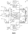
- FIG. 7 C is a schematic diagram of an RF communication system with interference cancellation according to another embodiment.
- FIG. 8 is a schematic diagram of an RF communication system with interference cancellation according to another embodiment.
- FIG. 9 is a schematic diagram of an RF communication system with interference cancellation according to another embodiment.
- FIG. 10 is a schematic diagram of an RF communication system with interference cancellation according to another embodiment.
- FIG. 11 A is a schematic diagram of an RF communication system with interference cancellation according to another embodiment.
- FIG. 11 B is a schematic diagram of an RF communication system with interference cancellation according to another embodiment.
- FIG. 12 is a schematic diagram of one embodiment of a mobile device with interference cancellation.
- FIG. 1 is a schematic diagram of one example of a mobile device 2 a communicating via cellular and WiFi networks.
- the mobile device 2 a communicates with a base station 1 of a cellular network and with a WiFi access point 3 of a WiFi network.
- FIG. 1 also depicts examples of other user equipment (UE) communicating with the base station 1 , for instance, a wireless-connected car 2 b and another mobile device 2 c .
- UE user equipment
- FIG. 1 also depicts examples of other WiFi-enabled devices communicating with the WiFi access point 3 , for instance, a laptop 4 .
- cellular UE and WiFi-enabled devices can communicate using cellular and/or WiFi networks.
- examples of such devices include, but are not limited to, mobile phones, tablets, laptops, Internet of Things (IoT) devices, wearable electronics, customer premises equipment (CPE), wireless-connected vehicles, wireless relays, and/or a wide variety of other communication devices.
- IoT Internet of Things
- CPE customer premises equipment
- a mobile device such as the mobile device 2 a of FIG. 1 , is implemented to support communications using a number of technologies, including, but not limited to, 2G, 3G, 4G (including LTE, LTE-Advanced, and LTE-Advanced Pro), 5G NR, WLAN (for instance, WiFi), WPAN (for instance, Bluetooth and ZigBee), WMAN (for instance, WiMax), and/or GPS.
- enhanced license assisted access eLAA is used to aggregate one or more licensed frequency carriers (for instance, licensed 4G LTE and/or 5G NR frequencies), with one or more unlicensed carriers (for instance, unlicensed WiFi frequencies).
- mobile devices can be implemented to support a wide range of communications.
- the communication links can be duplexed in a wide variety of ways, including, for example, using frequency-division duplexing (FDD) and/or time-division duplexing (TDD).
- FDD frequency-division duplexing
- TDD time-division duplexing
- FDD is a type of radio frequency communications that uses different frequencies for transmitting and receiving signals.
- FDD can provide a number of advantages, such as high data rates and low latency.
- TDD is a type of radio frequency communications that uses about the same frequency for transmitting and receiving signals, and in which transmit and receive communications are switched in time.
- TDD can provide a number of advantages, such as efficient use of spectrum and variable allocation of throughput between transmit and receive directions.
- frequency division multiple access is used to divide a frequency band into multiple frequency carriers. Additionally, one or more carriers are allocated to a particular user. Examples of FDMA include, but are not limited to, single carrier FDMA (SC-FDMA) and orthogonal FDMA (OFDMA). OFDMA is a multicarrier technology that subdivides the available bandwidth into multiple mutually orthogonal narrowband subcarriers, which can be separately assigned to different users.
- SC-FDMA single carrier FDMA
- OFDMA orthogonal FDMA
- OFDMA is a multicarrier technology that subdivides the available bandwidth into multiple mutually orthogonal narrowband subcarriers, which can be separately assigned to different users.
- shared access examples include, but are not limited to, time division multiple access (TDMA) in which a user is allocated particular time slots for using a frequency resource, code division multiple access (CDMA) in which a frequency resource is shared amongst different users by assigning each user a unique code, space-divisional multiple access (SDMA) in which beamforming is used to provide shared access by spatial division, and non-orthogonal multiple access (NOMA) in which the power domain is used for multiple access.
- TDMA time division multiple access
- CDMA code division multiple access
- SDMA space-divisional multiple access
- NOMA non-orthogonal multiple access
- NOMA can be used to serve multiple users at the same frequency, time, and/or code, but with different power levels.
- Radio frequency (RF) communication systems can include multiple transceivers for communicating using different wireless networks, over multiple frequency bands, and/or using different communication standards. Although implementing an RF communication system in this manner can expand functionality, increase bandwidth, and/or enhance flexibility, a number of coexistence issues can arise between the transceivers operating within the RF communication system.
- an RF communication system can include a cellular transceiver for processing RF signals communicated over a cellular network and a wireless local area network (WLAN) transceiver for processing RF signals communicated over a WLAN network, such as a WiFi network.
- WLAN wireless local area network
- the mobile device 2 a of FIG. 1 is operable to communicate using cellular and WiFi networks.
- a mutual desensitization effect can arise from cellular transmissions interfering with reception of WiFi signals and/or from WiFi transmissions interfering with reception of cellular signals.
- cellular Band 7 can give rise to mutual desensitization with respect to 2.4 Gigahertz (GHz) WiFi.
- Band 7 has an FDD duplex and operates over a frequency range of about 2.62 GHz to 2.69 GHz for downlink and over a frequency range of about 2.50 GHz to about 2.57 GHz for uplink
- 2.4 GHz WiFi has TDD duplex and operates over a frequency range of about 2.40 GHz to about 2.50 GHz.
- cellular Band 7 and 2.4 GHz WiFi are adjacent in frequency, and RF signal leakage due to the high power transmitter of one transceiver/front end affects receiver performance of the other transceiver/front end, particularly at border frequency channels.
- cellular Band 40 and 2.4 GHz WiFi can give rise to mutual desensitization.
- Band 40 has a TDD duplex and operates over a frequency range of about 2.30 GHz to about 2.40 GHz
- 2.4 GHz WiFi has TDD duplex and operates over a frequency range of about 2.40 GHz to about 2.50 GHz.
- cellular Band 40 and 2.4 GHz WiFi are adjacent in frequency and give rise to a number of coexistence issues, particularly at border frequency channels.
- cellular Band 41 and 2.4 GHz WiFi can also suffer from difficulties in coexisting.
- frequency separation between bands used for WiFi and cellular Band 40, 41 and 7 is so small that use of filters alone is insufficient for signal separation when WiFi and cellular communications are simultaneous.
- sensitivity of a WiFi receiver can be degraded by more than 40 dB in some cases due to the adjacent channel power level from the cellular transmitter.
- interference is exacerbated by increasing symbol rate, since higher symbol rate also leads to an increase in the bandwidth of adjacent power from the aggressor transmitter.
- a number of other factors can increase interference, including, but not limited to, closer antenna proximity, a greater degree of antenna sharing, an increase in the number of utilized frequency bands, a rise in the number of transceivers, inclusion of dual sim dual active (DSDA) features, and/or support for multiple-input multiple-output (MIMO) or diversity communications.
- DSDA dual sim dual active
- Desensitization can arise in a variety of ways, such as direct leakage of an aggressor transmit signal to a victim receiver, spectral regrowth components generated in the transmitter, and/or other interference sources. Such interference can lie relatively closely in frequency with the victim receive signal and/or directly overlap it. Although a receive filter can provide some filtering of signal leakage, the receive filter may provide insufficient attenuation of the aggressor signal, and thus the sensitivity of the victim receiver is degraded.
- a very high quality-factor (high Q) bandpass filter for instance, an acoustic bandpass filter
- an acoustic bandpass filter can be included at the output of a power amplifier of an aggressor transmitter to attenuate spectral regrowth.
- the attenuation provided by the filter is sufficiently high, the victim receiver may not be significantly desensitized due to non-linearity of the aggressor transmitter.
- high-Q bandpass filters can be prohibitively expensive and/or introduce insertion loss that degrades transmit performance.
- a very high Q bandpass filter can be included on the victim receiver to attenuate high power leakage coupled in from the aggressor transmitter.
- the victim receiver is not significantly desensitized from coupling of the high power leakage into non-linear receive circuitry of the victim receiver.
- high-Q bandpass filters can be prohibitively expensive and/or introduce insertion loss that degrades receiver sensitivity.
- an RF communication system includes a transmitter that transmits a transmit signal through a first front end system, a receiver that processes a receive signal from a second front end system, and an interference cancellation circuit that generates an interference cancellation signal that compensates the receiver for interference arising from the transmitter.
- the interference cancellation circuit includes a filter for filtering the transmit signal, a controllable phase circuit for adjusting a phase of the interference cancellation signal, and a controllable gain circuit for adjusting a gain of the interference cancellation signal.
- the interference cancellation schemes herein can reduce an amount of receiver filtering and/or transmitter filtering, thereby relaxing filter constraints and permitting the use of lower cost filters. Furthermore, receiver sensitivity and/or transmitter efficiency can be enhanced with little to no increase in power consumption and/or componentry to RF signal paths.
- the filter serves to suppress the aggressor carrier while passing a portion of the aggressor interfering with the victim receiver, such as adjacent channel leakage ratio (ACLR) noise.
- the filter couples noise to be cancelled into the interference cancellation circuit.
- the filter can serve to bleed off power of the transmitter over a limited range of frequencies, thereby leading to relative low loading loss. Moreover, the filter can relax constraints of RF front end filters and lead to a decreased component cost, lower system power consumption, and/or superior noise figure.
- the RF communication system for instance, UE, such as a mobile phone
- a directional coupler can be used without a filter to couple an aggressor signal, such directional couplers can lead to high loss in the transmit path, which can degrade transmit performance.
- noise figure can be relatively high due to high coupling loss, and a large amount of amplification may be needed to overcome loss, which can lead to a degradation in dynamic range.
- transmit insertion loss may be unacceptably high in order to avoid amplifying thermal noise. As a result, noise power can become larger than the signal desired to be cancelled when the coupler loss is low.
- the filter can be implemented in a wide variety of ways, which can vary based on application, implementation, and/or other considerations.
- the filter can be implemented using one or more bandpass filters, low pass filters, high pass filters, band rejection filters, or a combination thereof.
- the transmitter/first front end system can process RF signals of a different type than the receiver/second front end system.
- the transmitter/first front end system processes cellular signals while the receiver/second front end system processes WLAN signals, such as WiFi signals.
- the transmitter is included in a cellular transceiver, and the receiver is included in a WiFi transceiver.
- coexistence is provided between cellular and WiFi radios.
- RF communication systems including, but not limited to systems communicating using 4G, 5G NR, WLAN, WPAN, WMAN, and/or GPS signaling.
- RF communication systems can operate with a number of features, including, but not limited to, DSDA, MIMO, carrier aggregation, and/or diversity.
- FIG. 2 is a schematic diagram of one example of signal leakage for an RF communication system 70 .
- the RF communication system 70 includes a first transceiver 51 (including a first transmitter and a first receiver), a second transceiver 52 (including a second transmitter and a second receiver), a first front end system 53 , a second front end system 54 , a first antenna 55 , and a second antenna 56 .
- Including multiple transceivers, front end systems, and antennas enhances the flexibility of the RF communication system 70 .
- implementing the RF communication system 70 in this manner can allow the RF communication system 70 to communicate using different types of networks, for instance, cellular and WiFi networks.
- the first front end system 53 includes a transmit front end circuit 61 , a receive front end circuit 63 , and an antenna access circuit 65 , which can include one or more switches, duplexers, diplexers, triplexers, quadplexers, circulators, and/or other circuitry for controlling access of the transmit front end circuit 61 and the receive front end circuit 63 to the first antenna 55 .
- the second front end system 54 includes a transmit front end circuit 62 , a receive front end circuit 64 , and an antenna access circuit 66 .
- front end systems Although one example implementation of front end systems is shown in FIG. 2 , the teachings herein are applicable to front end systems implemented in a wide variety of ways. Accordingly, other implementations of front end systems are possible.
- RF signal leakage 69 between the first antenna 55 and the second antenna 56 can give rise to a number of coexistence issues.
- the interference cancellation schemes herein provide compensation to reduce or eliminate the impacts of such RF signal leakage.
- interference cancellation can also be provided in implementations using a shared antenna.
- FIG. 3 is a schematic diagram of one example of regrowth leakage for an RF communication system 90 .
- the RF communication system 90 includes a power amplifier 81 , a victim receiver 82 , a first antenna 83 , and a second antenna 84 .
- the power amplifier 81 receives an RF input signal, which is amplified by the power amplifier 81 to generate an RF output signal that is wirelessly transmitted using the first antenna 83 . Additionally, non-linearity of the power amplifier 81 gives rise to spectral regrowth in the RF output signal that is close in frequency to RF signals processed by the victim receiver 82 . Thus, regrowth leakage from the RF output signal gives rise to a degradation in receiver sensitivity.
- any suitable type of interference can be cancelled in accordance with the teachings herein.
- spectral regrowth is compensated.
- direct transmit leakage is compensated.
- harmonic interference for instance, harmonics falling on a victim receive band
- FIG. 4 is a schematic diagram of an RF communication system 100 with interference cancellation according to one embodiment.
- the RF communication system 100 includes a transmitter 91 , a receiver 92 , a transmit front end circuit 93 , a receive front end circuit 94 , and an interference cancellation circuit 95 .
- the transmitter 91 operates to transmit a transmit signal through the transmit front end circuit 93 . Additionally, the receiver 92 processes a receive signal from the receive front end circuit 94 .
- the interference cancellation circuit 95 includes a filter 96 , a controllable phase circuit 97 , and a controllable gain circuit 98 .
- the interference cancellation circuit 95 generates an interference cancellation signal that compensates the receiver 92 for interference arising from the transmitter 91 .
- the filter 96 filters the transmit signal to inject a desired portion of the frequency spectrum of the transmit signal into the interference cancellation circuit 95 .
- the controllable phase circuit 97 and controllable gain circuit 98 provide phase and gain adjustment, respectively, to achieve a proper polarity and amplitude of the interference cancellation signal for interference cancellation.
- FIG. 5 is a schematic diagram of an RF communication system 140 with interference cancellation according to another embodiment.
- the RF communication system 140 includes a cellular transmitter 121 , a cellular receiver 122 , a WiFi transmitter 123 , a WiFi receiver 124 , a cellular duplexer 125 , a WiFi transmit/receive switch 126 , a triplexer 127 , a shared antenna 128 , and an interference cancellation circuit 135 .
- the WiFi receiver 124 includes a WiFi receive filter 129 , a WiFi LNA 130 , and a signal combiner 131 .
- the interference cancellation circuit 135 includes a bandpass filter 136 , a controllable phase shifter 137 , and a controllable attenuator 138 .
- the bandpass filter 136 serves to provide filtering to obtain a portion of the transmit signal desired for cancellation.
- the bandpass filter 136 passes spectral regrowth in the WiFi receive band while blocking a carrier frequency of the cellular transmit signal from the cellular transmitter 121 .
- the interference cancellation signal is provided with a relatively high amplitude at the output of the WiFi LNA 130 such that the signal is well above the noise floor.
- WiFi sensitivity can be reduced only by a relatively small amount, for instance, 0.03 dB at 18 dB of LNA gain and 0.11 dB at 12 dB of LNA gain when the signal combiner 131 is implemented as a 3 dB coupler.
- FIG. 6 A is a schematic diagram of a simulation setup 150 for an interference cancellation circuit 135 according to one embodiment.
- the interference cancellation circuit 135 includes a bandpass filter 136 , a controllable phase shifter 137 , and a controllable attenuation circuit 138 .
- the simulation setup 150 includes a first impedance 141 representing impedance of a cellular transmitter, a second impedance 142 representing impedance of a cellular receiver, a cellular duplexer 125 (Band 7, in this example), a WiFi directional coupler 145 , a third impedance 143 representing a coupler termination, and a fourth impedance 144 representing impedance of a WiFi receiver.
- the bandpass filter 136 detects the aggressor signal to be cancelled without suffering from coupler loss in the cellular transmit path.
- the cancellation signal is provided from the interference cancellation circuit 135 to the WiFi directional coupler 145 .
- other implementations are possible.
- FIG. 6 B is a schematic diagram of one example of gain versus frequency simulations for the interference cancellation circuit 135 of FIG. 6 A .
- the simulations include an upper graph and a lower graph.
- the upper graph includes a portion 149 depicting the impact in the frequency domain of the cancellation with respect to the bandwidth of the bandpass filter 136 .
- FIG. 6 C is a schematic diagram of one example of frequency spectrum characteristics for the interference cancellation circuit of FIG. 6 A .
- the WiFi bandpass filter 136 is implemented with a passband that rejects a Band 7 carrier frequency while passing spectral regrowth that serves to interfere with reception of WiFi signals.
- FIG. 7 A is a schematic diagram of an RF communication system 290 with interference cancellation according to another embodiment.
- the RF communication system 290 includes a cellular transceiver 201 (including a cellular transmitter and a first cellular receiver), a second cellular receiver 202 , a third cellular receiver 203 , a fourth cellular receiver 204 , a first WiFi transmitter 211 , a second WiFi transmitter 212 , a first WiFi receiver 221 , a second WiFi receiver 222 , an antenna switch 230 , a first antenna 231 , a second antenna 232 , a third antenna 233 , a fourth antenna 234 , a cellular directional coupler 240 , a first WiFi extractor 241 , a second WiFi extractor 242 , a first WiFi transmit/receive switch 243 , a second WiFi transmit/receive switch 244 , a first signal combiner 245 , a second signal combiner 246 , and an interference cancellation circuit 255 .
- the interference cancellation circuit 255 includes a first multi-throw switch 261 , a second multi-throw switch 262 , a first filter 263 , a second filter 264 , a third filter 265 , a shared controllable amplifier 270 , a first separately controllable amplifier 271 , a second separately controllable amplifier 272 , a first controllable phase shifter 281 , and a second controllable phase shifter 282 .
- a first multi-throw switch 261 a second multi-throw switch 262 , a first filter 263 , a second filter 264 , a third filter 265 , a shared controllable amplifier 270 , a first separately controllable amplifier 271 , a second separately controllable amplifier 272 , a first controllable phase shifter 281 , and a second controllable phase shifter 282 .
- the teachings herein are applicable to interference cancellation circuits implemented in a wide variety of ways.
- the interference cancellation circuit 255 generates separate interference cancellation signals for the first WiFi receiver 221 and the second WiFi receiver 222 , in this embodiment.
- an interference cancellation circuit provides interference cancellation to two or more receivers. As shown in FIG. 7 A , the gain and phase of each interference cancellation signal is separately controllable, thereby providing precision cancellation to correctly compensate for an amount of interference present at the input of each WiFi receiver.
- the interference cancellation circuit 255 also includes the shared controllable amplifier 270 for providing common gain adjustment to the first and second interference compensation signals.
- gain and/or phase of two or more interference cancellation signals can be commonly controlled in all or part.
- the interference cancellation circuit 255 also includes multiple selectable filters, in this embodiment.
- the selected filter can be chosen based on a transmit frequency band of the cellular transmitter 201 .
- the first filter 283 can be selected when transmitting Band 7
- the second filter 284 can be selected when transmitting Band 40
- the third filter 285 can be selected when transmitting Band 41.
- the first filter 283 , the second filter 284 , and the third filter 285 can have filter characteristics selected to receive a desired portion of the transmit signal suitable for cancellation. For example, in certain implementations, a carrier frequency of the transmit signal is rejected while ALCR noise is passed. For instance, FIG. 6 C illustrates one example of a filter characteristic for the first filter 283 . However, other implementations are possible.
- the first signal combiner 245 and the second signal combiner 246 are positioned at the inputs to the first WiFi receiver 221 and the second WiFi receiver 222 , respectively.
- other implementations are possible.
- the interference cancellation circuit 255 receives the transmit signal via the transmit path coupler 240 .
- the transmit path coupler 240 is omitted.
- FIG. 7 B is a schematic diagram of an RF communication system 310 with interference cancellation according to another embodiment.
- the RF communication system 310 includes a cellular transceiver 201 , a second cellular receiver 202 , a third cellular receiver 203 , a fourth cellular receiver 204 , a first WiFi transmitter 211 , a second WiFi transmitter 212 , a first WiFi receiver 291 , a second WiFi receiver 292 , an antenna switch 230 , a first antenna 231 , a second antenna 232 , a third antenna 233 , a fourth antenna 234 , a first WiFi extractor 241 , a second WiFi extractor 242 , a first WiFi transmit/receive switch 243 , a second WiFi transmit/receive switch 244 , and an interference cancellation circuit 305 .
- the first WiFi receiver 291 includes a first WiFi receive filter 293 , a first WiFi LNA 295 , and a first signal combiner 245
- the second WiFi receiver 292 includes a second WiFi receive filter 294 , a second WiFi LNA 296 , and a second signal combiner 246 . Accordingly, the interference cancellation signals are provided after the LNAs, in this embodiment.
- Injecting the interference cancellation signals after the LNAs provides a number of advantages, such as relaxed dynamic range constraints.
- the interference cancellation circuit 305 includes a first multi-throw switch 261 , a second multi-throw switch 262 , a first filter 263 , a second filter 264 , a third filter 265 , a shared amplifier 300 , a first controllable attenuator 301 , a second controllable attenuator 302 , a first controllable phase shifter 281 , and a second controllable phase shifter 282 .
- the interference cancellation circuit 305 illustrates another embodiment of an interference cancellation circuit suitable for providing interference cancellation to multiple receivers.
- teachings herein are applicable to interference cancellation circuits implemented in a wide variety of ways.
- FIG. 7 C is a schematic diagram of an RF communication system 320 with interference cancellation according to another embodiment.
- the RF communication system 320 includes a cellular transceiver 201 , a second cellular receiver 202 , a third cellular receiver 203 , a fourth cellular receiver 204 , a first WiFi transmitter 211 , a second WiFi transmitter 212 , a first WiFi receiver 311 , a second WiFi receiver 312 , an antenna switch 230 , a first antenna 231 , a second antenna 232 , a third antenna 233 , a fourth antenna 234 , a first WiFi extractor 241 , a second WiFi extractor 242 , a first WiFi transmit/receive switch 243 , a second WiFi transmit/receive switch 244 , and an interference cancellation circuit 315 .
- the first WiFi receiver 311 includes a first WiFi receive filter 293 and a first WiFi LNA 317
- the second WiFi receiver 312 includes a second WiFi receive filter 294 and a second WiFi LNA 318 .
- the interference cancellation signals are provided into the LNAs, in this embodiment.
- the interference cancellation signals can be injected between stages of the LNA, using gain transistors that operate in parallel to transistors used for signal amplification, and/or in a wide variety of other ways.
- Injecting the interference cancellation circuits into the LNAs can provide a number of advantages, such as relaxed linearity constraints of the LNAs.
- the interference cancellation circuit 315 includes a first multi-throw switch 261 , a second multi-throw switch 262 , a first filter 263 , a second filter 264 , a third filter 265 , a Wilkinson splitter 314 , a first controllable attenuator 301 , a second controllable attenuator 302 , a first controllable phase shifter 281 , and a second controllable phase shifter 282 .
- the interference cancellation circuit 315 illustrates another embodiment of an interference cancellation circuit suitable for providing interference cancellation to multiple receivers.
- teachings herein are applicable to interference cancellation circuits implemented in a wide variety of ways.
- FIG. 8 is a schematic diagram of an RF communication system 350 with interference cancellation according to another embodiment.
- the RF communication system 350 includes a cellular transceiver 201 , a second cellular receiver 202 , a third cellular receiver 203 , a fourth cellular receiver 204 , a first WiFi transmitter 211 , a second WiFi transmitter 212 , a first WiFi receiver 321 , a second WiFi receiver 322 , an antenna switch 230 , a first antenna 231 , a second antenna 232 , a third antenna 233 , a fourth antenna 234 , a first WiFi extractor 241 , a second WiFi extractor 242 , a first WiFi transmit/receive switch 243 , a second WiFi transmit/receive switch 244 , an interference cancellation circuit 325 , and a radio access unit (RAU) 328 .
- RAU radio access unit
- the first WiFi receiver 321 of FIG. 8 is similar to the first WiFi receiver 311 of FIG. 7 C , except that the first WiFi receiver 321 further includes a WiFi baseband (BB) co-channel circuit 341 for communication with the RAU 328 .
- the second WiFi receiver 322 of FIG. 8 is similar to the second WiFi receiver 312 of FIG. 7 C , except that the second WiFi receiver 322 further includes a WiFi BB co-channel circuit 342 for communication with the RAU 328 .
- the RAU 328 controls the interference cancellation circuit 325 , for instance, to set gain and/or phase adjustment values for interference cancellation.
- signal to noise ratio is measured or sensed at a victim receiver and used to tune the attenuators and/or phase shifters of the interference cancellation circuit 325 to enhance the accuracy of interference cancellation.
- the interference cancellation circuit 325 includes a diplexer 330 , a first amplifier 331 , a second amplifier 332 , a first controllable attenuator 333 , a second controllable attenuator 334 , a first controllable phase shifter 335 , and a second controllable phase shifter 336 .
- the first amplifier 331 and the second amplifier 332 serves as buffers to isolate the branches used for interference cancellation. When a gain of the first amplifier 331 and the second amplifier 332 is sufficiently high, the noise figure is low and a relatively small and cost effective solution is achieved.
- the interference cancellation circuit 325 illustrates another embodiment of an interference cancellation circuit suitable for providing interference cancellation to multiple receivers.
- teachings herein are applicable to interference cancellation circuits implemented in a wide variety of ways.
- FIG. 9 is a schematic diagram of an RF communication system 390 with interference cancellation according to another embodiment.
- the RF communication system 390 includes a cellular transceiver 201 , a second cellular receiver 202 , a third cellular receiver 203 , a fourth cellular receiver 204 , a first WiFi transmitter 211 , a second WiFi transmitter 212 , a first WiFi receiver 221 , a second WiFi receiver 222 , an antenna switch 230 , a first antenna 231 , a second antenna 232 , a third antenna 233 , a fourth antenna 234 , a first WiFi extractor 241 , a second WiFi extractor 242 , a first WiFi transmit/receive switch 243 , a second WiFi transmit/receive switch 244 , a first signal combiner 245 , a second signal combiner 246 , and an interference cancellation circuit 335 .
- the interference cancellation circuit 335 includes a filter 343 , a Wilkinson splitter 346 , a first controllable phase shifter 281 , a second controllable phase shifter 282 , a first controllable attenuator 301 , and a second controllable attenuator 302 .
- the interference cancellation circuit 335 illustrates another embodiment of an interference cancellation circuit suitable for providing interference cancellation to multiple receivers.
- teachings herein are applicable to interference cancellation circuits implemented in a wide variety of ways.
- FIG. 10 is a schematic diagram of an RF communication system 400 with interference cancellation according to another embodiment.
- the RF communication system 400 includes a cellular transceiver 201 , a second cellular receiver 202 , a first WiFi transmitter 211 , a second WiFi transmitter 212 , a first WiFi receiver 221 , a second WiFi receiver 222 , an antenna switch 230 , a first antenna 231 , a second antenna 232 , a cellular directional coupler 240 , a first WiFi extractor 241 , a second WiFi extractor 242 , a first WiFi transmit/receive switch 243 , a second WiFi transmit/receive switch 244 , a first signal combiner 245 , a second signal combiner 246 , and an interference cancellation circuit 255 .
- the RF communication system 400 of FIG. 10 is similar to the RF communication system 290 of FIG. 7 A , except that the RF communication system 400 illustrates an implementation with fewer cellular receivers and antennas.
- the teachings herein are applicable to RF communication systems implemented in a wide variety of ways.
- an RF communication system can be implemented with downlink MIMO, uplink MIMO, downlink diversity, uplink diversity, beamforming, shared antennas, separate antennas, and/or a range of other features.
- FIG. 11 A is a schematic diagram of an RF communication system 540 with interference cancellation according to another embodiment.
- the RF communication system 540 includes a cellular power amplifier 501 , a cellular LNA 502 , a cellular duplexer 503 , a cellular directional coupler 504 , a coupler termination impedance 505 , a cellular antenna 510 , a first WiFi antenna 511 , a second WiFi antenna 512 , a first WiFi receiver 513 , a second WiFi receiver 514 , a first signal combiner 515 , a second signal combiner 516 , and an interference cancellation circuit 525 .
- the interference cancellation circuit 525 includes a filter 531 , a shared controllable amplifier 532 , a first separately controllable amplifier 533 , a second separately controllable amplifier 534 , a first controllable phase shifter 535 , and a second controllable phase shifter 536 .
- the RF communication system 540 of FIG. 11 A illustrates yet another embodiment of an RF communication system with interference cancellation.
- teachings herein are applicable to RF communication systems implemented in a wide variety of ways.
- FIG. 11 B is a schematic diagram of an RF communication system 550 with interference cancellation according to another embodiment.
- the RF communication system 550 includes a cellular power amplifier 501 , a cellular LNA 502 , a cellular duplexer 503 , a cellular directional coupler 504 , a coupler termination impedance 505 , a first WiFi receiver 513 , a second WiFi receiver 514 , a first signal combiner 515 , a second signal combiner 516 , an interference cancellation circuit 525 , a triplexer 541 , and a shared antenna 542 .
- the RF communication system 550 of FIG. 11 B illustrates yet another embodiment of an RF communication system with interference cancellation.
- teachings herein are applicable to RF communication systems implemented in a wide variety of ways.
- FIG. 12 is a schematic diagram of one embodiment of a mobile device 800 with interference cancellation.
- the mobile device 800 includes a digital processing system 801 , a first transceiver 802 , a second transceiver 812 , a first front end system 803 , a second front end system 813 , a first antenna 804 , a second antenna 814 , a power management system 805 , a memory 806 , a user interface 807 , and an interference cancellation circuit 95 .
- the interference cancellation circuit 95 includes a filter 96 , a controllable phase circuit 97 , and a controllable gain circuit 98 .
- the interference cancellation circuit 95 can be implemented in accordance with any of the embodiments herein.
- the mobile device 800 can be used communicate using a wide variety of communications technologies, including, but not limited to, 2G, 3G, 4G (including LTE, LTE-Advanced, and LTE-Advanced Pro), 5G NR, WLAN (for instance, WiFi), WPAN (for instance, Bluetooth and ZigBee), WMAN (for instance, WiMax), and/or GPS technologies.
- 2G, 3G, 4G including LTE, LTE-Advanced, and LTE-Advanced Pro
- 5G NR for instance, WLAN (for instance, WiFi), WPAN (for instance, Bluetooth and ZigBee), WMAN (for instance, WiMax), and/or GPS technologies.
- the digital processing circuit 801 includes a first baseband modem 821 and a second baseband modem 822 .
- the first baseband modem 821 and the second baseband modem 822 control communications associated with different types of wireless communications, for instance, cellular and WiFi.
- the first baseband modem 821 , the first transceiver 802 , and the first front end system 803 operate to transmit and receive RF signals using the first antenna 804 .
- the second baseband modem 822 , the second transceiver 812 , and the second front end system 813 operate to transmit and receive RF signals using the second antenna 814 .
- the mobile device 800 can include additional antennas including, but not limited to, multiple antennas for cellular communications and/or multiple antenna for WiFi communications.
- the first front end system 803 operates to condition RF signals transmitted by and/or received from the first antenna 804 . Additionally, the second front end system 804 operates to condition RF signals transmitted by and/or received from the second antenna 814 .
- the front end systems can provide a number of functionalities, including, but not limited to, amplifying signals for transmission, amplifying received signals, filtering signals, switching between different bands, switching between different power modes, switching between transmission and receiving modes, duplexing of signals, multiplexing of signals (for instance, diplexing or triplexing), or some combination thereof.
- the mobile device 800 supports carrier aggregation, thereby providing flexibility to increase peak data rates.
- Carrier aggregation can be used for both Frequency Division Duplexing (FDD) and Time Division Duplexing (TDD), and may be used to aggregate a plurality of carriers or channels.
- Carrier aggregation includes contiguous aggregation, in which contiguous carriers within the same operating frequency band are aggregated.
- Carrier aggregation can also be non-contiguous, and can include carriers separated in frequency within a common band or in different bands.
- the first antenna 804 and the second antenna 814 can include antenna elements implemented in a wide variety of ways.
- the antenna elements are arranged to form one or more antenna arrays. Examples of antenna elements include, but are not limited to, patch antennas, dipole antenna elements, ceramic resonators, stamped metal antennas, and/or laser direct structuring antennas.
- the mobile device 800 supports MIMO communications and/or switched diversity communications.
- MIMO communications use multiple antennas for communicating multiple data streams over a single radio frequency channel.
- MIMO communications benefit from higher signal to noise ratio, improved coding, and/or reduced signal interference due to spatial multiplexing differences of the radio environment.
- Switched diversity refers to communications in which a particular antenna is selected for operation at a particular time.
- a switch can be used to select a particular antenna from a group of antennas based on a variety of factors, such as an observed bit error rate and/or a signal strength indicator.
- the mobile device 800 operates with beamforming.
- the first front end system 803 and/or the second front end system 813 can include phase shifters having variable phase to provide beam formation and directivity for transmission and/or reception of signals.
- the phases of the transmit signals provided to an antenna array used for transmission are controlled such that radiated signals combine using constructive and destructive interference to generate an aggregate transmit signal exhibiting beam-like qualities with more signal strength propagating in a given direction.
- the phases are controlled such that more signal energy is received when the signal is arriving to the antenna array from a particular direction.
- the mobile device 800 of FIG. 12 illustrates one embodiment of a mobile device implemented with interference cancellation. Although one example of a mobile device is shown, the teachings herein are applicable a wide range of with interference cancellation schemes.
- the digital processing system 801 is coupled to the user interface 807 to facilitate processing of various user input and output (I/O), such as voice and data.
- the digital processing system 801 provides the transceivers with digital representations of transmit signals, which are processed by the transceivers to generate RF signals for transmission.
- the digital processing system 801 also processes digital representations of received signals provided by the transceivers.
- the digital processing system 801 is coupled to the memory 806 of facilitate operation of the mobile device 800 .
- the memory 806 can be used for a wide variety of purposes, such as storing data and/or instructions to facilitate the operation of the mobile device 800 and/or to provide storage of user information.
- the power management system 805 provides a number of power management functions of the mobile device 800 .
- the power management system 805 includes a PA supply control circuit that controls the supply voltages of the power amplifiers of the front end systems.
- the power management system 805 can be configured to change the supply voltage(s) provided to one or more of the power amplifiers to improve efficiency, such as power added efficiency (PAE).
- PAE power added efficiency
- the power management system 805 receives a battery voltage from a battery.
- the battery can be any suitable battery for use in the mobile device 800 , including, for example, a lithium-ion battery.
- RF communication systems include, but are not limited to, mobile phones, tablets, base stations, network access points, customer-premises equipment (CPE), laptops, and wearable electronics.
- CPE customer-premises equipment
- the words “comprise,” “comprising,” and the like are to be construed in an inclusive sense, as opposed to an exclusive or exhaustive sense; that is to say, in the sense of “including, but not limited to.”
- the word “coupled”, as generally used herein, refers to two or more elements that may be either directly connected, or connected by way of one or more intermediate elements.
- the word “connected”, as generally used herein, refers to two or more elements that may be either directly connected, or connected by way of one or more intermediate elements.
- the words “herein,” “above,” “below,” and words of similar import when used in this application, shall refer to this application as a whole and not to any particular portions of this application.
- words in the above Detailed Description using the singular or plural number may also include the plural or singular number respectively.
- conditional language used herein such as, among others, “may,” “could,” “might,” “can,” “e.g.,” “for example,” “such as” and the like, unless specifically stated otherwise, or otherwise understood within the context as used, is generally intended to convey that certain embodiments include, while other embodiments do not include, certain features, elements and/or states.
- conditional language is not generally intended to imply that features, elements and/or states are in any way required for one or more embodiments or that one or more embodiments necessarily include logic for deciding, with or without author input or prompting, whether these features, elements and/or states are included or are to be performed in any particular embodiment.
Abstract
Description
Claims (20)
Priority Applications (3)
| Application Number | Priority Date | Filing Date | Title |
|---|---|---|---|
| US16/738,834 US11558079B2 (en) | 2019-01-15 | 2020-01-09 | Radio frequency communication systems with interference cancellation for coexistence |
| US17/822,393 US11742890B2 (en) | 2019-01-15 | 2022-08-25 | Radio frequency communication systems with interference cancellation for coexistence |
| US18/365,440 US20240022284A1 (en) | 2019-01-15 | 2023-08-04 | Radio frequency communication systems with interference cancellation for coexistence |
Applications Claiming Priority (2)
| Application Number | Priority Date | Filing Date | Title |
|---|---|---|---|
| US201962792508P | 2019-01-15 | 2019-01-15 | |
| US16/738,834 US11558079B2 (en) | 2019-01-15 | 2020-01-09 | Radio frequency communication systems with interference cancellation for coexistence |
Related Child Applications (1)
| Application Number | Title | Priority Date | Filing Date |
|---|---|---|---|
| US17/822,393 Continuation US11742890B2 (en) | 2019-01-15 | 2022-08-25 | Radio frequency communication systems with interference cancellation for coexistence |
Publications (2)
| Publication Number | Publication Date |
|---|---|
| US20200228159A1 US20200228159A1 (en) | 2020-07-16 |
| US11558079B2 true US11558079B2 (en) | 2023-01-17 |
Family
ID=71516950
Family Applications (3)
| Application Number | Title | Priority Date | Filing Date |
|---|---|---|---|
| US16/738,834 Active US11558079B2 (en) | 2019-01-15 | 2020-01-09 | Radio frequency communication systems with interference cancellation for coexistence |
| US17/822,393 Active US11742890B2 (en) | 2019-01-15 | 2022-08-25 | Radio frequency communication systems with interference cancellation for coexistence |
| US18/365,440 Pending US20240022284A1 (en) | 2019-01-15 | 2023-08-04 | Radio frequency communication systems with interference cancellation for coexistence |
Family Applications After (2)
| Application Number | Title | Priority Date | Filing Date |
|---|---|---|---|
| US17/822,393 Active US11742890B2 (en) | 2019-01-15 | 2022-08-25 | Radio frequency communication systems with interference cancellation for coexistence |
| US18/365,440 Pending US20240022284A1 (en) | 2019-01-15 | 2023-08-04 | Radio frequency communication systems with interference cancellation for coexistence |
Country Status (1)
| Country | Link |
|---|---|
| US (3) | US11558079B2 (en) |
Cited By (8)
| Publication number | Priority date | Publication date | Assignee | Title |
|---|---|---|---|---|
| US20220159585A1 (en) * | 2020-11-18 | 2022-05-19 | Facebook Technologies, Llc | Systems and methods of configuring a spectral mask |
| US11736133B2 (en) | 2018-08-21 | 2023-08-22 | Skyworks Solutions, Inc. | Coexistence management for radio frequency communication systems |
| US11736132B2 (en) | 2018-08-21 | 2023-08-22 | Skyworks Solutions, Inc. | Radio frequency communication systems with coexistence management based on digital observation data |
| US11736141B2 (en) | 2018-08-21 | 2023-08-22 | Skyworks Solutions, Inc. | Discrete time cancellation for providing coexistence in radio frequency applications |
| US11736140B2 (en) | 2019-09-27 | 2023-08-22 | Skyworks Solutions, Inc. | Mixed signal low noise interference cancellation |
| US11742890B2 (en) | 2019-01-15 | 2023-08-29 | Skyworks Solutions, Inc. | Radio frequency communication systems with interference cancellation for coexistence |
| US11784419B2 (en) | 2019-09-27 | 2023-10-10 | Skyworks Solutions, Inc. | Antenna-plexer for interference cancellation |
| US11888502B2 (en) | 2021-04-07 | 2024-01-30 | Skyworks Solutions, Inc. | Systems and methods for duplexer circuits having signal leakage cancellation |
Families Citing this family (5)
| Publication number | Priority date | Publication date | Assignee | Title |
|---|---|---|---|---|
| US11515608B2 (en) | 2019-02-27 | 2022-11-29 | Skyworks Solutions, Inc. | Remote compensators for mobile devices |
| CN114070420B (en) * | 2020-07-31 | 2023-04-07 | 华为技术有限公司 | Anti-interference electronic equipment and anti-interference method |
| WO2022195789A1 (en) * | 2021-03-18 | 2022-09-22 | 三菱電機株式会社 | Canceler device and wireless device |
| US11356133B1 (en) * | 2021-04-30 | 2022-06-07 | Hewlett Packard Enterprise Development Lp | Methods and systems for filter frequency response shift compensation for WLAN traffic |
| US11606228B2 (en) | 2021-04-30 | 2023-03-14 | Hewlett Packard Enterprise Development Lp | Methods and systems for filter frequency response shift compensation for WLAN traffic |
Citations (114)
| Publication number | Priority date | Publication date | Assignee | Title |
|---|---|---|---|---|
| US4902992A (en) | 1988-03-29 | 1990-02-20 | The United States Of America As Represented By The Secretary Of The Navy | Millimeter-wave multiplexers |
| US6101228A (en) | 1997-05-22 | 2000-08-08 | Conexant Systems, Inc. | Receiver of wideband digital signal in the presence of a narrow band interfering signal |
| US6226322B1 (en) | 1998-03-30 | 2001-05-01 | Texas Instruments Incorporated | Analog receive equalizer for digital-subscriber-line communications system |
| US20010008383A1 (en) | 2000-01-18 | 2001-07-19 | Sanyo Electric Co., Ltd. | Feedback circuit and amplifier and mixer comprising the same |
| US20010033119A1 (en) | 1999-01-14 | 2001-10-25 | The Regents Of The University Of Michigan | Method and subsystem for processing signals utilizing a plurality of vibrating micromechanical devices |
| US20030185309A1 (en) | 2001-04-07 | 2003-10-02 | Pautler Joseph J. | Method and system in a transceiver for controlling a multiple-input, multiple-output communications channel |
| WO2004095763A2 (en) | 2003-04-07 | 2004-11-04 | Widefi, Inc. | Transmission canceller for wireless local area network repeater |
| US20050020297A1 (en) | 2003-05-27 | 2005-01-27 | Interdigital Technology Corporation | Multi-mode radio with interference cancellation circuit |
| US6965657B1 (en) | 1999-12-01 | 2005-11-15 | Velocity Communication, Inc. | Method and apparatus for interference cancellation in shared communication mediums |
| US7146133B2 (en) | 2003-06-19 | 2006-12-05 | Microsoft Corporation | Wireless transmission interference avoidance on a device capable of carrying out wireless network communications |
| US7305216B2 (en) | 2004-05-25 | 2007-12-04 | Infineon Technologies Ag | Transmitting and receiving arrangement with interference signal suppression control |
| US20080089397A1 (en) | 2006-10-17 | 2008-04-17 | Interdigital Technology Corporation | Transceiver with hybrid adaptive self-interference canceller for removing transmitter generated noise to prevent modem jamming |
| US20080181337A1 (en) | 2007-01-31 | 2008-07-31 | Silicon Laboratories, Inc. | Spur and Distortion Management Techniques for an RF Receiver |
| US7412217B2 (en) | 2004-04-22 | 2008-08-12 | Infineon Technologies Ag | Transceiver with interference signal rejection, and method for interference signal rejection |
| US20080219377A1 (en) | 2007-03-06 | 2008-09-11 | Sige Semiconductor Inc. | Transmitter crosstalk cancellation in multi-standard wireless transceivers |
| US20090161801A1 (en) | 2007-12-24 | 2009-06-25 | Industrial Technology Research Institute | Receiver with discrete-time filtering and down-conversion |
| US7565112B2 (en) | 2006-03-02 | 2009-07-21 | Freescale Semiconductor, Inc. | Reduced adjacent channel interference in a radio receiver |
| CN101512919A (en) | 2006-09-01 | 2009-08-19 | 高通股份有限公司 | Repeater having dual receiver or transmitter antenna configuration with adaptation for increased isolation |
| US7620373B2 (en) | 2006-06-23 | 2009-11-17 | Sierra Monolithics, Inc. | Apparatus and method for calibration of gain and/or phase imbalance and/or DC offset in a communication system |
| US20100246557A1 (en) | 2007-09-20 | 2010-09-30 | Haruya Ishizaki | Receiver apparatus and reception method |
| US20110205986A1 (en) | 2010-02-25 | 2011-08-25 | Kameswara Rao Medapalli | Method and System for a Time Domain Approach to 4G WiMAX/LTE-WiFi/BT Coexistence |
| US20110227642A1 (en) | 2010-03-16 | 2011-09-22 | Motorola, Inc. | Parallel forward path cartesian feedback loop and loop filter with switchable order for cartesian feedback loops |
| US8121573B2 (en) | 2008-08-12 | 2012-02-21 | Broadcom Corporation | Method and system for coexistence in a multiband, multistandard communication system utilizing a plurality of phase locked loops |
| US20120182896A1 (en) | 2011-01-18 | 2012-07-19 | Samsung Electronics Co. Ltd. | Interference measurement method and apparatus for user equipment having multiple heterogeneous communication modules in wireless communication system |
| WO2012098754A1 (en) | 2011-01-19 | 2012-07-26 | 三菱電機株式会社 | Output-mode switching amplifier |
| US20120214426A1 (en) | 2010-12-30 | 2012-08-23 | Intel Mobile Communications GmbH | Rf feedback receiver arrangement, rf transmit arrangement and rf transceiver arrangement |
| US20120281550A1 (en) | 2010-01-20 | 2012-11-08 | Huawei Technologies Co., Ltd. | Receiver, transmitter, feedback device, transceiver and signal processing method |
| US8325865B1 (en) | 2011-07-31 | 2012-12-04 | Broadcom Corporation | Discrete digital receiver |
| US20130102254A1 (en) | 2010-05-27 | 2013-04-25 | Ubiquam Ltd. | Method and system of interference cancelation in collocated transceivers configurations |
| US20130114583A1 (en) | 2011-11-04 | 2013-05-09 | Sharp Laboratories Of America, Inc. | In-device coexistence interference avoidance (idc) |
| US20130259099A1 (en) | 2012-03-30 | 2013-10-03 | Qualcomm Incorporated | Tunable notch filter using feedback through an existing feedback receiver |
| US8553610B2 (en) | 2011-05-12 | 2013-10-08 | Qualcomm Incorporated | Interference cancellation repeater incorporating a non-linear element |
| US8553622B2 (en) | 2009-12-04 | 2013-10-08 | Zte Corporation | Apparatus and method for suppressing interference caused by coexistence of WiMAX and WiFi |
| US8599709B2 (en) | 2011-02-10 | 2013-12-03 | Apple Inc. | Methods and apparatus for wireless coexistence based on transceiver chain emphasis |
| US20140003300A1 (en) | 2012-06-29 | 2014-01-02 | Qualcomm Incorporated | Antenna interface circuits for carrier aggregation on multiple antennas |
| US8681748B2 (en) | 2010-08-17 | 2014-03-25 | Broadcom Corporation | Wireless transceivers with filter arrangement for WiFi and WiMAX coexsistence |
| US8706032B2 (en) | 2007-04-10 | 2014-04-22 | Marvell World Trade Ltd. | Systems and methods for providing collaborative coexistence between Bluetooth and Wi-Fi |
| US8750926B2 (en) | 2010-06-18 | 2014-06-10 | Mediatek Inc. | System and method for coordinating multiple radio transceivers within the same device platform |
| US20140161159A1 (en) | 2012-12-12 | 2014-06-12 | Motorola Mobility Llc | Method and apparatus for the cancellation of intermodulation and harmonic distortion in a baseband receiver |
| US8767869B2 (en) | 2011-08-18 | 2014-07-01 | Qualcomm Incorporated | Joint linear and non-linear cancellation of transmit self-jamming interference |
| US20140194071A1 (en) | 2013-01-04 | 2014-07-10 | Telefonaktiebolaget L M Ericsson (Publ) | Transmitter noise suppression in receiver |
| US20140269858A1 (en) | 2013-03-13 | 2014-09-18 | Analog Devices Technology | Transmitter noise cancellation in a multi transmitter-receiver system |
| US20140269852A1 (en) | 2013-03-13 | 2014-09-18 | Analog Devices Technology | Radio frequency transmitter noise cancellation |
| US8842546B2 (en) | 2010-07-22 | 2014-09-23 | Mediatek Inc. | Method for wireless communication in a device with co-existence radio |
| US20140301498A1 (en) | 2013-04-05 | 2014-10-09 | Qualcomm Incorporated | Non-linear Interference Cancellation Across Aggressor Transmitters and Victim Receivers |
| US20140341196A1 (en) | 2012-03-06 | 2014-11-20 | Huawei Device Co., Ltd. | Transmission Method, System, and Communication Device for Realizing Coexistence of Data and Voice Services |
| WO2014195830A1 (en) | 2013-06-05 | 2014-12-11 | Telefonaktiebolaget L M Ericsson (Publ) | Digital predistortion of wideband power amplifiers with reduced observation bandwidth |
| US8934362B2 (en) | 2011-01-06 | 2015-01-13 | Mediatek Inc. | Power control method to mitigate interference for in-device coexistence |
| US20150065064A1 (en) * | 2013-08-30 | 2015-03-05 | Qualcomm Incorporated | Active interference cancellation in analog domain |
| US9001935B2 (en) | 2010-10-25 | 2015-04-07 | Telefonaktiebolaget L M Ericsson (Publ) | Method and arrangement in wireless communications system |
| US20150126146A1 (en) * | 2013-11-04 | 2015-05-07 | Qualcomm Incorporated | Non-linear interference cancellation for multiple receiver antennas |
| US20150139122A1 (en) | 2013-11-21 | 2015-05-21 | Qualcomm Incorporated | Shared non-linear interference cancellation module for multiple radios coexistence and methods for using the same |
| US20150146583A1 (en) | 2013-11-27 | 2015-05-28 | Broadcom Corporation | Wireless transceiver with circulator and active cancellation and methods for use therewith |
| US20150215471A1 (en) | 2014-01-30 | 2015-07-30 | Sony Corporation | Unlicensed band usage measurement reporting |
| US20150280757A1 (en) * | 2014-03-31 | 2015-10-01 | Hughes Network Systems, Llc | Multicarrier dynamic predistortion for digital transmission |
| US20150295602A1 (en) | 2014-04-10 | 2015-10-15 | Accton Technology Corporation | Communication apparatuses |
| US20160028375A1 (en) | 2014-05-12 | 2016-01-28 | Altair Semiconductor Ltd. | Passive automatic antenna tuning based on received-signal analysis |
| US20160087658A1 (en) | 2014-09-19 | 2016-03-24 | Qualcomm Incorporated | Noise canceler for use in a transceiver |
| US20160099733A1 (en) | 2014-10-07 | 2016-04-07 | Qualcomm Incorporated | Intermodulation distortion canceler for use in multi-carrier transmitters |
| US20160173165A1 (en) | 2014-12-11 | 2016-06-16 | Intel Corporation | Transformed kernels for cancelling non-linear distortion |
| US9413473B2 (en) | 2014-03-17 | 2016-08-09 | Zhongxing Microelectronics Technology Co. Ltd | System, method and computer storage medium for calibrating RF transceiver |
| US20160242183A1 (en) | 2015-02-17 | 2016-08-18 | Electronics And Telecommunications Research Institute | Apparatus and method for coexistence of lte-u and wifi services in unlicensed bands |
| US20160294425A1 (en) * | 2015-04-06 | 2016-10-06 | Qualcomm Incorporated | Self-interference cancellation using digital filter and auxiliary receiver |
| US20160380706A1 (en) * | 2015-06-26 | 2016-12-29 | Intel IP Corporation | Architecture and control of analog self-interference cancellation |
| US9544813B2 (en) | 2012-05-29 | 2017-01-10 | Atmel Corporation | Permitting coexistence of data transfer of interferring wireless signals |
| US20170026064A1 (en) | 2015-07-24 | 2017-01-26 | Rf Micro Devices, Inc. | Transmit spectral regrowth cancellation at receiver port |
| US20170063425A1 (en) | 2015-08-28 | 2017-03-02 | Qorvo Us, Inc. | Radio frequency coupler circuitry |
| WO2017036412A1 (en) | 2015-09-04 | 2017-03-09 | Huawei Technologies Co., Ltd. | Interference phase estimate system and method |
| US20170077967A1 (en) | 2015-09-10 | 2017-03-16 | Skyworks Solutions, Inc. | Electromagnetic couplers for multi-frequency power detection |
| US20170127345A1 (en) | 2015-10-29 | 2017-05-04 | Leauto Intelligent Technology (Beijing) Co. Ltd | Method and Device for Implementing Network Coexistence and Mobile Terminal |
| US9648518B2 (en) | 2015-03-06 | 2017-05-09 | Apple Inc. | Dynamic selection of coexistence profiles for improved Wi-Fi/bluetooth coexistence |
| US20170163295A1 (en) | 2014-11-06 | 2017-06-08 | GM Global Technology Operations LLC | Calibration techniques for sigma delta transceivers |
| US20170187431A1 (en) | 2015-12-29 | 2017-06-29 | Le Holdings (Beijing) Co., Ltd. | Antenna multiplexing device and mobile terminal |
| US9722639B2 (en) | 2013-05-01 | 2017-08-01 | Qorvo Us, Inc. | Carrier aggregation arrangements for mobile devices |
| US9730014B2 (en) | 2014-12-22 | 2017-08-08 | Intel IP Corporation | Systems, methods, and devices for LTE, wi-fi, and bluetooth coexistence |
| US20170257136A1 (en) | 2016-03-04 | 2017-09-07 | Raytheon Company | Discrete time analog signal processing for simultaneous transmit and receive |
| US9775147B2 (en) | 2013-11-19 | 2017-09-26 | Intel IP Corporation | Master station and method for high-efficiency Wi-Fi (HEW) communication using a multiple access technique |
| US20170288842A1 (en) | 2014-09-29 | 2017-10-05 | Lg Electronics Inc. | Terminal capable of simultaneously performing cellular communication and d2d communication |
| US9894708B2 (en) | 2015-04-21 | 2018-02-13 | Mediatek Inc. | Coordination of Wi-Fi P2P and LTE data traffic |
| US20180063745A1 (en) | 2016-07-16 | 2018-03-01 | GenXComm, Inc. | Interference cancellation methods and apparatus |
| US9918341B2 (en) | 2015-05-22 | 2018-03-13 | Qualcomm Incorporated | Clear channel assessment procedure at master and slave devices |
| US9924547B2 (en) | 2013-05-20 | 2018-03-20 | Huawei Technologies Co., Ltd. | Channel access method and access point |
| US20180092117A1 (en) | 2016-09-27 | 2018-03-29 | Intel Corporation | Triggering scheme for waking up and scheduling uplink transmission of iot devices |
| US9936414B2 (en) | 2015-09-25 | 2018-04-03 | Nec Corporation | Enabling long-term-evolution/wifi coexistence |
| US20180109243A1 (en) | 2015-06-24 | 2018-04-19 | Murata Manufacturing Co., Ltd. | Multiplexer, transmission device, reception device, high-frequency front end circuit, communication device and impedance matching method for multiplexer |
| US20180110090A1 (en) | 2015-05-27 | 2018-04-19 | Electronics And Telecommunications Research Institute | Device and method for allocating coexistence resource in unlicensed band |
| US9998158B2 (en) | 2015-05-27 | 2018-06-12 | Finesse Wireless, Inc. | Cancellation of spurious intermodulation products produced in nonlinear channels by frequency hopped signals and spurious signals |
| US20180167137A1 (en) | 2016-12-08 | 2018-06-14 | Intel Corporation | Enabling coexistence with narrowband wi-fi devices through device class definitions |
| US20180175902A1 (en) * | 2015-06-25 | 2018-06-21 | Abdul-Karim Lakhani | Duplexer with signal cancellation |
| US10063292B2 (en) | 2015-02-02 | 2018-08-28 | Qualcomm Incorporated | Multi-user operation management |
| US20180279370A1 (en) | 2015-09-25 | 2018-09-27 | Alcatel Lucent | Method of supporting multiple qos in a listen-before-talk operation |
| US20180332506A1 (en) | 2017-05-12 | 2018-11-15 | Apple Inc. | Fast Return to Wi-Fi |
| US20180368082A1 (en) * | 2017-06-16 | 2018-12-20 | Qualcomm Incorporated | Controlling coexistent radio systems in a wireless device |
| US10172143B2 (en) | 2017-02-06 | 2019-01-01 | Intel Corporation | Second order intermodulation cancelation for RF transceivers |
| US20190036622A1 (en) | 2017-07-27 | 2019-01-31 | Bae Systems Information And Electronic Systems Integration Inc. | Modular multi-channel rf calibration architecture for linearization |
| US20190036563A1 (en) | 2017-07-30 | 2019-01-31 | Dell Products, Lp | System and method for a modular dynamic wireless power control system in a convertible information handling system |
| KR20190026449A (en) | 2017-09-05 | 2019-03-13 | 삼성전자주식회사 | An electronic apparatus comprising a wireless communication system processing transmitting singal or receiving signal |
| US10292054B2 (en) | 2016-03-14 | 2019-05-14 | Nec Corporation | Enabling technologies for LTE on unlicensed spectrum |
| US10299135B2 (en) | 2014-12-19 | 2019-05-21 | Telefonaktiebolaget L M Ericsson (Publ) | Filling empty symbols in cellular communications network transmissions in unlicensed spectrum |
| US10312976B2 (en) | 2017-11-03 | 2019-06-04 | Dell Products, Lp | Method and apparatus for optimizing configurations for transceiving up to ten data streams via four antennas |
| US20190215140A1 (en) | 2018-01-11 | 2019-07-11 | At&T Intellectual Property I, L.P. | Multi-beam listen before talk |
| US10361835B2 (en) | 2017-06-19 | 2019-07-23 | Mitsubishi Electric Research Laboratories, Inc. | System for coexistence of Wi-Fi HaLow network and low-rate wireless personal area network (LR-WPAN) |
| US20190261412A1 (en) | 2018-02-16 | 2019-08-22 | At&T Intellectual Property I, L.P. | Close loop listen before talk for NR operation in unlicensed spectrum |
| US20190305419A1 (en) | 2018-04-02 | 2019-10-03 | Maxlinear, Inc. | Calibration in a Phased Array System |
| WO2020041210A1 (en) | 2018-08-21 | 2020-02-27 | Skyworks Solutions, Inc. | Discrete time cancellation for providing coexsitence in radio frequency communication systems |
| US20200067548A1 (en) | 2018-08-21 | 2020-02-27 | Skyworks Solutions, Inc. | Radio frequency communication systems with coexistence management based on digital observation data |
| WO2020041209A1 (en) | 2018-08-21 | 2020-02-27 | Skyworks Solutions, Inc. | Radio frequency communication systems with discrete time cancellation for coexistence management |
| US20200067606A1 (en) | 2018-08-21 | 2020-02-27 | Skyworks Solutions, Inc. | Radio frequency communication systems with coexistence management |
| US10700766B2 (en) | 2017-04-19 | 2020-06-30 | Amir Keyvan Khandani | Noise cancelling amplify-and-forward (in-band) relay with self-interference cancellation |
| US10749565B1 (en) | 2019-04-30 | 2020-08-18 | T-Mobile Usa, Inc. | RF front end reduction of receiver de-sensitivity |
| WO2021061834A1 (en) | 2019-09-27 | 2021-04-01 | Skyworks Solutions, Inc. | Antenna-plexer for interference cancellation |
| WO2021061792A1 (en) | 2019-09-27 | 2021-04-01 | Skyworks Solutions, Inc. | Mixed signal low noise interference cancellation |
| US10992335B2 (en) | 2016-07-01 | 2021-04-27 | Apple Inc. | Methods and transceivers for reducing a distortion component within a baseband receive signal |
| US11082074B2 (en) | 2015-12-16 | 2021-08-03 | Kumu Networks, Inc. | Systems and methods for linearized-mixer out-of-band interference mitigation |
Family Cites Families (8)
| Publication number | Priority date | Publication date | Assignee | Title |
|---|---|---|---|---|
| US20110256857A1 (en) | 2010-04-20 | 2011-10-20 | Intersil Americas Inc. | Systems and Methods for Improving Antenna Isolation Using Signal Cancellation |
| US9160462B2 (en) | 2012-03-06 | 2015-10-13 | Mediatek Inc. | Method for suppressing transmission noise comprised in received downlink signal and communications apparatus utilizing the same |
| TWI477111B (en) | 2012-07-26 | 2015-03-11 | Arcadyan Technology Corp | Outdoor wireless modem and method for signal procesisng thereof |
| US9252831B2 (en) | 2013-03-01 | 2016-02-02 | Qualcomm Incorporated | Multi-tap adaptive filter for transmit signal leakage cancellation |
| EP2822189B1 (en) | 2013-07-01 | 2017-05-10 | Telefonaktiebolaget LM Ericsson (publ) | Digital suppression of transmitter intermodulation in receiver |
| US9590673B2 (en) | 2015-01-20 | 2017-03-07 | Qualcomm Incorporated | Switched, simultaneous and cascaded interference cancellation |
| US20180083658A1 (en) | 2016-09-22 | 2018-03-22 | Qualcomm Incorporated | Multiplexing an rf signal with a control signal and/or a feedback signal |
| US11558079B2 (en) | 2019-01-15 | 2023-01-17 | Skyworks Solutions, Inc. | Radio frequency communication systems with interference cancellation for coexistence |
-
2020
- 2020-01-09 US US16/738,834 patent/US11558079B2/en active Active
-
2022
- 2022-08-25 US US17/822,393 patent/US11742890B2/en active Active
-
2023
- 2023-08-04 US US18/365,440 patent/US20240022284A1/en active Pending
Patent Citations (152)
| Publication number | Priority date | Publication date | Assignee | Title |
|---|---|---|---|---|
| US4902992A (en) | 1988-03-29 | 1990-02-20 | The United States Of America As Represented By The Secretary Of The Navy | Millimeter-wave multiplexers |
| US6101228A (en) | 1997-05-22 | 2000-08-08 | Conexant Systems, Inc. | Receiver of wideband digital signal in the presence of a narrow band interfering signal |
| US6539068B2 (en) | 1997-05-22 | 2003-03-25 | Conexant Systems, Inc. | Receiver of wideband digital signal in the presence of a narrow band interfering signal |
| US6226322B1 (en) | 1998-03-30 | 2001-05-01 | Texas Instruments Incorporated | Analog receive equalizer for digital-subscriber-line communications system |
| US20010033119A1 (en) | 1999-01-14 | 2001-10-25 | The Regents Of The University Of Michigan | Method and subsystem for processing signals utilizing a plurality of vibrating micromechanical devices |
| US6965657B1 (en) | 1999-12-01 | 2005-11-15 | Velocity Communication, Inc. | Method and apparatus for interference cancellation in shared communication mediums |
| US20010008383A1 (en) | 2000-01-18 | 2001-07-19 | Sanyo Electric Co., Ltd. | Feedback circuit and amplifier and mixer comprising the same |
| US20030185309A1 (en) | 2001-04-07 | 2003-10-02 | Pautler Joseph J. | Method and system in a transceiver for controlling a multiple-input, multiple-output communications channel |
| WO2004095763A2 (en) | 2003-04-07 | 2004-11-04 | Widefi, Inc. | Transmission canceller for wireless local area network repeater |
| US20090047914A1 (en) | 2003-05-27 | 2009-02-19 | Interdigital Technology Corporation | Multi-mode radio with interference cancellation circuit |
| US20050020297A1 (en) | 2003-05-27 | 2005-01-27 | Interdigital Technology Corporation | Multi-mode radio with interference cancellation circuit |
| US7146133B2 (en) | 2003-06-19 | 2006-12-05 | Microsoft Corporation | Wireless transmission interference avoidance on a device capable of carrying out wireless network communications |
| US7412217B2 (en) | 2004-04-22 | 2008-08-12 | Infineon Technologies Ag | Transceiver with interference signal rejection, and method for interference signal rejection |
| US7305216B2 (en) | 2004-05-25 | 2007-12-04 | Infineon Technologies Ag | Transmitting and receiving arrangement with interference signal suppression control |
| US7565112B2 (en) | 2006-03-02 | 2009-07-21 | Freescale Semiconductor, Inc. | Reduced adjacent channel interference in a radio receiver |
| US7620373B2 (en) | 2006-06-23 | 2009-11-17 | Sierra Monolithics, Inc. | Apparatus and method for calibration of gain and/or phase imbalance and/or DC offset in a communication system |
| CN101512919A (en) | 2006-09-01 | 2009-08-19 | 高通股份有限公司 | Repeater having dual receiver or transmitter antenna configuration with adaptation for increased isolation |
| US20080089397A1 (en) | 2006-10-17 | 2008-04-17 | Interdigital Technology Corporation | Transceiver with hybrid adaptive self-interference canceller for removing transmitter generated noise to prevent modem jamming |
| US20080181337A1 (en) | 2007-01-31 | 2008-07-31 | Silicon Laboratories, Inc. | Spur and Distortion Management Techniques for an RF Receiver |
| US20080219377A1 (en) | 2007-03-06 | 2008-09-11 | Sige Semiconductor Inc. | Transmitter crosstalk cancellation in multi-standard wireless transceivers |
| US8706032B2 (en) | 2007-04-10 | 2014-04-22 | Marvell World Trade Ltd. | Systems and methods for providing collaborative coexistence between Bluetooth and Wi-Fi |
| US9326310B2 (en) | 2007-04-10 | 2016-04-26 | Marvell World Trade Ltd. | Systems and methods for providing collaborative coexistence between bluetooth and Wi-Fi |
| US20100246557A1 (en) | 2007-09-20 | 2010-09-30 | Haruya Ishizaki | Receiver apparatus and reception method |
| US20090161801A1 (en) | 2007-12-24 | 2009-06-25 | Industrial Technology Research Institute | Receiver with discrete-time filtering and down-conversion |
| US8346196B2 (en) | 2008-08-12 | 2013-01-01 | Broadcom Corporation | Method and system for coexistence in a multiband, multistandard communication system utilizing a plurality of phase locked loops |
| US8121573B2 (en) | 2008-08-12 | 2012-02-21 | Broadcom Corporation | Method and system for coexistence in a multiband, multistandard communication system utilizing a plurality of phase locked loops |
| US9148233B2 (en) | 2008-08-12 | 2015-09-29 | Broadcom Corporation | Method and system for coexistence in a multiband, multistandard communication system utilizing a plurality of phase locked loops |
| US8553622B2 (en) | 2009-12-04 | 2013-10-08 | Zte Corporation | Apparatus and method for suppressing interference caused by coexistence of WiMAX and WiFi |
| US20120281550A1 (en) | 2010-01-20 | 2012-11-08 | Huawei Technologies Co., Ltd. | Receiver, transmitter, feedback device, transceiver and signal processing method |
| US8995321B2 (en) | 2010-02-25 | 2015-03-31 | Broadcom Corporation | Method and system for a time domain approach to 4G/LTE-WiFi/BT coexistence |
| US9929849B2 (en) | 2010-02-25 | 2018-03-27 | Avago Technologies General Ip (Singapore) Pte. Ltd. | Method and system for a time domain approach to 4G/LTE-WiFi/BT coexistence |
| US20110205986A1 (en) | 2010-02-25 | 2011-08-25 | Kameswara Rao Medapalli | Method and System for a Time Domain Approach to 4G WiMAX/LTE-WiFi/BT Coexistence |
| US20110227642A1 (en) | 2010-03-16 | 2011-09-22 | Motorola, Inc. | Parallel forward path cartesian feedback loop and loop filter with switchable order for cartesian feedback loops |
| US20130102254A1 (en) | 2010-05-27 | 2013-04-25 | Ubiquam Ltd. | Method and system of interference cancelation in collocated transceivers configurations |
| US8750926B2 (en) | 2010-06-18 | 2014-06-10 | Mediatek Inc. | System and method for coordinating multiple radio transceivers within the same device platform |
| US9232443B2 (en) | 2010-06-18 | 2016-01-05 | Mediatek Inc. | System and method for coordinating multiple radio transceivers within the same device platform |
| US8842546B2 (en) | 2010-07-22 | 2014-09-23 | Mediatek Inc. | Method for wireless communication in a device with co-existence radio |
| US9220046B2 (en) | 2010-07-22 | 2015-12-22 | Mediatek Inc. | Method for wireless communication in a device with co-existence radio |
| US9462528B2 (en) | 2010-07-22 | 2016-10-04 | Mediatek Inc. | Method for wireless communication in a device with co-existence radio |
| US9232564B2 (en) | 2010-08-17 | 2016-01-05 | Broadcom Corporation | Wireless transceivers with filter arrangement for WiFi and LTE coexistence |
| US8681748B2 (en) | 2010-08-17 | 2014-03-25 | Broadcom Corporation | Wireless transceivers with filter arrangement for WiFi and WiMAX coexsistence |
| US9001935B2 (en) | 2010-10-25 | 2015-04-07 | Telefonaktiebolaget L M Ericsson (Publ) | Method and arrangement in wireless communications system |
| US20120214426A1 (en) | 2010-12-30 | 2012-08-23 | Intel Mobile Communications GmbH | Rf feedback receiver arrangement, rf transmit arrangement and rf transceiver arrangement |
| US8934362B2 (en) | 2011-01-06 | 2015-01-13 | Mediatek Inc. | Power control method to mitigate interference for in-device coexistence |
| US9220072B2 (en) | 2011-01-06 | 2015-12-22 | Mediatek Inc. | Power control method to mitigate interference for in-device coexistence |
| US20120182896A1 (en) | 2011-01-18 | 2012-07-19 | Samsung Electronics Co. Ltd. | Interference measurement method and apparatus for user equipment having multiple heterogeneous communication modules in wireless communication system |
| WO2012098754A1 (en) | 2011-01-19 | 2012-07-26 | 三菱電機株式会社 | Output-mode switching amplifier |
| US20180317127A1 (en) | 2011-02-10 | 2018-11-01 | Apple Inc. | Methods and apparatus for wireless coexistence based on transceiver chain emphasis |
| US9955379B2 (en) | 2011-02-10 | 2018-04-24 | Apple Inc. | Methods and apparatus for wireless coexistence based on transceiver chain emphasis |
| US9319887B2 (en) | 2011-02-10 | 2016-04-19 | Apple Inc. | Methods and apparatus for wireless coexistence based on transceiver chain emphasis |
| US8599709B2 (en) | 2011-02-10 | 2013-12-03 | Apple Inc. | Methods and apparatus for wireless coexistence based on transceiver chain emphasis |
| US8553610B2 (en) | 2011-05-12 | 2013-10-08 | Qualcomm Incorporated | Interference cancellation repeater incorporating a non-linear element |
| US8325865B1 (en) | 2011-07-31 | 2012-12-04 | Broadcom Corporation | Discrete digital receiver |
| US8767869B2 (en) | 2011-08-18 | 2014-07-01 | Qualcomm Incorporated | Joint linear and non-linear cancellation of transmit self-jamming interference |
| US20130114583A1 (en) | 2011-11-04 | 2013-05-09 | Sharp Laboratories Of America, Inc. | In-device coexistence interference avoidance (idc) |
| US20140341196A1 (en) | 2012-03-06 | 2014-11-20 | Huawei Device Co., Ltd. | Transmission Method, System, and Communication Device for Realizing Coexistence of Data and Voice Services |
| US20130259099A1 (en) | 2012-03-30 | 2013-10-03 | Qualcomm Incorporated | Tunable notch filter using feedback through an existing feedback receiver |
| US9544813B2 (en) | 2012-05-29 | 2017-01-10 | Atmel Corporation | Permitting coexistence of data transfer of interferring wireless signals |
| US9942797B2 (en) | 2012-05-29 | 2018-04-10 | Atmel Corporation | Permitting coexistence of data transfer of interfering wireless signals |
| US20140003300A1 (en) | 2012-06-29 | 2014-01-02 | Qualcomm Incorporated | Antenna interface circuits for carrier aggregation on multiple antennas |
| US20140161159A1 (en) | 2012-12-12 | 2014-06-12 | Motorola Mobility Llc | Method and apparatus for the cancellation of intermodulation and harmonic distortion in a baseband receiver |
| US20140194071A1 (en) | 2013-01-04 | 2014-07-10 | Telefonaktiebolaget L M Ericsson (Publ) | Transmitter noise suppression in receiver |
| US20140269858A1 (en) | 2013-03-13 | 2014-09-18 | Analog Devices Technology | Transmitter noise cancellation in a multi transmitter-receiver system |
| US20140269852A1 (en) | 2013-03-13 | 2014-09-18 | Analog Devices Technology | Radio frequency transmitter noise cancellation |
| US20180062675A1 (en) | 2013-03-13 | 2018-03-01 | Analog Devices Global | Radio frequency transmitter noise cancellation |
| US20140301498A1 (en) | 2013-04-05 | 2014-10-09 | Qualcomm Incorporated | Non-linear Interference Cancellation Across Aggressor Transmitters and Victim Receivers |
| US9722639B2 (en) | 2013-05-01 | 2017-08-01 | Qorvo Us, Inc. | Carrier aggregation arrangements for mobile devices |
| US9924547B2 (en) | 2013-05-20 | 2018-03-20 | Huawei Technologies Co., Ltd. | Channel access method and access point |
| WO2014195830A1 (en) | 2013-06-05 | 2014-12-11 | Telefonaktiebolaget L M Ericsson (Publ) | Digital predistortion of wideband power amplifiers with reduced observation bandwidth |
| US9191041B2 (en) | 2013-06-05 | 2015-11-17 | Telefonaktiebolaget L M Ericsson (Publ) | Digital predistortion of wideband power amplifiers with reduced observation bandwidth |
| US20150065064A1 (en) * | 2013-08-30 | 2015-03-05 | Qualcomm Incorporated | Active interference cancellation in analog domain |
| US20150126146A1 (en) * | 2013-11-04 | 2015-05-07 | Qualcomm Incorporated | Non-linear interference cancellation for multiple receiver antennas |
| US9438284B2 (en) | 2013-11-04 | 2016-09-06 | Qualcomm Incorporated | Non-linear interference cancellation for multiple receiver antennas |
| US9775147B2 (en) | 2013-11-19 | 2017-09-26 | Intel IP Corporation | Master station and method for high-efficiency Wi-Fi (HEW) communication using a multiple access technique |
| US20150139122A1 (en) | 2013-11-21 | 2015-05-21 | Qualcomm Incorporated | Shared non-linear interference cancellation module for multiple radios coexistence and methods for using the same |
| US20150146583A1 (en) | 2013-11-27 | 2015-05-28 | Broadcom Corporation | Wireless transceiver with circulator and active cancellation and methods for use therewith |
| US20150215471A1 (en) | 2014-01-30 | 2015-07-30 | Sony Corporation | Unlicensed band usage measurement reporting |
| US9413473B2 (en) | 2014-03-17 | 2016-08-09 | Zhongxing Microelectronics Technology Co. Ltd | System, method and computer storage medium for calibrating RF transceiver |
| US20150280757A1 (en) * | 2014-03-31 | 2015-10-01 | Hughes Network Systems, Llc | Multicarrier dynamic predistortion for digital transmission |
| US20150295602A1 (en) | 2014-04-10 | 2015-10-15 | Accton Technology Corporation | Communication apparatuses |
| US20160028375A1 (en) | 2014-05-12 | 2016-01-28 | Altair Semiconductor Ltd. | Passive automatic antenna tuning based on received-signal analysis |
| US20160087658A1 (en) | 2014-09-19 | 2016-03-24 | Qualcomm Incorporated | Noise canceler for use in a transceiver |
| US20170288842A1 (en) | 2014-09-29 | 2017-10-05 | Lg Electronics Inc. | Terminal capable of simultaneously performing cellular communication and d2d communication |
| US20160099733A1 (en) | 2014-10-07 | 2016-04-07 | Qualcomm Incorporated | Intermodulation distortion canceler for use in multi-carrier transmitters |
| US20170163295A1 (en) | 2014-11-06 | 2017-06-08 | GM Global Technology Operations LLC | Calibration techniques for sigma delta transceivers |
| US20160173165A1 (en) | 2014-12-11 | 2016-06-16 | Intel Corporation | Transformed kernels for cancelling non-linear distortion |
| US10299135B2 (en) | 2014-12-19 | 2019-05-21 | Telefonaktiebolaget L M Ericsson (Publ) | Filling empty symbols in cellular communications network transmissions in unlicensed spectrum |
| US9730014B2 (en) | 2014-12-22 | 2017-08-08 | Intel IP Corporation | Systems, methods, and devices for LTE, wi-fi, and bluetooth coexistence |
| US10063292B2 (en) | 2015-02-02 | 2018-08-28 | Qualcomm Incorporated | Multi-user operation management |
| US20160242183A1 (en) | 2015-02-17 | 2016-08-18 | Electronics And Telecommunications Research Institute | Apparatus and method for coexistence of lte-u and wifi services in unlicensed bands |
| US9648518B2 (en) | 2015-03-06 | 2017-05-09 | Apple Inc. | Dynamic selection of coexistence profiles for improved Wi-Fi/bluetooth coexistence |
| US20160294425A1 (en) * | 2015-04-06 | 2016-10-06 | Qualcomm Incorporated | Self-interference cancellation using digital filter and auxiliary receiver |
| US9894708B2 (en) | 2015-04-21 | 2018-02-13 | Mediatek Inc. | Coordination of Wi-Fi P2P and LTE data traffic |
| US9918341B2 (en) | 2015-05-22 | 2018-03-13 | Qualcomm Incorporated | Clear channel assessment procedure at master and slave devices |
| US20180110090A1 (en) | 2015-05-27 | 2018-04-19 | Electronics And Telecommunications Research Institute | Device and method for allocating coexistence resource in unlicensed band |
| US9998158B2 (en) | 2015-05-27 | 2018-06-12 | Finesse Wireless, Inc. | Cancellation of spurious intermodulation products produced in nonlinear channels by frequency hopped signals and spurious signals |
| US20180109243A1 (en) | 2015-06-24 | 2018-04-19 | Murata Manufacturing Co., Ltd. | Multiplexer, transmission device, reception device, high-frequency front end circuit, communication device and impedance matching method for multiplexer |
| US20180175902A1 (en) * | 2015-06-25 | 2018-06-21 | Abdul-Karim Lakhani | Duplexer with signal cancellation |
| US20160380706A1 (en) * | 2015-06-26 | 2016-12-29 | Intel IP Corporation | Architecture and control of analog self-interference cancellation |
| US20170026064A1 (en) | 2015-07-24 | 2017-01-26 | Rf Micro Devices, Inc. | Transmit spectral regrowth cancellation at receiver port |
| US20170063425A1 (en) | 2015-08-28 | 2017-03-02 | Qorvo Us, Inc. | Radio frequency coupler circuitry |
| WO2017036412A1 (en) | 2015-09-04 | 2017-03-09 | Huawei Technologies Co., Ltd. | Interference phase estimate system and method |
| US20170077967A1 (en) | 2015-09-10 | 2017-03-16 | Skyworks Solutions, Inc. | Electromagnetic couplers for multi-frequency power detection |
| US20180279370A1 (en) | 2015-09-25 | 2018-09-27 | Alcatel Lucent | Method of supporting multiple qos in a listen-before-talk operation |
| US9936414B2 (en) | 2015-09-25 | 2018-04-03 | Nec Corporation | Enabling long-term-evolution/wifi coexistence |
| US20170127345A1 (en) | 2015-10-29 | 2017-05-04 | Leauto Intelligent Technology (Beijing) Co. Ltd | Method and Device for Implementing Network Coexistence and Mobile Terminal |
| US11082074B2 (en) | 2015-12-16 | 2021-08-03 | Kumu Networks, Inc. | Systems and methods for linearized-mixer out-of-band interference mitigation |
| US20170187431A1 (en) | 2015-12-29 | 2017-06-29 | Le Holdings (Beijing) Co., Ltd. | Antenna multiplexing device and mobile terminal |
| US20170257136A1 (en) | 2016-03-04 | 2017-09-07 | Raytheon Company | Discrete time analog signal processing for simultaneous transmit and receive |
| US10292054B2 (en) | 2016-03-14 | 2019-05-14 | Nec Corporation | Enabling technologies for LTE on unlicensed spectrum |
| US10992335B2 (en) | 2016-07-01 | 2021-04-27 | Apple Inc. | Methods and transceivers for reducing a distortion component within a baseband receive signal |
| US20180063745A1 (en) | 2016-07-16 | 2018-03-01 | GenXComm, Inc. | Interference cancellation methods and apparatus |
| US10257746B2 (en) | 2016-07-16 | 2019-04-09 | GenXComm, Inc. | Interference cancellation methods and apparatus |
| US20180092117A1 (en) | 2016-09-27 | 2018-03-29 | Intel Corporation | Triggering scheme for waking up and scheduling uplink transmission of iot devices |
| US20180167137A1 (en) | 2016-12-08 | 2018-06-14 | Intel Corporation | Enabling coexistence with narrowband wi-fi devices through device class definitions |
| US10172143B2 (en) | 2017-02-06 | 2019-01-01 | Intel Corporation | Second order intermodulation cancelation for RF transceivers |
| US10700766B2 (en) | 2017-04-19 | 2020-06-30 | Amir Keyvan Khandani | Noise cancelling amplify-and-forward (in-band) relay with self-interference cancellation |
| US20180332506A1 (en) | 2017-05-12 | 2018-11-15 | Apple Inc. | Fast Return to Wi-Fi |
| US20180368082A1 (en) * | 2017-06-16 | 2018-12-20 | Qualcomm Incorporated | Controlling coexistent radio systems in a wireless device |
| US10361835B2 (en) | 2017-06-19 | 2019-07-23 | Mitsubishi Electric Research Laboratories, Inc. | System for coexistence of Wi-Fi HaLow network and low-rate wireless personal area network (LR-WPAN) |
| US20190036622A1 (en) | 2017-07-27 | 2019-01-31 | Bae Systems Information And Electronic Systems Integration Inc. | Modular multi-channel rf calibration architecture for linearization |
| US20190036563A1 (en) | 2017-07-30 | 2019-01-31 | Dell Products, Lp | System and method for a modular dynamic wireless power control system in a convertible information handling system |
| KR20190026449A (en) | 2017-09-05 | 2019-03-13 | 삼성전자주식회사 | An electronic apparatus comprising a wireless communication system processing transmitting singal or receiving signal |
| US10312976B2 (en) | 2017-11-03 | 2019-06-04 | Dell Products, Lp | Method and apparatus for optimizing configurations for transceiving up to ten data streams via four antennas |
| US20190215140A1 (en) | 2018-01-11 | 2019-07-11 | At&T Intellectual Property I, L.P. | Multi-beam listen before talk |
| US20190261412A1 (en) | 2018-02-16 | 2019-08-22 | At&T Intellectual Property I, L.P. | Close loop listen before talk for NR operation in unlicensed spectrum |
| US20190305419A1 (en) | 2018-04-02 | 2019-10-03 | Maxlinear, Inc. | Calibration in a Phased Array System |
| WO2020041210A1 (en) | 2018-08-21 | 2020-02-27 | Skyworks Solutions, Inc. | Discrete time cancellation for providing coexsitence in radio frequency communication systems |
| US11265029B2 (en) | 2018-08-21 | 2022-03-01 | Skyworks Solutions, Inc. | Radio frequency communication systems with coexistence management based on digital observation data |
| US20220239330A1 (en) | 2018-08-21 | 2022-07-28 | Skyworks Solutions, Inc. | Discrete time cancellation for providing coexistence in radio frequency applications |
| US20200067563A1 (en) | 2018-08-21 | 2020-02-27 | Skyworks Solutions, Inc. | Discrete time cancellation for providing coexsitence in radio frequency communication systems |
| US20220209802A1 (en) | 2018-08-21 | 2022-06-30 | Skyworks Solutions, Inc. | Radio frequency communication systems with coexistence management based on digital observation data |
| US20200067548A1 (en) | 2018-08-21 | 2020-02-27 | Skyworks Solutions, Inc. | Radio frequency communication systems with coexistence management based on digital observation data |
| US20220209804A1 (en) | 2018-08-21 | 2022-06-30 | Skyworks Solutions, Inc. | Coexistence management for radio frequency communication systems |
| US11309927B2 (en) | 2018-08-21 | 2022-04-19 | Skyworks Solutions, Inc. | Radio frequency communication systems with discrete time cancellation for coexistence management |
| US10840958B2 (en) | 2018-08-21 | 2020-11-17 | Skyworks Solutions, Inc. | Radio frequency communication systems with discrete time cancellation for coexistence management |
| US10855325B2 (en) | 2018-08-21 | 2020-12-01 | Skyworks Solutions, Inc. | Discrete time cancellation for providing coexistence in radio frequency communication systems |
| US20210091810A1 (en) | 2018-08-21 | 2021-03-25 | Skyworks Solutions, Inc. | Radio frequency communication systems with discrete time cancellation for coexistence management |
| US11283480B2 (en) | 2018-08-21 | 2022-03-22 | Skyworks Solutions, Inc. | Discrete time cancellation for providing coexsitence in radio frequency communication systems |
| WO2020041206A1 (en) | 2018-08-21 | 2020-02-27 | Skyworks Solutions, Inc. | Radio frequency communication systems with coexistence management |
| US20200067549A1 (en) | 2018-08-21 | 2020-02-27 | Skyworks Solutions, Inc. | Radio frequency communication systems with discrete time cancellation for coexistence management |
| US10840957B2 (en) | 2018-08-21 | 2020-11-17 | Skyworks Solutions, Inc. | Radio frequency communication systems with coexistence management based on digital observation data |
| US20210111749A1 (en) | 2018-08-21 | 2021-04-15 | Skyworks Solutions, Inc. | Discrete time cancellation for providing coexsitence in radio frequency communication systems |
| US20210119654A1 (en) | 2018-08-21 | 2021-04-22 | Skyworks Solutions, Inc. | Radio frequency communication systems with coexistence management based on digital observation data |
| WO2020041209A1 (en) | 2018-08-21 | 2020-02-27 | Skyworks Solutions, Inc. | Radio frequency communication systems with discrete time cancellation for coexistence management |
| US20200067606A1 (en) | 2018-08-21 | 2020-02-27 | Skyworks Solutions, Inc. | Radio frequency communication systems with coexistence management |
| WO2020041212A1 (en) | 2018-08-21 | 2020-02-27 | Skyworks Solutions, Inc. | Radio frequency communication systems with coexistence management based on digital observation data |
| US10749565B1 (en) | 2019-04-30 | 2020-08-18 | T-Mobile Usa, Inc. | RF front end reduction of receiver de-sensitivity |
| WO2021061834A1 (en) | 2019-09-27 | 2021-04-01 | Skyworks Solutions, Inc. | Antenna-plexer for interference cancellation |
| US20210099199A1 (en) | 2019-09-27 | 2021-04-01 | Skyworks Solutions, Inc. | Mixed signal low noise interference cancellation |
| US20210098897A1 (en) | 2019-09-27 | 2021-04-01 | Skyworks Solutions, Inc. | Antenna-plexer for interference cancellation |
| WO2021061792A1 (en) | 2019-09-27 | 2021-04-01 | Skyworks Solutions, Inc. | Mixed signal low noise interference cancellation |
Non-Patent Citations (10)
| Title |
|---|
| International Preliminary Report and Written Opinion for International Application No. PCT/US2020/052245 dated Mar. 16, 2022, in 7 pages. |
| International Preliminary Report on Patentability and Written Opinion for International Application No. PCT/US2020/052297 dated Mar. 15, 2022, in 6 pages. |
| International Search Report and Written Opinion for International Application No. PCT/US2019/047082 dated Dec. 2, 2019 in 9 pages. |
| International Search Report and Written Opinion for International Application No. PCT/US2019/047086 dated Dec. 2, 2019 in 10 pages. |
| International Search Report and Written Opinion for International Application No. PCT/US2019/047088 dated Dec. 3, 2019 in 10 pages. |
| International Search Report and Written Opinion for International Application No. PCT/US2019/047091 dated Dec. 3, 2019 in 10 pages. |
| International Search Report and Written Opinion for International Application No. PCT/US2020/052245 dated Dec. 23, 2020 in 9 pages. |
| International Search Report and Written Opinion for International Application No. PCT/US2020/052297 dated Dec. 30, 2020 in 10 pages. |
| Pui-Ho, "Study of spectral regrowth and harmonic tuning in microwave power amplifier", Doctoral dissertation, The Chinese University of Hong Kong, http://core.ac.uk/download/pdf/48534417, accessed Aug. 22, 2022. |
| Van Moer, "Measure-based nonlinear modeling of spectral regrowth", IEEE Transactions on Instrumentation and Measurement, vol. 50(6):1711-1716 (2001). |
Cited By (10)
| Publication number | Priority date | Publication date | Assignee | Title |
|---|---|---|---|---|
| US11736133B2 (en) | 2018-08-21 | 2023-08-22 | Skyworks Solutions, Inc. | Coexistence management for radio frequency communication systems |
| US11736132B2 (en) | 2018-08-21 | 2023-08-22 | Skyworks Solutions, Inc. | Radio frequency communication systems with coexistence management based on digital observation data |
| US11736141B2 (en) | 2018-08-21 | 2023-08-22 | Skyworks Solutions, Inc. | Discrete time cancellation for providing coexistence in radio frequency applications |
| US11742890B2 (en) | 2019-01-15 | 2023-08-29 | Skyworks Solutions, Inc. | Radio frequency communication systems with interference cancellation for coexistence |
| US11736140B2 (en) | 2019-09-27 | 2023-08-22 | Skyworks Solutions, Inc. | Mixed signal low noise interference cancellation |
| US11784419B2 (en) | 2019-09-27 | 2023-10-10 | Skyworks Solutions, Inc. | Antenna-plexer for interference cancellation |
| US20220159585A1 (en) * | 2020-11-18 | 2022-05-19 | Facebook Technologies, Llc | Systems and methods of configuring a spectral mask |
| US11910332B2 (en) * | 2020-11-18 | 2024-02-20 | Meta Platforms Technologies, Llc | Systems and methods of configuring a spectral mask |
| US11888502B2 (en) | 2021-04-07 | 2024-01-30 | Skyworks Solutions, Inc. | Systems and methods for duplexer circuits having signal leakage cancellation |
| US11916577B2 (en) | 2021-04-07 | 2024-02-27 | Skyworks Solutions, Inc. | Systems and methods for duplexer circuits having signal cancellation paths |
Also Published As
| Publication number | Publication date |
|---|---|
| US20200228159A1 (en) | 2020-07-16 |
| US20240022284A1 (en) | 2024-01-18 |
| US11742890B2 (en) | 2023-08-29 |
| US20220416837A1 (en) | 2022-12-29 |
Similar Documents
| Publication | Publication Date | Title |
|---|---|---|
| US11742890B2 (en) | Radio frequency communication systems with interference cancellation for coexistence | |
| US11736140B2 (en) | Mixed signal low noise interference cancellation | |
| US11736133B2 (en) | Coexistence management for radio frequency communication systems | |
| US11265029B2 (en) | Radio frequency communication systems with coexistence management based on digital observation data | |
| US11736141B2 (en) | Discrete time cancellation for providing coexistence in radio frequency applications | |
| US11784419B2 (en) | Antenna-plexer for interference cancellation | |
| US11159194B2 (en) | Front end systems with switched termination for enhanced intermodulation distortion performance | |
| US20200067606A1 (en) | Radio frequency communication systems with coexistence management | |
| US20230107913A1 (en) | Harmonic cancellation in a radio frequency front end |
Legal Events
| Date | Code | Title | Description |
|---|---|---|---|
| FEPP | Fee payment procedure |
Free format text: ENTITY STATUS SET TO UNDISCOUNTED (ORIGINAL EVENT CODE: BIG.); ENTITY STATUS OF PATENT OWNER: LARGE ENTITY |
|
| STPP | Information on status: patent application and granting procedure in general |
Free format text: RESPONSE TO NON-FINAL OFFICE ACTION ENTERED AND FORWARDED TO EXAMINER |
|
| AS | Assignment |
Owner name: SKYWORKS SOLUTIONS, INC., CALIFORNIA Free format text: ASSIGNMENT OF ASSIGNORS INTEREST;ASSIGNORS:RAGHAVAN, ANAND;PEHLKE, DAVID RICHARD;SIGNING DATES FROM 20201125 TO 20201212;REEL/FRAME:055193/0938 |
|
| STPP | Information on status: patent application and granting procedure in general |
Free format text: NON FINAL ACTION MAILED |
|
| AS | Assignment |
Owner name: INTEL CORPORATION, CALIFORNIA Free format text: ASSIGNMENT OF ASSIGNORS INTEREST;ASSIGNOR:OLESEN, POUL;REEL/FRAME:056654/0362 Effective date: 20210617 |
|
| AS | Assignment |
Owner name: SKYWORKS SOLUTIONS, INC., CALIFORNIA Free format text: ASSIGNMENT OF ASSIGNORS INTEREST;ASSIGNOR:INTEL CORPORATION;REEL/FRAME:056993/0561 Effective date: 20210716 |
|
| STPP | Information on status: patent application and granting procedure in general |
Free format text: RESPONSE TO NON-FINAL OFFICE ACTION ENTERED AND FORWARDED TO EXAMINER |
|
| STPP | Information on status: patent application and granting procedure in general |
Free format text: FINAL REJECTION MAILED |
|
| STPP | Information on status: patent application and granting procedure in general |
Free format text: DOCKETED NEW CASE - READY FOR EXAMINATION |
|
| STPP | Information on status: patent application and granting procedure in general |
Free format text: NOTICE OF ALLOWANCE MAILED -- APPLICATION RECEIVED IN OFFICE OF PUBLICATIONS |
|
| STPP | Information on status: patent application and granting procedure in general |
Free format text: AWAITING TC RESP., ISSUE FEE NOT PAID |
|
| STPP | Information on status: patent application and granting procedure in general |
Free format text: NOTICE OF ALLOWANCE MAILED -- APPLICATION RECEIVED IN OFFICE OF PUBLICATIONS |
|
| STPP | Information on status: patent application and granting procedure in general |
Free format text: PUBLICATIONS -- ISSUE FEE PAYMENT VERIFIED |
|
| STCF | Information on status: patent grant |
Free format text: PATENTED CASE |
|
| STPP | Information on status: patent application and granting procedure in general |
Free format text: DOCKETED NEW CASE - READY FOR EXAMINATION |
|
| STPP | Information on status: patent application and granting procedure in general |
Free format text: NOTICE OF ALLOWANCE MAILED -- APPLICATION RECEIVED IN OFFICE OF PUBLICATIONS |
|
| STPP | Information on status: patent application and granting procedure in general |
Free format text: PUBLICATIONS -- ISSUE FEE PAYMENT VERIFIED |
|
| STCF | Information on status: patent grant |
Free format text: PATENTED CASE |