US11549681B2 - Water heater and boiler processes - Google Patents
Water heater and boiler processes Download PDFInfo
- Publication number
- US11549681B2 US11549681B2 US16/861,690 US202016861690A US11549681B2 US 11549681 B2 US11549681 B2 US 11549681B2 US 202016861690 A US202016861690 A US 202016861690A US 11549681 B2 US11549681 B2 US 11549681B2
- Authority
- US
- United States
- Prior art keywords
- boiler
- water heater
- controller
- control method
- displaying
- Prior art date
- Legal status (The legal status is an assumption and is not a legal conclusion. Google has not performed a legal analysis and makes no representation as to the accuracy of the status listed.)
- Active, expires
Links
Images


Classifications
-
- F—MECHANICAL ENGINEERING; LIGHTING; HEATING; WEAPONS; BLASTING
- F22—STEAM GENERATION
- F22B—METHODS OF STEAM GENERATION; STEAM BOILERS
- F22B35/00—Control systems for steam boilers
- F22B35/18—Applications of computers to steam boiler control
-
- F—MECHANICAL ENGINEERING; LIGHTING; HEATING; WEAPONS; BLASTING
- F22—STEAM GENERATION
- F22B—METHODS OF STEAM GENERATION; STEAM BOILERS
- F22B37/00—Component parts or details of steam boilers
- F22B37/02—Component parts or details of steam boilers applicable to more than one kind or type of steam boiler
- F22B37/42—Applications, arrangements, or dispositions of alarm or automatic safety devices
-
- F—MECHANICAL ENGINEERING; LIGHTING; HEATING; WEAPONS; BLASTING
- F23—COMBUSTION APPARATUS; COMBUSTION PROCESSES
- F23N—REGULATING OR CONTROLLING COMBUSTION
- F23N1/00—Regulating fuel supply
- F23N1/08—Regulating fuel supply conjointly with another medium, e.g. boiler water
- F23N1/082—Regulating fuel supply conjointly with another medium, e.g. boiler water using electronic means
-
- F—MECHANICAL ENGINEERING; LIGHTING; HEATING; WEAPONS; BLASTING
- F23—COMBUSTION APPARATUS; COMBUSTION PROCESSES
- F23N—REGULATING OR CONTROLLING COMBUSTION
- F23N2227/00—Ignition or checking
- F23N2227/02—Starting or ignition cycles
-
- F—MECHANICAL ENGINEERING; LIGHTING; HEATING; WEAPONS; BLASTING
- F23—COMBUSTION APPARATUS; COMBUSTION PROCESSES
- F23N—REGULATING OR CONTROLLING COMBUSTION
- F23N2237/00—Controlling
- F23N2237/02—Controlling two or more burners
-
- F—MECHANICAL ENGINEERING; LIGHTING; HEATING; WEAPONS; BLASTING
- F23—COMBUSTION APPARATUS; COMBUSTION PROCESSES
- F23N—REGULATING OR CONTROLLING COMBUSTION
- F23N2237/00—Controlling
- F23N2237/04—Controlling at two or more different localities
-
- F—MECHANICAL ENGINEERING; LIGHTING; HEATING; WEAPONS; BLASTING
- F23—COMBUSTION APPARATUS; COMBUSTION PROCESSES
- F23N—REGULATING OR CONTROLLING COMBUSTION
- F23N2241/00—Applications
- F23N2241/10—Generating vapour
Definitions
- the application relates to processes for a water heater or boiler, particularly to operation and troubleshooting modes for a water heater or boiler.
- Newly installed or new construction commercial gas fired water heaters or boilers often require a gas company representative be present when the water heater or boiler is first fired.
- Some commercial installations operate a series of water heaters or boilers at the same time for increased heating capacity. Once operational, there can be certain sequences or profiles of operation which repeat only occasionally or seemingly at random times.
- a pre-startup control method for a boiler or water heater includes: providing a controller operatively coupled to a boiler or water heater unit; performing a unit shutdown operation; enabling a pre-start up mode; at about a same time or in any order, moving an air fuel valve by a controller to a non-off position with a gas supply to the water heater or boiler turned off, wherein the controller turns on a blower at an operational level associated with a set air fuel position, and the controller causes an ignitor to spark; and displaying parameters which allow an affirmation of a safe and reliable ignition prior to a gas turn on of the boiler or water heater unit.
- a flow balancing method for a plant having a plurality of boilers or water heaters includes: providing a controller operatively coupled to a plurality of boiler or water heater units of a plant, each unit of the plant including an isolation valve; initiating by use of the controller a manual or automatic flow balancing process; shutting down the plant and setting each unit to a certain fire rate; and automatically setting valve position of each unit by the controller to achieve a common desired temperature rise across each water heater or boiler unit or adjusting a valve position of each unit manually by use of the controller to achieve a common desired temperature rise across each water heater or boiler unit.
- a programmed auto run method for a boiler or water heater includes: providing a controller operatively coupled to a boiler or water heater unit; shutting down the boiler or water heater unit by the controller; setting at least one profile with a plurality of points, each point including a hold duration and a setpoint as a configured profile; running the boiler or water heater unit to recreate the configured profile by an on demand run of the configured profile; and on completion of run of the configured profile returning by the controller, the boiler or water heater unit to a normal mode of operation.
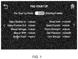
- FIG. 1 is an exemplary graphical user interface (GUI) of a water heater or boiler controller display screen illustrating a new pre-start up procedure;
- GUI graphical user interface
- FIG. 2 is a flowchart showing an exemplary pre-start up procedure according to the Application
- FIG. 3 is a drawing showing an exemplary GUI screen for an auto valve balancing
- FIG. 4 is a drawing showing an exemplary GUI screen for a manual valve balancing
- FIG. 5 shows an exemplary flow chart to perform the new flow balancing method
- FIG. 6 A is a drawing of a programmed auto run GUI to select a sequence of repeating fire rates or setpoints
- FIG. 6 B is a drawing of a programmed auto run GUI to run a programmed auto run profile for a certain number of cycles with a sequence off time between cycles;
- FIG. 6 C is a drawing of a programmed auto run GUI for setting each of the setpoints of FIG. 6 A ;
- FIG. 7 is a flow chart showing the steps of an exemplar programmed auto run mode.
- FIG. 8 is a drawing which shows an exemplary boiler, an AERCO Benchmark boiler having a controller in the front panel;
- FIG. 9 is a drawing showing a heat exchanger, blower, air fuel valve, and gas supply for the exemplary boiler of FIG. 8 ;
- FIG. 10 is a drawing showing the natural gas inlet assembly of FIG. 9 in more detail
- FIG. 11 is a drawing of the exemplary air/fuel valve of FIG. 9 and an associated exemplary valve position
- FIG. 12 is a drawing showing an exemplary flame detector mounted on a flange of the plenum of FIG. 9 ;
- FIG. 13 is a block diagram showing a controller operatively coupled to a display, the air fuel valve, the blower, and the ignitor assembly.
- the description is divided into three parts describing three new processes for water heaters or boilers: a control method—pre-start up, a flow balancing method, and a programmed auto run process.
- a related problem is that utility company personnel called to inspect an installation and/or turn on the gas supply to a new water heater or boiler may be delayed or forced to make a second trip to the site, if when powered, the new water heater or boiler exhibits some fault which delays the inspection and gas turn on process.
- a solution to the problem of commissioning a new water heater or boiler is a new procedure which allows a water heater or boiler technician to check the water heater or boiler unit before the gas is turned ON to the building.
- This new pre-start up procedure ensures that an installer or owner/operator can verify correct operation of the key gas and electric related components before calling for utility company personnel to inspect an installation.
- the utility company person arrives on site, he or she does not have to come back after waiting for some time while an otherwise unexpected or unanticipated problem is fixed.
- FIG. 1 is an exemplary graphical user interface (GUI) of a water heater or boiler controller display screen illustrating a new pre-start up procedure.
- GUI graphical user interface
- FIG. 2 is a flowchart showing an exemplary pre-start up procedure according to the Application.
- the controller A) performs a unit shutdown operation; B) a user can enable the pre-start up mode, such as by making a selection on the pre-start up GUI of FIG. 1 ; C) about at the same time, or in any order, the controller moves an air fuel vale to a non-off position (with the gas supply to the water heater or boiler turned off), the controller turns on a blower at an operational level associated with the set air fuel position, and the controller causes an ignitor to spark.
- Step C can be performed in any suitable order; D) the water heater or boiler controller displays parameters allowing a user to affirm a safe and reliable ignition before the utility company representative arrives to turn ON the gas supply to the water heater or boiler. Step D can occur after each individual operation/test of step C, or at the conclusion of several or all of the steps of step C.
- a plant can include two or more water heaters or boilers which can operate in concert as a “cascade”.
- a boiler sequencing technology an exemplary Boiler Sequencing Technology system (BST) can operate up to 16 boilers as part of an integrated boiler control system.
- BST Boiler Sequencing Technology system
- the Manager When there is a demand, the Manager will light off one of the boilers based on the BST Sequencing selection in the BST Cascade Status screen.
- the Manager will light off one of the boilers based on the BST Sequencing selection in the BST Cascade Status screen. As the systems load, the Manager will light off the next available unit.
- a Valve Balancing screen GUI can be used to setup and configure a Balanced Flow Isolation Valve feature.
- the goal of this Valve Balancing feature is to raise or lower all unit's current ⁇ T (water outlet temp minus water inlet temp) to match the plant's target ⁇ T, thereby balancing the load across multiple boilers (e.g. multiple boilers in a BST cascade).
- ⁇ T water outlet temp minus water inlet temp
- Valve balancing is accomplished by reducing the isolation valve's “fully open” position, thereby restricting the flow from the unit's hot water outlet, as needed, until the unit's ⁇ T matches the plant's target ⁇ T. This can be repeated on the other units in the BST cascade until each unit's ⁇ T is approximately the same.
- a new flow balancing method allows an owner/operator of two or more water heater or boiler units to balance the flow through a valve max position adjustment at a selected valve position and inlet location, while maintaining a given temperature rise.
- the graphical user interface (GUI) screens of the flow balancing method provide a quick visual view of all of the units in a plant, what their temperature rise is, and if they are faulted.
- FIG. 3 is a drawing showing an exemplary GUI screen for an auto valve balancing.
- FIG. 4 is a drawing showing an exemplary GUI screen for a manual valve balancing.
- FIG. 5 shows an exemplary flow chart to perform the new flow balancing method.
- the exemplary method steps include: A) A user (typically and owner or operator), initiates a manual or automatic flow balancing process at a touch screen of one of the units at a plant having two or more hot water heaters or boilers, each with a controller configured for the new method. B) The controller shuts down the plant and sets each unit to a certain fire rate (pre-set, or settable). C) In the automatic mode, the controller automatically each valve position of each unit to achieve a common desired temperature rise (pre-set or settable) across each water heater or boiler unit. Alternatively, in a manual mode, the user adjusts a valve position of each unit manually (from the single controller GUI being used on one controller of one unit) to achieve a common temperature rise across each unit.
- While the controller is performing the functions on the left side of the flowchart, it can simultaneously check that there is no unsafe condition, fault, error, etc. occurring. All the safety checks are in place.
- the block for operational integrity applies the entire time the unit is automatically or manually setting the valve balancing function.
- a solution is a new programmed auto run mode where the owner/operator, or more typically, a repair technician can program a suspect profile to intentionally run on demand
- the new programmed auto run mode an otherwise frustrating seeming random sequence can now be run on demand for the repair technician to observe and diagnose the problem that might repeat only during one or a limited number of sequences or profiles of operation.
- FIG. 6 A to FIG. 6 C shows GUIs associated with an exemplary programmed auto run mode for a boiler controller. These GUIs allows one to troubleshoot the unit via custom profile creation and running the custom profile for a specified duration to trigger a condition that is considered to be random in nature and difficult to debug as a result.
- FIG. 6 A is a drawing of a programmed auto run GUI to select a sequence of repeating fire rates or setpoints. The example screen shows the first three points of a sequence of 13 setpoints and hold times for the set points.
- FIG. 6 B is a drawing of a programmed auto run GUI to run a programmed auto run profile for a certain number of cycles with a sequence off time between cycles.
- FIG. 6 C is a drawing of a programmed auto run GUI for setting each of the setpoints of FIG. 6 A .
- FIG. 7 is a flow chart showing the steps of an exemplar programmed auto run mode.
- FIG. 8 to FIG. 12 illustrate an exemplary Boiler for performing the new methods, such as, for example, including the new pre-startup control method for a boiler or water heater.
- Line voltage (for example, as displayed in FIG. 1 ) is the voltage of the AC building electrical power provided to the boiler system.
- FIG. 8 is a drawing which shows an exemplary boiler, an AERCO Benchmark boiler having a controller in the front panel.
- FIG. 9 is a drawing showing a heat exchanger, blower 920 , air fuel valve 910 , and gas supply 940 for the exemplary boiler of FIG. 8 .
- the blower 920 is driven by the blower motor.
- the voltage applied to the blower motor sets the blower speed.
- Blower voltage and Blower RPM are parameters that are displayed on FIG. 1 .
- Spark current and flame strength are also parameters that are displayed on FIG. 1 of the nonprovisional application as originally filed.
- the Igniter Solenoid opens the gas assist line solenoid and generates sparking of the igniter until the Ignition Spark control is disabled.
- the Spark Current (amps draw from spark across igniter) is displayed.
- FIG. 10 is a drawing showing the natural gas inlet assembly of FIG. 9 in more detail.
- Gas pressure is a parameter that is displayed on FIG. 1 of the nonprovisional application as originally filed.
- the gas supply is off during the pre-start process. Therefore, during the pre-start process, the gas pressure display displays Gas Pressure: “closed”.
- FIG. 11 is a drawing of the exemplary air/fuel valve of FIG. 9 and an associated exemplary valve position.
- Valve position out is a parameter displayed in FIG. 1 .
- the valve position out is the position of the air fuel valve.
- FIG. 12 is a drawing showing an exemplary flame detector 1210 mounted on a flange of the plenum of FIG. 9 .
- Strength mains 0 until the flame sensors senses flame, then displays the flame strength between 0-100%. A flame strength less than 70% can lead to flame loss.
- FIG. 13 is a block diagram showing a controller operatively coupled to a display, the air fuel valve 910 , the blower 920 , the ignitor assembly 930 , and the flame sensor 1210 .
- Controller a controller having disposed within one or more processors
- code in firmware and/or software to provide the features, functions, and modes for a hot water heater or boiler as described hereinabove can be provided on a computer readable non-transitory storage medium.
- a computer readable non-transitory storage medium as non-transitory data storage includes any data stored on any suitable media in a non-fleeting manner
- Such data storage includes any suitable computer readable non-transitory storage medium, including, but not limited to hard drives, non-volatile RAM, SSD devices, CDs, DVDs, etc.
Abstract
Description
Claims (8)
Priority Applications (2)
| Application Number | Priority Date | Filing Date | Title |
|---|---|---|---|
| US16/861,690 US11549681B2 (en) | 2019-05-02 | 2020-04-29 | Water heater and boiler processes |
| US17/989,286 US20230077846A1 (en) | 2019-05-02 | 2022-11-17 | Water heater and boiler processes |
Applications Claiming Priority (2)
| Application Number | Priority Date | Filing Date | Title |
|---|---|---|---|
| US201962842013P | 2019-05-02 | 2019-05-02 | |
| US16/861,690 US11549681B2 (en) | 2019-05-02 | 2020-04-29 | Water heater and boiler processes |
Related Child Applications (1)
| Application Number | Title | Priority Date | Filing Date |
|---|---|---|---|
| US17/989,286 Continuation US20230077846A1 (en) | 2019-05-02 | 2022-11-17 | Water heater and boiler processes |
Publications (2)
| Publication Number | Publication Date |
|---|---|
| US20200348017A1 US20200348017A1 (en) | 2020-11-05 |
| US11549681B2 true US11549681B2 (en) | 2023-01-10 |
Family
ID=73017007
Family Applications (2)
| Application Number | Title | Priority Date | Filing Date |
|---|---|---|---|
| US16/861,690 Active 2040-06-11 US11549681B2 (en) | 2019-05-02 | 2020-04-29 | Water heater and boiler processes |
| US17/989,286 Pending US20230077846A1 (en) | 2019-05-02 | 2022-11-17 | Water heater and boiler processes |
Family Applications After (1)
| Application Number | Title | Priority Date | Filing Date |
|---|---|---|---|
| US17/989,286 Pending US20230077846A1 (en) | 2019-05-02 | 2022-11-17 | Water heater and boiler processes |
Country Status (1)
| Country | Link |
|---|---|
| US (2) | US11549681B2 (en) |
Citations (3)
| Publication number | Priority date | Publication date | Assignee | Title |
|---|---|---|---|---|
| US6059195A (en) * | 1998-01-23 | 2000-05-09 | Tridelta Industries, Inc. | Integrated appliance control system |
| US20120192813A1 (en) * | 2011-01-28 | 2012-08-02 | Aerco International, Inc. | Water heating system |
| US20180356125A1 (en) * | 2012-05-13 | 2018-12-13 | Aerco International, Inc. | Water heating apparatus with parallel heat exchangers |
-
2020
- 2020-04-29 US US16/861,690 patent/US11549681B2/en active Active
-
2022
- 2022-11-17 US US17/989,286 patent/US20230077846A1/en active Pending
Patent Citations (3)
| Publication number | Priority date | Publication date | Assignee | Title |
|---|---|---|---|---|
| US6059195A (en) * | 1998-01-23 | 2000-05-09 | Tridelta Industries, Inc. | Integrated appliance control system |
| US20120192813A1 (en) * | 2011-01-28 | 2012-08-02 | Aerco International, Inc. | Water heating system |
| US20180356125A1 (en) * | 2012-05-13 | 2018-12-13 | Aerco International, Inc. | Water heating apparatus with parallel heat exchangers |
Non-Patent Citations (6)
| Title |
|---|
| Aerco, Natural Gas Modulating and Condensing Hot water Boiler Models, https://d3pcsg2wjq9izr.cloudfront.net/files/77912/download/475366/2.pdf (Year: 2013). * |
| AHRI, Gas Fired Commercial Water Heater, https://www.bockwaterheaters.com/mwdownloads/download/link/id/38/(Year: 2009). * |
| Armstrong, 7 reasons your water heater isn't working,https://armstrongcomfort.com/Blog/7-reasons-your-water-heater-isnt-working (Year: 2018). * |
| Fixya, Fixya, https://www.fixya.com/support/t8447057-am_getting_message (Year: 2011). * |
| Tricity, "Why isn't my gas water heater getting hot?", Jan. 2017, https://www.tricityappliance.com/blog/2017/january/why-isnt-my-gas-water-heater-getting-hot-/ (Year: 2017). * |
| Trinity, Tx-Series IO Manual, https://ntiboilers.com/wp-content/uploads/2018/12/Tx-Series-IO-Manual-2018-07.pdf (Year: 2018). * |
Also Published As
| Publication number | Publication date |
|---|---|
| US20230077846A1 (en) | 2023-03-16 |
| US20200348017A1 (en) | 2020-11-05 |
Similar Documents
| Publication | Publication Date | Title |
|---|---|---|
| US8177544B2 (en) | Selective lockout in a fuel-fired appliance | |
| EP2372247A2 (en) | Combustion controlling device | |
| US10218532B2 (en) | Determination of a state of operation of a domestic appliance | |
| WO2009107897A1 (en) | Safety control apparatus and method for controlling combustion in boiler | |
| CN103868145A (en) | Dry burning prevention control method for wall hanging furnace | |
| KR101562241B1 (en) | An exhaust temperature sensor of the combustion device, Every detection method | |
| US11549681B2 (en) | Water heater and boiler processes | |
| US7664575B2 (en) | Contingency mode operating method for air conditioning system | |
| JP5968356B2 (en) | Connected hot water control device and connected hot water system | |
| US10107521B2 (en) | Connected hot-water supply system | |
| JP5925224B2 (en) | Hot water system | |
| JP6104186B2 (en) | Combustion control device | |
| JP6550832B2 (en) | Combustion device | |
| JP3120009B2 (en) | Combustion control device | |
| TWI647416B (en) | Water heater motor speed correction device and method thereof | |
| JP6989343B2 (en) | Frame rod condition judgment device | |
| KR101617191B1 (en) | Apparatus and Method for controlling alernate current fan at boiler power noise | |
| JPH0617475A (en) | Short-circuit detecting method of control element and open detecting method of load | |
| KR101499543B1 (en) | Method for controlling hot water temperature when detecting breakdown of boiler thermostat | |
| JPH11125463A (en) | Method and system of checking hot-water supplier on malfunctioning | |
| JPH035620A (en) | Combustion controller | |
| CN113606793A (en) | Gas water heating equipment based on alternating current fan and high wind resistance control method thereof | |
| JP2013204897A (en) | Hot water supply system | |
| JP2020038040A (en) | Connected hot water supply system | |
| JP2019074290A (en) | State determination device of uv sensor |
Legal Events
| Date | Code | Title | Description |
|---|---|---|---|
| FEPP | Fee payment procedure |
Free format text: ENTITY STATUS SET TO UNDISCOUNTED (ORIGINAL EVENT CODE: BIG.); ENTITY STATUS OF PATENT OWNER: LARGE ENTITY |
|
| STPP | Information on status: patent application and granting procedure in general |
Free format text: APPLICATION DISPATCHED FROM PREEXAM, NOT YET DOCKETED |
|
| AS | Assignment |
Owner name: AERCO INTERNATIONAL, INC., NEW YORK Free format text: ASSIGNMENT OF ASSIGNORS INTEREST;ASSIGNORS:SHAH, KUNAL;HERNANDEZ, NERY;MCGRATH, SCOTT;AND OTHERS;SIGNING DATES FROM 20190521 TO 20190719;REEL/FRAME:053733/0086 |
|
| STPP | Information on status: patent application and granting procedure in general |
Free format text: DOCKETED NEW CASE - READY FOR EXAMINATION |
|
| STPP | Information on status: patent application and granting procedure in general |
Free format text: NON FINAL ACTION MAILED |
|
| STPP | Information on status: patent application and granting procedure in general |
Free format text: RESPONSE TO NON-FINAL OFFICE ACTION ENTERED AND FORWARDED TO EXAMINER |
|
| STPP | Information on status: patent application and granting procedure in general |
Free format text: FINAL REJECTION MAILED |
|
| STPP | Information on status: patent application and granting procedure in general |
Free format text: RESPONSE AFTER FINAL ACTION FORWARDED TO EXAMINER |
|
| STPP | Information on status: patent application and granting procedure in general |
Free format text: DOCKETED NEW CASE - READY FOR EXAMINATION |
|
| STPP | Information on status: patent application and granting procedure in general |
Free format text: NOTICE OF ALLOWANCE MAILED -- APPLICATION RECEIVED IN OFFICE OF PUBLICATIONS |
|
| STPP | Information on status: patent application and granting procedure in general |
Free format text: PUBLICATIONS -- ISSUE FEE PAYMENT VERIFIED |
|
| STCF | Information on status: patent grant |
Free format text: PATENTED CASE |