US11528858B2 - Plant cultivating apparatus - Google Patents
Plant cultivating apparatus Download PDFInfo
- Publication number
- US11528858B2 US11528858B2 US16/685,801 US201916685801A US11528858B2 US 11528858 B2 US11528858 B2 US 11528858B2 US 201916685801 A US201916685801 A US 201916685801A US 11528858 B2 US11528858 B2 US 11528858B2
- Authority
- US
- United States
- Prior art keywords
- bed
- level
- cultivation bed
- nutrient solution
- checker
- Prior art date
- Legal status (The legal status is an assumption and is not a legal conclusion. Google has not performed a legal analysis and makes no representation as to the accuracy of the status listed.)
- Active, expires
Links
- 235000015097 nutrients Nutrition 0.000 claims abstract description 132
- NJPPVKZQTLUDBO-UHFFFAOYSA-N novaluron Chemical compound C1=C(Cl)C(OC(F)(F)C(OC(F)(F)F)F)=CC=C1NC(=O)NC(=O)C1=C(F)C=CC=C1F NJPPVKZQTLUDBO-UHFFFAOYSA-N 0.000 claims description 23
- XLYOFNOQVPJJNP-UHFFFAOYSA-N water Substances O XLYOFNOQVPJJNP-UHFFFAOYSA-N 0.000 description 11
- 238000009423 ventilation Methods 0.000 description 8
- 238000011084 recovery Methods 0.000 description 4
- 238000001816 cooling Methods 0.000 description 3
- CURLTUGMZLYLDI-UHFFFAOYSA-N Carbon dioxide Chemical compound O=C=O CURLTUGMZLYLDI-UHFFFAOYSA-N 0.000 description 2
- 230000005540 biological transmission Effects 0.000 description 2
- 239000004020 conductor Substances 0.000 description 2
- 239000011521 glass Substances 0.000 description 2
- 230000008635 plant growth Effects 0.000 description 2
- 238000000926 separation method Methods 0.000 description 2
- 238000007664 blowing Methods 0.000 description 1
- 229910002092 carbon dioxide Inorganic materials 0.000 description 1
- 239000001569 carbon dioxide Substances 0.000 description 1
- 238000005516 engineering process Methods 0.000 description 1
- 230000012010 growth Effects 0.000 description 1
- 238000004519 manufacturing process Methods 0.000 description 1
- 238000009331 sowing Methods 0.000 description 1
Images


Classifications
-
- A—HUMAN NECESSITIES
- A01—AGRICULTURE; FORESTRY; ANIMAL HUSBANDRY; HUNTING; TRAPPING; FISHING
- A01G—HORTICULTURE; CULTIVATION OF VEGETABLES, FLOWERS, RICE, FRUIT, VINES, HOPS OR SEAWEED; FORESTRY; WATERING
- A01G9/00—Cultivation in receptacles, forcing-frames or greenhouses; Edging for beds, lawn or the like
- A01G9/24—Devices or systems for heating, ventilating, regulating temperature, illuminating, or watering, in greenhouses, forcing-frames, or the like
-
- A—HUMAN NECESSITIES
- A01—AGRICULTURE; FORESTRY; ANIMAL HUSBANDRY; HUNTING; TRAPPING; FISHING
- A01G—HORTICULTURE; CULTIVATION OF VEGETABLES, FLOWERS, RICE, FRUIT, VINES, HOPS OR SEAWEED; FORESTRY; WATERING
- A01G31/00—Soilless cultivation, e.g. hydroponics
- A01G31/02—Special apparatus therefor
- A01G31/06—Hydroponic culture on racks or in stacked containers
-
- A—HUMAN NECESSITIES
- A01—AGRICULTURE; FORESTRY; ANIMAL HUSBANDRY; HUNTING; TRAPPING; FISHING
- A01G—HORTICULTURE; CULTIVATION OF VEGETABLES, FLOWERS, RICE, FRUIT, VINES, HOPS OR SEAWEED; FORESTRY; WATERING
- A01G31/00—Soilless cultivation, e.g. hydroponics
- A01G31/02—Special apparatus therefor
-
- A—HUMAN NECESSITIES
- A01—AGRICULTURE; FORESTRY; ANIMAL HUSBANDRY; HUNTING; TRAPPING; FISHING
- A01G—HORTICULTURE; CULTIVATION OF VEGETABLES, FLOWERS, RICE, FRUIT, VINES, HOPS OR SEAWEED; FORESTRY; WATERING
- A01G27/00—Self-acting watering devices, e.g. for flower-pots
- A01G27/003—Control of self-acting watering devices
-
- A—HUMAN NECESSITIES
- A01—AGRICULTURE; FORESTRY; ANIMAL HUSBANDRY; HUNTING; TRAPPING; FISHING
- A01G—HORTICULTURE; CULTIVATION OF VEGETABLES, FLOWERS, RICE, FRUIT, VINES, HOPS OR SEAWEED; FORESTRY; WATERING
- A01G27/00—Self-acting watering devices, e.g. for flower-pots
- A01G27/008—Component parts, e.g. dispensing fittings, level indicators
-
- A—HUMAN NECESSITIES
- A01—AGRICULTURE; FORESTRY; ANIMAL HUSBANDRY; HUNTING; TRAPPING; FISHING
- A01G—HORTICULTURE; CULTIVATION OF VEGETABLES, FLOWERS, RICE, FRUIT, VINES, HOPS OR SEAWEED; FORESTRY; WATERING
- A01G31/00—Soilless cultivation, e.g. hydroponics
- A01G31/02—Special apparatus therefor
- A01G31/065—Special apparatus therefor with means for recycling the nutritive solution
-
- A—HUMAN NECESSITIES
- A01—AGRICULTURE; FORESTRY; ANIMAL HUSBANDRY; HUNTING; TRAPPING; FISHING
- A01G—HORTICULTURE; CULTIVATION OF VEGETABLES, FLOWERS, RICE, FRUIT, VINES, HOPS OR SEAWEED; FORESTRY; WATERING
- A01G7/00—Botany in general
- A01G7/04—Electric or magnetic or acoustic treatment of plants for promoting growth
- A01G7/045—Electric or magnetic or acoustic treatment of plants for promoting growth with electric lighting
-
- G—PHYSICS
- G05—CONTROLLING; REGULATING
- G05D—SYSTEMS FOR CONTROLLING OR REGULATING NON-ELECTRIC VARIABLES
- G05D9/00—Level control, e.g. controlling quantity of material stored in vessel
- G05D9/12—Level control, e.g. controlling quantity of material stored in vessel characterised by the use of electric means
-
- Y—GENERAL TAGGING OF NEW TECHNOLOGICAL DEVELOPMENTS; GENERAL TAGGING OF CROSS-SECTIONAL TECHNOLOGIES SPANNING OVER SEVERAL SECTIONS OF THE IPC; TECHNICAL SUBJECTS COVERED BY FORMER USPC CROSS-REFERENCE ART COLLECTIONS [XRACs] AND DIGESTS
- Y02—TECHNOLOGIES OR APPLICATIONS FOR MITIGATION OR ADAPTATION AGAINST CLIMATE CHANGE
- Y02A—TECHNOLOGIES FOR ADAPTATION TO CLIMATE CHANGE
- Y02A40/00—Adaptation technologies in agriculture, forestry, livestock or agroalimentary production
- Y02A40/10—Adaptation technologies in agriculture, forestry, livestock or agroalimentary production in agriculture
- Y02A40/25—Greenhouse technology, e.g. cooling systems therefor
-
- Y—GENERAL TAGGING OF NEW TECHNOLOGICAL DEVELOPMENTS; GENERAL TAGGING OF CROSS-SECTIONAL TECHNOLOGIES SPANNING OVER SEVERAL SECTIONS OF THE IPC; TECHNICAL SUBJECTS COVERED BY FORMER USPC CROSS-REFERENCE ART COLLECTIONS [XRACs] AND DIGESTS
- Y02—TECHNOLOGIES OR APPLICATIONS FOR MITIGATION OR ADAPTATION AGAINST CLIMATE CHANGE
- Y02P—CLIMATE CHANGE MITIGATION TECHNOLOGIES IN THE PRODUCTION OR PROCESSING OF GOODS
- Y02P60/00—Technologies relating to agriculture, livestock or agroalimentary industries
- Y02P60/20—Reduction of greenhouse gas [GHG] emissions in agriculture, e.g. CO2
- Y02P60/21—Dinitrogen oxide [N2O], e.g. using aquaponics, hydroponics or efficiency measures
Definitions
- the present disclosure relates to a plant cultivating apparatus.
- the general plant cultivating apparatus forms a preset cultivation chamber having an environment suitable for plant growth, and stores plant in the preset cultivation chamber.
- the plant cultivating apparatus is provided with a configuration for supplying nutrients and light energy necessary for plant growth, and the plant is grown by the nutrients and light energy supplied.
- Korean Patent No. 10-1240375 a technology related to “Plant Cultivating apparatus” is disclosed.
- the nutrient solution supplied to the cultivation bed flows out to a recovery pipe having a constant height, and a constant water level is maintained by the recovery pipe.
- the nutrient solution overflows from the cultivation bed if the supply amount of the nutrient solution is larger than the outflow amount flowing into the recovery pipe.
- the light energy supplied to the plant is reduced if the cultivation bed movably provided in the plant cultivating apparatus is disposed in the wrong position.
- the nutrient solution is not properly supplied to the cultivation bed if the cultivation bed movably provided in the plant cultivating apparatus is disposed in the wrong position.
- An object of the present disclosure is to provide a plant cultivating apparatus that can easily grasp the level of the nutrient solution supplied to the cultivation bed.
- An object of the present disclosure is to provide a plant cultivating apparatus that can easily grasp whether a cultivation bed movably provided is disposed at an exact position.
- the plant cultivating apparatus may include a bed check unit for detecting the movement of the cultivation bed movably provided relative to the body, and the bed check unit can detect the movement of the cultivation bed according to whether the cultivation bed is moved relative to the body.
- the plant cultivating apparatus includes a level check unit for detecting the level of nutrient solution stored in the cultivation bed and can adjust whether the nutrient solution is supplied to the cultivation bed according to the level of the nutrient solution stored in the cultivation bed.
- the plant cultivating apparatus may adjust whether the nutrient solution is supplied to the cultivation bed by adjusting whether to detect the level of the nutrient solution stored in the cultivation bed according to whether to the movement of the cultivation bed detected by the bed check unit.
- whether the supply of nutrient solution supplied to the cultivation bed is adjusted according to whether to the movement of the cultivation bed, thereby preventing a leak that may occur if the nutrient solution is supplied to the cultivation bed.
- light energy can be uniformly supplied to plants sown in the cultivation bed in order to detect whether to detect movement of the cultivation bed.
- the signal for detecting the level of the nutrient solution is immediately changed according to the level of the nutrient solution supplied to the cultivation bed, it is possible to adjust whether to supply the nutrient solution by quickly and accurately grasping the level.
- the present disclosure by simplifying the configuration for detecting the movement of the cultivation bed and the configuration for detecting the level of nutrient solution stored in the cultivation bed, it is possible to reduce the manufacturing cost of the plant cultivating apparatus.
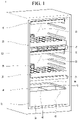
- FIG. 1 is a perspective view illustrating a plant cultivating apparatus according to the present disclosure.
- FIG. 2 is a view illustrating a state where the cultivation bed of the plant cultivating apparatus according to the invention is drawn into.
- FIG. 3 is a view illustrating a state where the cultivation bed of the plant cultivating apparatus according to the present disclosure is drawn out.
- FIG. 4 is a view illustrating a state where the nutrient solution is supplied to the cultivation bed of the plant cultivating apparatus according to the present disclosure.
- FIG. 5 is a view illustrating a state whether the nutrient solution supplied to the cultivation bed of the plant cultivating apparatus according to the present disclosure is blocked.
- first, second, A, B, (a), and (b) may be used. These terms are only for distinguishing the components from other components, and the nature, sequence, or order of the components are not limited by the terms. If a component is described as being “connected”, “coupled” or “accessed” to another component, that component may be directly connected or accessed to that other component, but It is to be understood that another component may be “connected”, “coupled” or “accessed” between each component.
- FIG. 1 is a perspective view illustrating a plant cultivating apparatus according to the present disclosure.
- the plant cultivating apparatus 1 may include a body 10 .
- the body 10 may be formed so that one side thereof is opened.
- An inner space may be formed in the body 10 .
- the door 15 may be disposed at an opened side of the body 10 .
- the door 15 may selectively shield one opened side of the body 10 .
- the door 15 and the body 10 may be connected by a hinge.
- the door 15 may be provided with a front glass 16 .
- the inner space of the body 10 may be exposed to the outside by the front glass 16 .
- the plant cultivating apparatus 1 may include a cultivation bed 20 .
- the cultivation bed 20 may be disposed in an inner space of the body 10 . Plants may grow in the cultivation bed 20 .
- the cultivation bed 20 may support the growing plant and supply nutrients to the plant.
- the cultivation bed 20 may be configured to store the nutrient solution containing the nutrients required for the growth of the plant.
- the cultivation bed 20 may include a bed body formed in a polygon in which one surface is opened. A storage space for storing nutrient solution may be formed in the bed body. The storage space may be defined by the inner surface of the bed body.
- the cultivation bed 20 may further include a bed cover which covers an opened surface of the bed body. The bed cover may be detachably mounted to the bed body.
- the bed cover may be provided with a plurality of holes in which a plurality of plants can be disposed.
- a plurality of cultivation beds 20 may be provided.
- the plurality of cultivation beds 20 may be disposed so as to be spaced apart from each other in the vertical direction in the body 10 .
- a bed pedestal 25 for supporting the cultivation bed 20 may be provided in the body 10 .
- the bed pedestal 25 may be configured to be movable relative to the body 10 .
- the bed pedestal 25 may be fixed to the body 10 . If the bed pedestal 25 is configured to be movable relative to the body 10 , the cultivation bed 20 may be moved by the bed pedestal 25 . If the bed pedestal 25 is fixed to the body 10 , the cultivation bed 20 may slide in the bed pedestal 25 .
- the plant cultivating apparatus 1 may include a light source module 30 .
- the light source module 30 may be disposed in the body 10 .
- the light source module 30 may be disposed above the cultivation bed 20 .
- the light source module 30 may supply light energy to a plant growing in the cultivation bed 20 .
- the light source module 30 may include a light source for generating light, a power supply unit supplying power to the light source, a reflecting plate reflecting light, and the like.
- the light source module 30 may further include a cooling unit for cooling the light source. The cooling unit may cool the heat generated by the light source to improve the life of the light source.
- a cultivation chamber 11 may be defined between the cultivation bed 20 and the light source module 30 .
- the cultivation chamber 11 can be understood as a space in which plants sown in the cultivation bed 20 can grow.
- the ventilation unit 35 may be provided in the body 10 .
- the ventilation unit 35 may supply outside air to the inside of the cultivation chamber 11 .
- the ventilation unit 35 may be provided as a blowing fan.
- the ventilation unit 35 may selectively communicate the cultivation chamber 11 and external space with each other.
- the ventilation unit 35 may supply outside air into the cultivation chamber 11 to control moisture, carbon dioxide concentration, and the like in the cultivation chamber 11 .
- the plant cultivating apparatus 1 may include a nutrient solution storage unit 40 .
- the nutrient solution storage unit 40 may be disposed in the body 10 .
- the nutrient solution may be stored in the nutrient solution storage unit 40 .
- the nutrient solution storage unit 40 may be disposed below the body 10 .
- the nutrient solution storage unit 40 may include a hot water tank 41 , a cold water tank 42 , and a separation plate 43 .
- the warm nutrient solution may be stored in the hot water tank 41
- the cold nutrient solution may be stored in the cold water tank 42 .
- the hot water tank 41 and the cold water tank 42 may be divided by the separation plate 43 .
- Nutrient solution stored in each of the hot water tank 41 and the cold water tank 42 may be supplied to the cultivation bed 20 .
- the nutrient solutions of different temperatures from each other stored in the hot water tank 41 and the cold water tank 42 may be mixed and supplied to the cultivation bed 20 .
- the temperature of the nutrient solution present in the cultivation bed 20 may be measured, and a nutrient solution of a preset temperature based on the measured temperature may be supplied.
- the plant cultivating apparatus 1 may include a nutrient solution pump 44 .
- the nutrient solution pump 44 may be disposed at one side of the nutrient solution storage unit 40 .
- the nutrient solution stored in the nutrient solution storage unit 40 may be supplied to the cultivation bed 20 by the nutrient solution pump 44 .
- the nutrient solution pump 44 and the nutrient solution storage unit 40 may be connected by a pipe 45 .
- the nutrient solution pump 44 and the cultivation bed 20 may be connected by a pipe 45 .
- the nutrient solution stored in the nutrient storage unit 40 may be supplied to the cultivation bed 20 through the pipe 45 .
- the pipe for supplying the nutrient solution from the nutrient solution storage unit 40 to the cultivation bed 20 may be referred to as a supply pipe.
- the pipe 45 can be disposed above the cultivation bed 20 to prevent from being in contact with the cultivation bed 20 if the cultivation bed 20 moves in the front and rear direction.
- the pipe 45 may further include a valve. The valve may be controlled by the control unit 100 to be described later.
- the cultivation bed 20 and the nutrient solution storage unit 40 are connected by a pipe 45 , and thus the nutrient solution stored in the cultivation bed 20 may be recovered to the nutrient solution storage unit 40 .
- the pipe 45 connecting the cultivation bed 20 and the nutrient solution storage unit 40 may be referred to as a recovery pipe.
- FIG. 2 is a view illustrating a state where the cultivation bed of the plant cultivating apparatus according to the invention is drawn into
- FIG. 3 is a view illustrating a state where the cultivation bed of the plant cultivating apparatus according to the present disclosure is drawn out.
- the plant cultivating apparatus 1 may include a control unit 100 .
- the control unit 100 may control the operation of the plant cultivating apparatus 1 .
- the control unit 100 may control the operation of the ventilation unit 35 to improve the environment of the cultivation chamber 11 .
- the control unit 100 may control the operation of the light source module 30 to adjust the amount of light irradiated to the plant growing in the cultivation chamber 11 or may turn on/off the light source.
- the control unit 100 may control the operation of the nutrient solution pump 44 to adjust the supply amount of nutrient solution supplied to the cultivation bed 20 .
- the control unit 100 may include a configuration for informing the user of the operating state of the plant cultivating apparatus 1 .
- control unit 100 may determine whether the cultivation bed 20 is drawn into and out, and adjust whether the nutrient solution supplied to the cultivation bed 20 is supplied. In addition, in the present embodiment, the control unit 100 may adjust the supply amount of the nutrient solution supplied to the cultivation bed 20 .
- the control unit 100 may include a bed check unit 110 .
- the bed check unit 110 may grasp whether the cultivation bed 20 is mounted on the body 10 of the plant cultivating apparatus 1 .
- the cultivation bed 20 may move with respect to the body 10 in the rear and front direction. At this time, if the cultivation bed 20 is moved to the front, the cultivation bed 20 may be drawn out to the outer space. If the cultivation bed 20 is moved to the rear, the cultivation bed 20 may be drawn into the inner space of the body 10 .
- the bed check unit 110 may grasp whether the cultivation bed 20 is drawn into the inner space of the body 10 .
- the bed check unit 110 can grasp whether a portion of the cultivation bed 20 is in contact with one surface of the body 10 in a state where the cultivation bed 20 is seated on the bed pedestal 25 .
- one surface of the body 10 can be understood as an inner surface of the body 10 forming the cultivation chamber 11 .
- the bed check unit 110 may include a first signal output unit 111 and a first signal input unit 112 .
- the bed check unit 110 may be provided in the body 10 of the plant cultivating apparatus 1 .
- the first signal output unit 111 and the first signal input unit 112 may be connected to the control unit 100 .
- the first signal output unit 111 and the first signal input unit 112 may be provided to transmit electrical signals by terminals, conductors, cables, electric wires, or the like.
- One end of the first signal output unit 111 and one end of the first signal input unit 112 may be connected to the control unit 100 .
- the other end of the first signal output unit 111 and the other end of the first signal input unit 112 may be exposed to the inner surface of the body 10 .
- An extension portion connecting one end and the other end of the first signal output unit 111 and an extension portion connecting one end and the other end of the first signal input unit 112 may be disposed in the body 10 .
- the first signal output unit 111 and the first signal input unit 112 may be spaced apart from each other.
- the first signal output unit 111 may be defined as a transmission end for receiving an electrical signal from the control unit 100 and transmitting the electrical signal to the first signal input unit 112 or a signal output end for outputting an electrical signal.
- the first signal input unit 112 may be defined as a reception end for receiving an electrical signal from the first signal output unit 111 and transmitting the electrical signal to the control unit 100 or a signal input end for receiving an electrical signal.
- the control unit 100 , the first signal output unit 111 , and the first signal input unit 112 may be connected to each other by a first signal connection unit 131 , which will be described later, to form a closed curve for transmitting an electrical signal.
- An electrical signal transmitted from the first signal output unit 111 and the first signal input unit 112 may be defined as a first signal.
- the first signal may include information that the cultivation bed 20 is drawn out or into.
- the control unit 100 may include a level check unit 120 .
- the level check unit 120 may determine the level of the nutrient solution stored in the cultivation bed 20 .
- the level check unit 120 may grasp the level of the nutrient solution stored in the cultivation bed 20 in a state where the cultivation bed 20 is seated on the bed pedestal 25 .
- the level check unit 120 may operate in conjunction with the bed check unit 110 .
- the level check unit 120 may recognize whether the cultivation bed 20 is mounted from the bed check unit 110 and grasp the level of the nutrient solution stored in the cultivation bed 20 .
- the level check unit 120 may measure the level of the nutrient solution stored in the cultivation bed 20 while the cultivation bed 20 is mounted on the bed pedestal 25 .
- the level check unit 120 may include a second signal output unit 121 and a second signal input unit 122 .
- the level check unit 120 may be provided in the body 10 of the plant cultivating apparatus 1 .
- the second signal output unit 121 and the second signal input unit 122 may be connected to the control unit 100 .
- the second signal output unit 121 and the second signal input unit 122 may be provided to transmit electrical signals by terminals, conductors, cables, wires, or the like.
- One end of the second signal output unit 121 and one end of the second signal input unit 122 may be connected to the control unit 100 .
- the other end of the second signal output unit 121 and the other end of the second signal input unit 122 may be exposed to the inner surface of the body 10 .
- An extension portion connecting one end and the other end of the second signal output unit 121 and an extension portion connecting one end and the other end of the second signal input unit 122 may be disposed in the body 10 .
- the second signal output unit 121 and the second signal input unit 122 may be spaced apart from each other.
- the level check unit 120 may be disposed below the bed check unit 110 .
- the level check unit 120 may be disposed below the bed check unit 110 to install a second level check end 134 for checking the low level of the nutrient solution.
- the bed check unit 110 and the level check unit 120 may be disposed to be spaced apart from each other to minimize electrical interference.
- the second signal output unit 121 may be defined as a transmission end for receiving an electrical signal from the control unit 100 and transmitting the electrical signal to the second signal input unit 122 or a signal output end for outputting an electrical signal.
- the second signal input unit 122 may be defined as a reception end for receiving an electrical signal from the second signal output unit 121 and transmitting the electrical signal to the control unit 100 or a signal input end for receiving an electrical signal.
- the control unit 100 , the second signal output unit 121 , and the second signal input unit 122 may be connected to a first level check end 132 , a second level check end 134 , and a second signal connection unit 133 which are described later.
- the first level check end 132 and the second level check end 134 may be energized with each other by the nutrient solution W stored in the cultivation bed 20 .
- the first level check end 132 and the second level check end 134 may determine whether or not to energize according to the level of the nutrient solution W stored in the cultivation bed 20 .
- the level check unit 120 can grasp the level of the nutrient solution W according to whether the first level check end 132 and the second level check end 134 are energized with each other by the nutrient solution W.
- An electrical signal transmitted from the second signal output unit 121 and the second signal input unit 122 may be defined as a second signal.
- the second signal may include information for grasping the level of nutrient solution stored in the cultivation bed 20 .
- the plant cultivating apparatus 1 may include a signal connection unit 130 .
- the signal connection unit 130 may be provided to the cultivation bed 20 .
- a portion of the signal connection unit 130 may be disposed in the cultivation bed 20 .
- the remaining portion of the signal connection unit 130 may be exposed to the outer surface of the cultivation bed 20 .
- the signal connection unit 130 may connect the first signal output unit 111 and the first signal input unit 112 or may connect the second signal output unit 121 and the second signal input unit 122 .
- the signal connection unit 130 may include a first signal connection unit 131 .
- the first signal connection unit 131 may connect the first signal output unit 111 and the first signal input unit 112 of the bed check unit 110 .
- the first signal connection unit 131 may be disposed on the rear surface of the cultivation bed 20 .
- the rear surface of the cultivation bed 20 may be understood as one surface of the bed body facing the inner surface of the body 10 if the cultivation bed 20 is drawn into the body 10 .
- a portion of the first signal connection unit 131 may be disposed in the cultivation bed 20 , and the remaining portion of the first signal connection unit 131 may be exposed in a direction toward the inner surface of the body 10 .
- One end of the first signal connection unit 131 may be disposed at a position corresponding to the other end of the first signal output unit 111 .
- One end of the first signal connection unit 131 may be exposed to the outer surface of the cultivation bed 20 .
- One end of the first signal connection unit 131 may be exposed in a direction toward the inner surface of the body 10 to be in contact with the first signal output unit 111 .
- the other end of the first signal connection unit 131 may be disposed at a position corresponding to the other end of the first signal input unit 112 .
- the other end of the first signal connection unit 131 may be exposed to the outer surface of the cultivation bed 20 .
- the other end of the first signal connection unit 131 may be exposed in a direction toward the inner surface of the body 10 to be in contact with the first signal input unit 112 .
- An extension portion connecting one end and the other end of the first signal connection unit 131 may be disposed in the rear surface of the cultivation bed 20 .
- an extension portion connecting one end and the other end of the first signal connection unit 131 may be disposed on an outer surface of the cultivation bed 20 .
- the first signal output unit 111 and the first signal input unit 112 may be connected to each other by the first signal connection unit 131 .
- the control unit 100 can grasp whether the electrical signal transmitted by the first signal output unit 111 , the first signal input unit 112 , and the first signal connection unit 131 is transmitted and can grasp whether the cultivation bed 20 is drawn into or out. In the present embodiment, if an electrical signal is transmitted by the first signal output unit 111 , the first signal input unit 112 , and the first signal connection unit 131 , the control unit 100 can recognize that the cultivation bed 20 is mounted at the exact position.
- the signal connection unit 130 may include a plurality of level check ends 132 and 134 .
- the level check ends 132 and 134 may include a first level check end 132 and a second level check end 134 .
- the first level check end 132 and the second level check end 134 may be provided to the cultivation bed 20 .
- the first level check end 132 and the second level check end 134 may be spaced apart from each other in the vertical direction.
- the first level check end 132 may be disposed above the second level check end 134 .
- the first level check end 132 may be disposed above the storage space in which the nutrient solution W is stored in the cultivation bed 20 .
- the second level check end 134 may be disposed below the storage space in which the nutrient solution W is stored in the cultivation bed 20 .
- the first level check end 132 may be disposed on one side surface of the cultivation bed 20 .
- the second level check end 134 may be disposed on the other side surface of the cultivation bed 20 .
- a portion of the first level check end 132 may be exposed to the inner surface of the cultivation bed 20 .
- a portion of the second level check end 134 may be exposed to the inner surface of the cultivation bed 20 and the outer surface of the cultivation bed 20 .
- one end of the first level check end 132 and one end of the second level check end 134 may be exposed to the inner surface of the cultivation bed 20 .
- the other end of the second level check end 134 may be exposed to the outer surface of the cultivation bed 20 .
- the other end of the second level check end 134 may be disposed at a position corresponding to the second signal input unit 122 . If the cultivation bed 20 is mounted in the body 10 , the other end of the second level check end 134 and the other end of the second signal input unit 122 may be in contact with each other.
- the remaining portion of the first level check end 132 may be disposed in one surface of the cultivation bed 20 .
- the remaining portion of the second level check end 134 may be disposed in the rear surface of the cultivation bed 20 .
- an extension portion extending from one end of the first level check end 132 may be disposed in one side surface of the cultivation bed 20 .
- the extension portion extending from the first level check end 132 may be connected to the second signal connection unit 133 which will be described later.
- An extension portion connecting one end and the other end of the second level check end 134 may be disposed in the other side surface of the cultivation bed 20 .
- One end of the first level check end 132 and one end of the second level check end 134 may be in contact with the nutrient solution W according to the level of the nutrient solution W stored in the cultivation bed 20 .
- the first level check end 132 and the second level check end 134 may be energized with each other by the nutrient solution W.
- the electrical signal transmitted to the first level check end 132 may be transmitted to the second level check end 134 after passing through the nutrient solution W.
- the control unit 100 can grasp whether the electrical signal transmitted by the first level check end 132 , the second level check end 134 , and the nutrient solution W is transmitted and can grasp the level of the nutrient solution W stored in the cultivation bed.
- the control unit can adjust a height at which the nutrient solution W is stored by adjusting a distance formed by the first level check end 132 and the second level check end 134 being spaced apart from each other.
- the height at which the nutrient solution W is stored may be a height at which the nutrient solution W may be in contact with the root of a plant sown in the cultivation bed 20 .
- the first level check end 132 can be disposed at a first height H 1 which prevents the nutrient solution W from being excessively supplied and to which the nutrient solution W may be in contact with the root of the plant sown.
- the second level check end 134 may not be in contact with the nutrient solution to the root of the plant sown and may be disposed at a second height H 2 adjacent to the bottom surface of the storage space in which the nutrient solution W is stored.
- the first height H 1 and the second height H 2 may be defined as heights spaced upwardly from a bottom of a storage space in which the nutrient solution W is stored.
- the first height H 1 may be disposed to be higher than the second height H 2 .
- the second height H 2 may be defined as a low level, and the first height H 2 may be defined as a high level.
- the signal connection unit 130 may include a second signal connection unit 133 .
- the second signal connecting unit 133 may connect the first level check end 132 and the second signal output unit 121 .
- One end of the second signal connection unit 133 may be exposed to the outer surface of the cultivation bed 20 .
- One end of the second signal connection unit 133 may be disposed at a position corresponding to the second signal output unit 121 .
- One end of the second signal connection unit 133 may be exposed in a direction toward the inner surface of the body 10 .
- One end of the second signal connection unit 133 may be exposed in a direction toward the inner surface of the body 10 to be in contact with the second signal output unit 121 .
- the other end of the second signal connection unit 133 may be connected to an extension portion extending from one end of the first level check end 132 .
- An extension portion connecting one end and the other end of the second signal connection unit 133 may be disposed inside one or more of a bottom surface and a plurality of side surfaces of the cultivation bed 20 .
- the second signal connection unit 133 may be disposed on one side surface of the cultivation bed 20 in which the first level check end 132 is disposed and in the bottom surface of the cultivation bed 20 .
- the second signal output unit 121 may be connected to the first level check terminal 132 by the signal connection unit 130 .
- the second signal input unit 122 may be connected to the second level check end 134 .
- the control unit 100 may grasp the level of the nutrient solution W stored in the cultivation bed 20 if the level check unit 120 and the signal connection unit 130 are connected to each other. The control unit 100 may adjust the amount of nutrient solution W supplied to the cultivation bed 20 through the pipe 45 according to the level of the nutrient solution W stored in the cultivation bed 20 .
- the bed check unit 110 and the level check unit 120 may be disposed on at least one surface of the inner surface of the body 10 forming one surface of the cultivation chamber 11 .
- the signal connection unit 130 may be disposed at a position corresponding to the bed check unit 110 and the level check unit 120 .
- the signal connection unit 130 may be disposed on the side surface of a cultivation bed 20 corresponding to the side surface.
- FIG. 4 is a view illustrating a state where the nutrient solution is supplied to the cultivation bed of the plant cultivating apparatus according to the present disclosure
- FIG. 5 is a view illustrating a state whether the nutrient solution supplied to the cultivation bed of the plant cultivating apparatus according to the present disclosure is blocked.
- the user in a state where the cultivation bed 20 is drawn out of the body 10 , the user may sow the plant or check the state of the plant. After sowing of the plant or managing the plant, the user may draw the cultivation bed 20 into the body 10 .
- the cultivation bed 20 may be slidably moved in a state of being seated on the bed pedestal 25 to be drawn into the body 10 .
- the bed check unit 110 may grasp whether the cultivation bed 20 is drawn into the exact position. In detail, if the cultivation bed 20 is drawn into the body 10 , the rear surface of the cultivation bed 20 may be moved in a direction toward the inner surface of the body 10 .
- the bed check unit 110 may grasp whether the rear surface of the cultivation bed 20 is in contact with the inner surface of the body 10 . If the cultivation bed 20 is in contact with the inner surface of the body 10 , the first signal connection unit 131 disposed in the rear surface of the cultivation bed 20 may be connected to the first signal output unit 111 and the first signal input unit 112 of the bed check unit 110 . If the first signal connection unit 131 , the first signal output unit 111 , and the first signal input unit 112 are connected, the control unit 100 can recognize that the cultivation bed 20 has reached the exact position in the body 10 . If the cultivation bed 20 is correctly drawn into the body 10 , the control unit 100 may check the level of the cultivation bed 20 using the level check unit 120 .
- the second signal output unit 121 and the second signal input unit 122 of the level check unit 120 may be connected to a first level check end 132 , a second level check end 134 , and the second signal connection unit 133 of the cultivation bed 20 .
- the first level check end 132 and the second level check end 134 may be disposed to be spaced apart from each other in the vertical direction to grasp the level of the nutrient solution W stored in the cultivation bed 20 .
- the control unit 100 may grasp whether the first level check end 132 and the second level check end 134 are immersed in the nutrient solution W stored in the cultivation bed 20 and grasp the level of the nutrient solution.
- the first nutrient solution W 1 stored in the cultivation bed 20 may be in contact with the second level check end 134 , but may not be in contact with the first level check end 132 .
- the control unit 100 recognizes that the level of the first nutrient solution W 1 stored in the cultivation bed 20 is insufficient, and operates the nutrient solution pump 44 to supply the nutrient solution.
- the cultivation bed 20 may be drawn out of the body 10 while the first nutrient solution W 1 is supplied to the cultivation bed 20 . If the cultivation bed 20 is drawn out to the outside of the body 10 , the bed check unit 110 can be detected that the cultivation bed 20 is drawn out from the inner portion of the body 10 to the outer portion of the body 10 . If it is detected that the cultivation bed 20 is drawn out from the body 10 , the control unit 100 may stop the operation of the nutrient solution pump 44 , so that the nutrient solution is not supplied.
- the second nutrient solution W 2 stored in the cultivation bed 20 may be in contact with the first level check end 132 and the second level check end 134 . If the first level check end 132 and the second level check end 134 are immersed in the second nutrient solution W 2 , the control unit 100 may recognize that the level of the second nutrient solution W 2 stored in the cultivation bed 20 has reached the set height, and thus the operation of the nutrient solution pump 44 can be stopped not to supply the nutrient solution.
Landscapes
- Life Sciences & Earth Sciences (AREA)
- Environmental Sciences (AREA)
- Engineering & Computer Science (AREA)
- Water Supply & Treatment (AREA)
- Biodiversity & Conservation Biology (AREA)
- Botany (AREA)
- Ecology (AREA)
- Forests & Forestry (AREA)
- Physics & Mathematics (AREA)
- General Physics & Mathematics (AREA)
- Automation & Control Theory (AREA)
- Hydroponics (AREA)
Abstract
Description
| EXPLANATION OF REFERENCE NUMERAL |
| 1: plant cultivating apparatus | 10: body | ||
| 11: cultivation chamber | 20: cultivation bed | ||
| 25: bed support unit | 30: light source module | ||
| 35: ventilation unit | 40: nutrient solution storage unit | ||
Claims (17)
Applications Claiming Priority (2)
| Application Number | Priority Date | Filing Date | Title |
|---|---|---|---|
| KR1020180140898A KR102719661B1 (en) | 2018-11-15 | 2018-11-15 | Plant cultivating apparatus |
| KR10-2018-0140898 | 2018-11-15 |
Publications (2)
| Publication Number | Publication Date |
|---|---|
| US20200154657A1 US20200154657A1 (en) | 2020-05-21 |
| US11528858B2 true US11528858B2 (en) | 2022-12-20 |
Family
ID=68583213
Family Applications (1)
| Application Number | Title | Priority Date | Filing Date |
|---|---|---|---|
| US16/685,801 Active 2040-03-20 US11528858B2 (en) | 2018-11-15 | 2019-11-15 | Plant cultivating apparatus |
Country Status (3)
| Country | Link |
|---|---|
| US (1) | US11528858B2 (en) |
| EP (1) | EP3653043A1 (en) |
| KR (1) | KR102719661B1 (en) |
Families Citing this family (11)
| Publication number | Priority date | Publication date | Assignee | Title |
|---|---|---|---|---|
| US11533859B2 (en) * | 2019-11-13 | 2022-12-27 | Haier Us Appliance Solutions, Inc. | Hydration system for an indoor gardening appliance |
| USD979450S1 (en) * | 2019-12-31 | 2023-02-28 | Lg Electronics Inc. | Main body of indoor plant cultivators |
| USD979451S1 (en) * | 2019-12-31 | 2023-02-28 | Lg Electronics Inc. | Main body of indoor plant cultivators |
| CN111990006A (en) * | 2020-07-15 | 2020-11-27 | 安徽谷神种业有限公司 | Maize seed culture apparatus |
| EP3954199A1 (en) * | 2020-08-14 | 2022-02-16 | InFarm - Indoor Urban Farming GmbH | Vertical farming system and method using the same |
| KR102400629B1 (en) * | 2021-10-27 | 2022-05-20 | 주식회사 지에스에프시스템 | Plant cultivation apparatus |
| USD1040013S1 (en) | 2021-12-21 | 2024-08-27 | Just Vertical Incorporated | Hydroponic planter |
| CN115606496B (en) * | 2022-09-05 | 2024-10-18 | 上海易航海芯农业科技有限公司 | A drift cultivation drive control method and system |
| USD1011231S1 (en) * | 2023-05-02 | 2024-01-16 | Hao Pan | Hydroponic tower |
| USD1044584S1 (en) * | 2023-05-11 | 2024-10-01 | Magical Brands Inc. | Plant grow cabinet |
| KR20250074180A (en) | 2023-11-20 | 2025-05-27 | 주식회사 제이제이피 | Cultivating plants apparatus with root sterilization function |
Citations (19)
| Publication number | Priority date | Publication date | Assignee | Title |
|---|---|---|---|---|
| US5136804A (en) * | 1988-10-20 | 1992-08-11 | Shira Aeroponics (1984) Ltd. | System for germination, propagation and growing plants in ultrasonic-fog conditions (aeroponics) |
| US5937575A (en) * | 1998-10-27 | 1999-08-17 | The United States Of America,As Represented By The Secretary Of Agriculture | Aeroponic growth system with nutrient fog stabilization |
| US6061957A (en) * | 1998-05-14 | 2000-05-16 | Takashima; Yasukazu | Plant growth system with collapsible rib structure |
| JP2003310069A (en) | 2002-04-22 | 2003-11-05 | Mitsubishi Electric Corp | Marine plant cultivation apparatus and method of using the same |
| KR20120112986A (en) | 2011-04-04 | 2012-10-12 | 현진조명 주식회사 | Cultivation tray of extension of cultivation space |
| KR101240375B1 (en) | 2012-10-26 | 2013-03-07 | (주)우성하이텍 | Plants cultivation apparatus |
| US20140115958A1 (en) * | 2012-10-26 | 2014-05-01 | GreenTech Agro LLC | Self-sustaining artificially controllable environment within a storage container or other enclosed space |
| CN103975839A (en) | 2014-05-30 | 2014-08-13 | 长沙信元电子科技有限公司 | Small household vegetable patch |
| US8910419B1 (en) * | 2010-09-02 | 2014-12-16 | All Season Greens, LLC | Growing chamber |
| US20170094920A1 (en) * | 2015-10-02 | 2017-04-06 | Craig Ellins | Integrated incubation, cultivation and curing system and controls for optimizing and enhancing plant growth, development and performance of plant-based medical therapies |
| US9718605B2 (en) * | 2008-02-06 | 2017-08-01 | Philips Lighting Holding B.V. | Container for containing a living organism, a docking station and a transportation system |
| US9888635B2 (en) * | 2013-05-30 | 2018-02-13 | Haier Group Corporation | Vegetable preservation and growing case |
| KR20180035471A (en) | 2016-09-29 | 2018-04-06 | 한국과학기술연구원 | Indoor greening wall apparatus |
| US20180317410A1 (en) * | 2017-05-08 | 2018-11-08 | Daniel S. Spiro | Automated vertical plant cultivation system |
| US20190075741A1 (en) * | 2017-09-08 | 2019-03-14 | Babylon Micro-Farms Inc. | Automated hydroponic growing appliance |
| US20190082627A1 (en) * | 2017-09-18 | 2019-03-21 | Stem Cultivation, Inc. | Cultivation System and Methods |
| US20190141923A1 (en) * | 2017-11-10 | 2019-05-16 | James S. RAY, JR. | Apparatus and methods for a hydroponics system with enhanced heat transfer |
| US20190208711A1 (en) * | 2018-01-10 | 2019-07-11 | Science Cadets, Inc. | Intelligent Web-Enabled Plant Growing System and Method of Growing Plant |
| US20190223395A1 (en) * | 2018-01-25 | 2019-07-25 | Harold Warrick | Hydroponic growing system |
Family Cites Families (3)
| Publication number | Priority date | Publication date | Assignee | Title |
|---|---|---|---|---|
| KR101529534B1 (en) * | 2013-10-10 | 2015-06-17 | 주식회사 보람이앤지 | fodder cultivating apparatus |
| KR101898591B1 (en) * | 2017-01-13 | 2018-09-13 | 엘지전자 주식회사 | Hydroponic system |
| KR102016206B1 (en) * | 2017-02-03 | 2019-10-21 | 엘지전자 주식회사 | Refrigerator comprising sliding water-cultivating-space |
-
2018
- 2018-11-15 KR KR1020180140898A patent/KR102719661B1/en active Active
-
2019
- 2019-11-15 EP EP19209478.7A patent/EP3653043A1/en active Pending
- 2019-11-15 US US16/685,801 patent/US11528858B2/en active Active
Patent Citations (19)
| Publication number | Priority date | Publication date | Assignee | Title |
|---|---|---|---|---|
| US5136804A (en) * | 1988-10-20 | 1992-08-11 | Shira Aeroponics (1984) Ltd. | System for germination, propagation and growing plants in ultrasonic-fog conditions (aeroponics) |
| US6061957A (en) * | 1998-05-14 | 2000-05-16 | Takashima; Yasukazu | Plant growth system with collapsible rib structure |
| US5937575A (en) * | 1998-10-27 | 1999-08-17 | The United States Of America,As Represented By The Secretary Of Agriculture | Aeroponic growth system with nutrient fog stabilization |
| JP2003310069A (en) | 2002-04-22 | 2003-11-05 | Mitsubishi Electric Corp | Marine plant cultivation apparatus and method of using the same |
| US9718605B2 (en) * | 2008-02-06 | 2017-08-01 | Philips Lighting Holding B.V. | Container for containing a living organism, a docking station and a transportation system |
| US8910419B1 (en) * | 2010-09-02 | 2014-12-16 | All Season Greens, LLC | Growing chamber |
| KR20120112986A (en) | 2011-04-04 | 2012-10-12 | 현진조명 주식회사 | Cultivation tray of extension of cultivation space |
| US20140115958A1 (en) * | 2012-10-26 | 2014-05-01 | GreenTech Agro LLC | Self-sustaining artificially controllable environment within a storage container or other enclosed space |
| KR101240375B1 (en) | 2012-10-26 | 2013-03-07 | (주)우성하이텍 | Plants cultivation apparatus |
| US9888635B2 (en) * | 2013-05-30 | 2018-02-13 | Haier Group Corporation | Vegetable preservation and growing case |
| CN103975839A (en) | 2014-05-30 | 2014-08-13 | 长沙信元电子科技有限公司 | Small household vegetable patch |
| US20170094920A1 (en) * | 2015-10-02 | 2017-04-06 | Craig Ellins | Integrated incubation, cultivation and curing system and controls for optimizing and enhancing plant growth, development and performance of plant-based medical therapies |
| KR20180035471A (en) | 2016-09-29 | 2018-04-06 | 한국과학기술연구원 | Indoor greening wall apparatus |
| US20180317410A1 (en) * | 2017-05-08 | 2018-11-08 | Daniel S. Spiro | Automated vertical plant cultivation system |
| US20190075741A1 (en) * | 2017-09-08 | 2019-03-14 | Babylon Micro-Farms Inc. | Automated hydroponic growing appliance |
| US20190082627A1 (en) * | 2017-09-18 | 2019-03-21 | Stem Cultivation, Inc. | Cultivation System and Methods |
| US20190141923A1 (en) * | 2017-11-10 | 2019-05-16 | James S. RAY, JR. | Apparatus and methods for a hydroponics system with enhanced heat transfer |
| US20190208711A1 (en) * | 2018-01-10 | 2019-07-11 | Science Cadets, Inc. | Intelligent Web-Enabled Plant Growing System and Method of Growing Plant |
| US20190223395A1 (en) * | 2018-01-25 | 2019-07-25 | Harold Warrick | Hydroponic growing system |
Non-Patent Citations (1)
| Title |
|---|
| Extended European Search Report in European Appln. No. 19209478.7, dated Apr. 1, 2020, 9 pages. |
Also Published As
| Publication number | Publication date |
|---|---|
| US20200154657A1 (en) | 2020-05-21 |
| EP3653043A1 (en) | 2020-05-20 |
| KR20200056788A (en) | 2020-05-25 |
| KR102719661B1 (en) | 2024-10-21 |
Similar Documents
| Publication | Publication Date | Title |
|---|---|---|
| US11528858B2 (en) | Plant cultivating apparatus | |
| US11576314B2 (en) | Plant cultivating apparatus | |
| US20190261587A1 (en) | Hydroponic cultivation apparatus and hydroponic cultivation method | |
| KR20130078394A (en) | Plants cultivation device and plants cultivation system having the same | |
| AU2016323373B2 (en) | Culture device and culture method | |
| KR20200058040A (en) | Plant cultivating apparatus | |
| US20220394936A1 (en) | Plant cultivation apparatus and control method thereof | |
| KR20150105797A (en) | plants cultivating apparatus for family use | |
| KR20210060019A (en) | Modular Smart Farm | |
| JP6397393B2 (en) | Environmental diagnostic system | |
| US20220087119A1 (en) | Devices, systems, and methods for providing and using one or more valves in an assembly line grow pod | |
| CN105446396A (en) | Soil environment intelligent control system and control method | |
| US20220312705A1 (en) | Culturing method and culturing device | |
| KR20210047703A (en) | plants cultivation apparatus | |
| KR20200028945A (en) | Systems and methods for recycling heat at Grow Pod | |
| KR102924959B1 (en) | Plant growing device | |
| KR102565777B1 (en) | Plants cultivation apparatus | |
| JP2026501912A (en) | Valve Systems for Modular Incubator Systems | |
| KR102909718B1 (en) | Self-sufficient plant cultivation system | |
| KR20230137532A (en) | Household Appliance Type Plant Cultivation Device | |
| CN214156707U (en) | Precise intelligent constant-temperature constant-humidity storage cabinet | |
| EP4499804A1 (en) | A docking station for a modular incubator system comprising an improved gas distribution system | |
| KR20230122275A (en) | Apparatus for cultivating plants | |
| CN104206254B (en) | Fresh-keeping of vegetables cultivation box | |
| KR102253079B1 (en) | Device and method of supplying carbon dioxide using dry ice |
Legal Events
| Date | Code | Title | Description |
|---|---|---|---|
| FEPP | Fee payment procedure |
Free format text: ENTITY STATUS SET TO UNDISCOUNTED (ORIGINAL EVENT CODE: BIG.); ENTITY STATUS OF PATENT OWNER: LARGE ENTITY |
|
| STPP | Information on status: patent application and granting procedure in general |
Free format text: DOCKETED NEW CASE - READY FOR EXAMINATION |
|
| AS | Assignment |
Owner name: LG ELECTRONICS INC., KOREA, REPUBLIC OF Free format text: ASSIGNMENT OF ASSIGNORS INTEREST;ASSIGNORS:LEE, DONGJIN;KIM, YOUNGSUK;REEL/FRAME:052596/0089 Effective date: 20200406 |
|
| STPP | Information on status: patent application and granting procedure in general |
Free format text: NON FINAL ACTION MAILED |
|
| STPP | Information on status: patent application and granting procedure in general |
Free format text: RESPONSE TO NON-FINAL OFFICE ACTION ENTERED AND FORWARDED TO EXAMINER |
|
| STPP | Information on status: patent application and granting procedure in general |
Free format text: FINAL REJECTION MAILED |
|
| STPP | Information on status: patent application and granting procedure in general |
Free format text: DOCKETED NEW CASE - READY FOR EXAMINATION |
|
| STPP | Information on status: patent application and granting procedure in general |
Free format text: NON FINAL ACTION MAILED |
|
| STPP | Information on status: patent application and granting procedure in general |
Free format text: RESPONSE TO NON-FINAL OFFICE ACTION ENTERED AND FORWARDED TO EXAMINER |
|
| STPP | Information on status: patent application and granting procedure in general |
Free format text: NOTICE OF ALLOWANCE MAILED -- APPLICATION RECEIVED IN OFFICE OF PUBLICATIONS |
|
| STPP | Information on status: patent application and granting procedure in general |
Free format text: PUBLICATIONS -- ISSUE FEE PAYMENT VERIFIED |
|
| STCF | Information on status: patent grant |
Free format text: PATENTED CASE |