US11528372B2 - Image processing system for providing attribute information, image processing method and storage medium - Google Patents
Image processing system for providing attribute information, image processing method and storage medium Download PDFInfo
- Publication number
- US11528372B2 US11528372B2 US17/217,256 US202117217256A US11528372B2 US 11528372 B2 US11528372 B2 US 11528372B2 US 202117217256 A US202117217256 A US 202117217256A US 11528372 B2 US11528372 B2 US 11528372B2
- Authority
- US
- United States
- Prior art keywords
- region
- character
- display
- moused
- over
- Prior art date
- Legal status (The legal status is an assumption and is not a legal conclusion. Google has not performed a legal analysis and makes no representation as to the accuracy of the status listed.)
- Active
Links
Images


Classifications
-
- H—ELECTRICITY
- H04—ELECTRIC COMMUNICATION TECHNIQUE
- H04N—PICTORIAL COMMUNICATION, e.g. TELEVISION
- H04N1/00—Scanning, transmission or reproduction of documents or the like, e.g. facsimile transmission; Details thereof
- H04N1/00127—Connection or combination of a still picture apparatus with another apparatus, e.g. for storage, processing or transmission of still picture signals or of information associated with a still picture
-
- H—ELECTRICITY
- H04—ELECTRIC COMMUNICATION TECHNIQUE
- H04N—PICTORIAL COMMUNICATION, e.g. TELEVISION
- H04N1/00—Scanning, transmission or reproduction of documents or the like, e.g. facsimile transmission; Details thereof
- H04N1/0035—User-machine interface; Control console
- H04N1/00405—Output means
- H04N1/00408—Display of information to the user, e.g. menus
- H04N1/0044—Display of information to the user, e.g. menus for image preview or review, e.g. to help the user position a sheet
-
- G—PHYSICS
- G06—COMPUTING OR CALCULATING; COUNTING
- G06V—IMAGE OR VIDEO RECOGNITION OR UNDERSTANDING
- G06V10/00—Arrangements for image or video recognition or understanding
- G06V10/94—Hardware or software architectures specially adapted for image or video understanding
- G06V10/945—User interactive design; Environments; Toolboxes
-
- G—PHYSICS
- G06—COMPUTING OR CALCULATING; COUNTING
- G06V—IMAGE OR VIDEO RECOGNITION OR UNDERSTANDING
- G06V10/00—Arrangements for image or video recognition or understanding
- G06V10/94—Hardware or software architectures specially adapted for image or video understanding
- G06V10/95—Hardware or software architectures specially adapted for image or video understanding structured as a network, e.g. client-server architectures
-
- G—PHYSICS
- G06—COMPUTING OR CALCULATING; COUNTING
- G06V—IMAGE OR VIDEO RECOGNITION OR UNDERSTANDING
- G06V30/00—Character recognition; Recognising digital ink; Document-oriented image-based pattern recognition
- G06V30/40—Document-oriented image-based pattern recognition
-
- G—PHYSICS
- G06—COMPUTING OR CALCULATING; COUNTING
- G06V—IMAGE OR VIDEO RECOGNITION OR UNDERSTANDING
- G06V30/00—Character recognition; Recognising digital ink; Document-oriented image-based pattern recognition
- G06V30/40—Document-oriented image-based pattern recognition
- G06V30/41—Analysis of document content
- G06V30/412—Layout analysis of documents structured with printed lines or input boxes, e.g. business forms or tables
-
- H—ELECTRICITY
- H04—ELECTRIC COMMUNICATION TECHNIQUE
- H04N—PICTORIAL COMMUNICATION, e.g. TELEVISION
- H04N1/00—Scanning, transmission or reproduction of documents or the like, e.g. facsimile transmission; Details thereof
- H04N1/00127—Connection or combination of a still picture apparatus with another apparatus, e.g. for storage, processing or transmission of still picture signals or of information associated with a still picture
- H04N1/00132—Connection or combination of a still picture apparatus with another apparatus, e.g. for storage, processing or transmission of still picture signals or of information associated with a still picture in a digital photofinishing system, i.e. a system where digital photographic images undergo typical photofinishing processing, e.g. printing ordering
- H04N1/00161—Viewing or previewing
-
- H—ELECTRICITY
- H04—ELECTRIC COMMUNICATION TECHNIQUE
- H04N—PICTORIAL COMMUNICATION, e.g. TELEVISION
- H04N1/00—Scanning, transmission or reproduction of documents or the like, e.g. facsimile transmission; Details thereof
- H04N1/00127—Connection or combination of a still picture apparatus with another apparatus, e.g. for storage, processing or transmission of still picture signals or of information associated with a still picture
- H04N1/00204—Connection or combination of a still picture apparatus with another apparatus, e.g. for storage, processing or transmission of still picture signals or of information associated with a still picture with a digital computer or a digital computer system, e.g. an internet server
- H04N1/00244—Connection or combination of a still picture apparatus with another apparatus, e.g. for storage, processing or transmission of still picture signals or of information associated with a still picture with a digital computer or a digital computer system, e.g. an internet server with a server, e.g. an internet server
-
- H—ELECTRICITY
- H04—ELECTRIC COMMUNICATION TECHNIQUE
- H04N—PICTORIAL COMMUNICATION, e.g. TELEVISION
- H04N1/00—Scanning, transmission or reproduction of documents or the like, e.g. facsimile transmission; Details thereof
- H04N1/04—Scanning arrangements, i.e. arrangements for the displacement of active reading or reproducing elements relative to the original or reproducing medium, or vice versa
-
- H—ELECTRICITY
- H04—ELECTRIC COMMUNICATION TECHNIQUE
- H04N—PICTORIAL COMMUNICATION, e.g. TELEVISION
- H04N1/00—Scanning, transmission or reproduction of documents or the like, e.g. facsimile transmission; Details thereof
- H04N1/40—Picture signal circuits
-
- H—ELECTRICITY
- H04—ELECTRIC COMMUNICATION TECHNIQUE
- H04N—PICTORIAL COMMUNICATION, e.g. TELEVISION
- H04N1/00—Scanning, transmission or reproduction of documents or the like, e.g. facsimile transmission; Details thereof
- H04N1/40—Picture signal circuits
- H04N1/40062—Discrimination between different image types, e.g. two-tone, continuous tone
-
- H—ELECTRICITY
- H04—ELECTRIC COMMUNICATION TECHNIQUE
- H04N—PICTORIAL COMMUNICATION, e.g. TELEVISION
- H04N1/00—Scanning, transmission or reproduction of documents or the like, e.g. facsimile transmission; Details thereof
- H04N1/41—Bandwidth or redundancy reduction
- H04N1/411—Bandwidth or redundancy reduction for the transmission or storage or reproduction of two-tone pictures, e.g. black and white pictures
- H04N1/413—Systems or arrangements allowing the picture to be reproduced without loss or modification of picture-information
- H04N1/417—Systems or arrangements allowing the picture to be reproduced without loss or modification of picture-information using predictive or differential encoding
- H04N1/4177—Systems or arrangements allowing the picture to be reproduced without loss or modification of picture-information using predictive or differential encoding encoding document change data, e.g. form drop out data
-
- G—PHYSICS
- G06—COMPUTING OR CALCULATING; COUNTING
- G06V—IMAGE OR VIDEO RECOGNITION OR UNDERSTANDING
- G06V30/00—Character recognition; Recognising digital ink; Document-oriented image-based pattern recognition
- G06V30/10—Character recognition
-
- H—ELECTRICITY
- H04—ELECTRIC COMMUNICATION TECHNIQUE
- H04N—PICTORIAL COMMUNICATION, e.g. TELEVISION
- H04N2201/00—Indexing scheme relating to scanning, transmission or reproduction of documents or the like, and to details thereof
- H04N2201/0077—Types of the still picture apparatus
- H04N2201/0094—Multifunctional device, i.e. a device capable of all of reading, reproducing, copying, facsimile transception, file transception
Definitions
- the aspect of the embodiments relates to an image processing system for setting attribute information to a scanned image.
- a conventional image processing system scans and digitizes a paper business form, sets an attribute such as a file name of the scanned image of the digitized business form based on the written content of the business form, and thereby manages the business form.
- One method of setting such attribute is a method of setting an attribute based on a recognition result obtained by performing a character recognition process on a scanned image of a business form.
- one conceivable method is to set a character in an image as an attribute in response to a click on a character region in a preview image displayed after performing character recognition on a business form image.
- Japanese Patent Application Laid-Open No. 2001-154779 discloses that, as a processing method for clearly indicating characters that the user intends to set and preventing erroneous selection in a click operation on a character region, a larger mouse cursor is displayed when a larger character is pointed, and a smaller mouse cursor is displayed when a smaller character is pointed.
- the image processing system includes: a display unit that displays a setting window including at least a preview region in which a scanned image is previewed and a text field to which attribute information on the scanned image is input; and a control unit that, when a character region within the scanned image previewed in the setting window is moused over, performs control to preliminarily display a character string corresponding to the moused-over character region in the text field and, when the moused-over character region is clicked by a mouse, performs control to fix the character string preliminarily displayed in the text field.
- FIG. 1 is a diagram illustrating a general configuration of the present disclosure.
- FIG. 2 is a hardware configuration diagram of an MFP.
- FIG. 3 is a hardware configuration diagram of a client PC and an MFP cooperative service server.
- FIG. 4 is a software configuration diagram of the present disclosure.
- FIG. 5 is a sequence diagram illustrating a flow of a process between respective devices.
- FIG. 6 A is a diagram illustrating an example of a window displayed on an operation unit of the MFP.
- FIG. 6 B is a diagram illustrating an example of a window displayed on an operation unit of the MFP.
- FIG. 7 is a flow of a display process of a character region of a scanned image in the present disclosure.
- FIG. 8 A and FIG. 8 B are diagrams illustrating an example of a window on an operation unit of an MFP in a second embodiment.
- FIG. 1 is a diagram illustrating an overall configuration of the hardware of a system of a first embodiment.
- An image processing system includes a Multifunction Peripheral (MFP) 110 that is an image processing apparatus, a client PC 111 , an MFP cooperative service server 120 , and a cloud storage 130 .
- the MFP 110 and the client PC 111 are connected in a communicative manner to a server that provides various services on the Internet via a local area network (LAN) 112 .
- LAN local area network
- the MFP 110 is a multifunction machine having a plurality of functions such as a scanner or a printer and is an example of an image processing apparatus.
- the client PC 111 is a computer that receives a service requested from the MFP cooperative service server 120 .
- the MFP cooperative service server 120 is a server having a function of storing an image file scanned by the MFP 110 on the server of its own or transferring such an image file to a service that can store a file, such as another storage service.
- the cloud storage 130 corresponds to a service that can store a file via the Internet or acquire a file on a web browser.
- the image processing system of the present embodiment has the configuration formed of the MFP 110 , the client PC 111 , the MFP cooperative service server 120 , and the cloud storage 130 , the configuration is not limited thereto.
- the MFP 110 may have both the roles of the client PC 111 and the MFP cooperative service server 120 .
- the MFP cooperative service server 120 may be arranged in a server on the LAN 112 instead of on the Internet.
- the cloud storage 130 may be replaced with a mail server or the like and attach a scanned image to a mail and transmit the mail.
- FIG. 2 is a hardware configuration diagram of the MFP 110 .
- the MFP 110 is formed of a control unit 210 , an operation unit 220 , a printer unit 221 , a scanner unit 222 , and a modem 223 .
- the control unit 210 is formed of the following units 211 to 219 connected to each other via a system bus 240 and controls the overall operation of the MFP 110 .
- the CPU 211 reads a control program stored in the ROM 212 and performs and controls various functions of the MFP 110 , such as reading, printing, or communication.
- the RAM 213 is used as a temporary storage region such as a main memory, a work area, or the like of the CPU 211 .
- a single CPU 211 uses a single storage region (the RAM 213 or the HDD 214 ) to perform each process illustrated in a flowchart described later in the present embodiment, the embodiment is not limited thereto. For example, each process may be performed in cooperation of a plurality of CPUs or a plurality of RAMs or HDDs.
- the HDD 214 is a mass storage unit that stores image data or various programs.
- the operation unit I/F 215 is an interface that connects an operation unit 220 and the control unit 210 to each other.
- the operation unit 220 is equipped with a touch panel or a keyboard or the like and accepts a user operation, input, or instruction.
- the printer I/F 216 is an interface that connects the printer unit 221 and the control unit 210 to each other. Image data used for printing is transferred from the control unit 210 to the printer unit 221 via the printer I/F 216 and printed on a recording medium.
- the scanner I/F 217 is an interface that connects the scanner unit 222 and the control unit 210 to each other.
- the scanner unit 222 reads a document set on a document glass table (not illustrated) or an Auto Document Feeder (ADF), generates image data, and inputs the generated image data to the control unit 210 via the scanner I/F 217 .
- the MFP 110 can perform file transmission or mail transmission in addition to print output (copy) from the printer unit 221 for image data generated by the scanner unit 222 .
- the modem I/F 218 is an interface that connects the modem 223 to the control unit 210 .
- the modem 223 performs facsimile communication of image data with a facsimile apparatus on the PSTN.
- the network I/F 219 is an interface that connects the control unit 210 (MFP 110 ) to the LAN 112 .
- the MFP 110 transmits image data or information to each service on the Internet or receives various information by using the network I/F 219 .
- FIG. 3 is a hardware configuration diagram of the client PC 111 and the MFP cooperative service server 120 .
- Each of the client PC 111 and the MFP cooperative service server 120 is a so-called information processing apparatus and is formed of a CPU 311 , a ROM 312 , a RAM 313 , an HDD 314 , and a network I/F 315 , which are connected to each other via a system bus 316 .
- the CPU 311 reads a control program stored in the ROM 312 to perform various processes and thereby controls the overall operation.
- the RAM 313 is used as a temporary storage region such as a main memory, a work area, or the like of the CPU 311 .
- the HDD 314 is a mass storage unit that stores image data or various programs.
- the network I/F 315 is an interface that connects the client PC 111 , the MFP cooperative service server 120 , and the cloud storage 130 to a network.
- the client PC 111 is connected to the LAN 112 on premises, and the MFP cooperative service server 120 and the cloud storage 130 are connected to the Internet via a LAN 112 on premises. Further, the MFP cooperative service server 120 and the cloud storage 130 transmit and receive various information in response to a process request from another apparatus (MFP 110 or the like) via the network I/F 315 .
- FIG. 4 is a software configuration diagram of an image processing system according to the present embodiment.
- the MFP 110 is generally divided into two, namely, a native function unit 410 and an addition function unit 420 .
- Each unit included in the native function unit 410 is provided typically to the MFP 110 , and the addition function unit 420 is an application additionally installed in the MFP 110 .
- the addition function unit 420 is an application based on Java (registered trademark) and can easily implement addition of a function to the MFP 110 . Note that another additional application (not illustrated) may be installed in the MFP 110 .
- the native function unit 410 has a scan execution unit 411 and an image data storing unit 412 .
- the addition function unit 420 has a display control unit 421 , a scan instruction unit 422 , and a cooperative service request unit 423 .
- the display control unit 421 displays a UI window used for accepting a user operation on a liquid crystal display unit having a touch panel function of the operation unit 220 of the MFP 110 .
- the display control unit 421 displays a UI window such as a window used for operations of entry of authentication information for access to the MFP cooperative service server 120 , setting of scan, and starting of scan, a preview window, or the like.
- the scan instruction unit 422 requests the scan execution unit 411 to perform a scan process in accordance with a user instruction input via a UI window together with a scan setting.
- the scan execution unit 411 receives a scan request including a scan setting from the scan instruction unit 422 .
- the scan execution unit 411 generates scanned image data of a document placed on the document glass table and read by the scanner unit 222 via the scanner I/F 217 in accordance with a scan request.
- the generated scan image data is transmitted to the image data storing unit 412 .
- the scan execution unit 411 transmits, to the scan instruction unit 422 , a scan image identifier uniquely indicating the stored scanned image data.
- the scan image identifier is a string of numbers, symbols, alphabets, or the like (not illustrated) used for uniquely identifying an image scanned by the MFP 110 .
- the image data storing unit 412 stores scanned image data received from the scan execution unit 411 in the HDD 214 .
- the scan instruction unit 422 acquires, from the image data storing unit 412 , scan image data corresponding to a scan image identifier received from the scan execution unit 411 .
- the scan instruction unit 422 requests the cooperative service request unit 423 to instruct the MFP cooperative service server 120 to process the acquired scan image data.
- the cooperative service request unit 423 requests the MFP cooperative service server 120 to perform various processes, for example, login, analysis of a scanned image, transmission of a scanned image, or the like.
- the cooperative service request unit 423 communicates with the MFP cooperative service server 120 by using a protocol such as REST or SOAP, however, other communication schemes may be used.
- the MFP cooperative service server 120 has a request control unit 431 , an image processing unit 432 , a cloud storage access unit 433 , a data management unit 434 , and a display control unit 435 .
- the request control unit 431 stands by all the time in a state of being able to receive a request from an external apparatus. In response to receiving a process request, the request control unit 431 instructs the image processing unit 432 , the cloud storage access unit 433 , and the data management unit 434 to perform a process as appropriate in accordance with the request.
- the image processing unit 432 performs a recognition process or an image processing process on an image, such as character region analysis, Optical Character Recognition (OCR), similar-business form determination (which will be described in a process of S 510 in FIG. 5 described later), correction of rotation or inclination of an image, or the like.
- OCR Optical Character Recognition
- similar-business form determination which will be described in a process of S 510 in FIG. 5 described later
- correction of rotation or inclination of an image or the like.
- the cloud storage access unit 433 requests the cloud storage 130 to perform a process.
- the cloud service exposes various interfaces used for storing a file in a cloud storage or acquiring a stored file by using a protocol such as REST or SOAP.
- the cloud storage access unit 433 operates the cloud storage 130 by using an interface of an exposed cloud storage.
- the data management unit 434 holds user information, various setting data, or the like managed by the MFP cooperative service server 120 .
- the display control unit 435 returns window configuration information (HTML, CSS, or the like) required for window display in response to a request from a web browser operating on another terminal (not illustrated) such as a PC or a mobile connected via the Internet.
- a web browser operating on another terminal (not illustrated) such as a PC or a mobile connected via the Internet.
- the user may confirm user information registered in the MFP cooperative service server 120 via a window displayed in the web browser or change a setting in performing a scan.
- the aspect of the embodiments is not limited to such a configuration, and the function of the addition function unit 420 may be included in the client PC 111 .
- FIG. 5 is a sequence diagram illustrating a flow of a process between respective apparatuses when processing an image scanned by the MFP 110 into a file and transmitting the file to the cloud storage.
- communication between respective apparatuses is mainly described. Note that, although FIG. 5 illustrates an operation in which the MFP 110 communicates with the MFP cooperative service server 120 , acquisition of an analysis result, display of a window, an instruction of learning, or the like described later may be performed by the client PC 111 instead of the MFP 110 .
- the MFP 110 displays, on a touch panel of the operation unit 220 , a main window in which buttons used for implementing respective functions to be provided are arranged in a normal state.
- a button for using the function of the application is then displayed on the main window of the MFP 110 .
- this button is pressed, a window used for transmitting the scanned business form to the cloud storage 130 is then displayed, and the process illustrated in the sequence of FIG. 5 is performed.
- the scan app displays a login window (not illustrated) for entry of authentication information used for accessing the MFP cooperative service server 120 .
- the scan app in response to entry of a user ID or the like to the login window by the user, the scan app requests the MFP cooperative service server 120 for login.
- the MFP cooperative service server 120 matches and inspects a user name and a password included in the login request with the user information managed by the data management unit 434 to determine whether or not the user name and the password are correct and, if correct, returns an access token to the MFP 110 .
- Various requests subsequently issued from the MFP 110 to the MFP cooperative service server 120 are provided together with this access token, and the user to be processed can be identified by the access token.
- the user authentication method is performed by using a generally known scheme (authorization using Basic authentication, Digest authentication, authentication using OAuth, or the like).
- the MFP 110 displays a scan setting window in S 504 in response to completion of the login process.
- the user performs setting regarding various scan reading, places a paper business form to be scanned on the document glass table or the ADF, and presses a “scan start” button.
- the MFP 110 performs a scan and generates data of the scanned image digitized from the paper business form.
- the MFP 110 transmits an analysis request of the scanned image to the MFP cooperative service server 120 together with the image generated by the scan process.
- the request control unit 431 of the MFP cooperative service server 120 requests image analysis from the image processing unit 432 in response to receiving an analysis request of the scanned image.
- the request control unit 431 of the MFP cooperative service server 120 then returns “processId”, which is an identifier uniquely identifying an analysis request of the requested scanned image, to the MFP 110 without waiting for the end of the image analysis process.
- the image processing unit 432 of the MFP cooperative service server 120 that has received the request for image analysis performs an image analysis process (S 508 to S 510 ).
- the image processing unit 432 analyzes a character region present within the image in S 508 of the image analysis process. This is to analyze arrangement information or the like on a character region.
- the image processing unit 432 compares the arrangement information on the past scanned image with the arrangement information on the current scanned image by using the arrangement information on the character region within the business form and determines whether or not an image having a similar arrangement of a character region is scanned. This process is referred to as a similar-business form determination.
- the information on the past scanned image used in this determination has been stored and accumulated by the process of S 517 described later.
- the MFP 110 uses the “processId” received in the response of S 506 to confirm the status of the analysis process of the scanned image related to “processId” with the MFP cooperative service server 120 periodically (for example, around every several hundred milliseconds to several milliseconds or the like).
- the process of S 511 is continued periodically until a response of image process completion of the MFP cooperative service server 120 is acquired (until the timing of S 512 ).
- the request control unit 431 of the MFP cooperative service server 120 confirms the status of the process of “processId” and returns the process status as a response.
- a character string indicating the current process status is stored in “status”. For example, when “status” is “processing”, this indicates that the MFP cooperative service server 120 is in processing, and when “status” is “completed”, this indicates a state where the process is completed. Note that other status may be returned, such as “failed” when the process failed.
- a response when a process is completed includes information on a result of analysis of the scanned image, a scan setting, or the like together with the status. When the image analysis process ends, a notification indicating that the image analysis process is completed is issued from the image processing unit 432 to the request control unit 431 .
- the MFP 110 requests the request control unit 431 to acquire an image analysis result and receives a response related to an analysis result from the request control unit 431 .
- the MFP 110 acquires image analysis result information from a URL in which result information included in the response is stored.
- attribute information as an image analysis result is also included.
- the MFP 110 displays a scanned business form list window 600 ( FIG. 6 A ) on the operation unit 220 .
- the MFP 110 displays an attribute setting window 610 ( FIG. 6 B ) used for setting attribute information such as a file name on the operation unit 220 .
- attribute information such as a file name
- the type of attribute (item name) is not limited thereto.
- an attribute (item name) such as an address or an amount may be newly added as an attribute, and an attribute value corresponding thereto may be able to be set. Details of the attribute setting window 610 will be described later.
- the MFP 110 transmits a request for learning the business form to the MFP cooperative service server 120 by using the information on the character region, which has been used for setting the attribute, as input information.
- the request control unit 431 of the MFP cooperative service server 120 that has received the information on the character region, which has been used for setting the attribute, requests the image processing unit 432 to learn the business form.
- the image processing unit 432 stores the information on the character region of the entire image and the information received in S 516 on the character region used by the user for setting the attribute as input information for learning.
- the MFP cooperative service server 120 again performs a similar-business form determination process.
- the MFP cooperative service server 120 informs the MFP 110 of the end of the learning.
- learning is an operation to store a business form and data of arrangement information on a character region of the business form in association with each other.
- the MFP 110 transmits, to the MFP cooperative service server 120 , the scanned image and the attribute information such as a file name set after processing the scanned image into a file.
- the MFP cooperative service server 120 replies to the MFP 110 to indicate that the request has been successfully received.
- the MFP 110 ends the process and moves back to the display of the scan setting window of S 504 .
- the request control unit 431 of the MFP cooperative service server 120 starts a file generation process.
- the MFP cooperative service server 120 acquires information on a file format to be transmitted to the cloud storage 130 from a scan setting registered in the MFP cooperative service server 120 and generates a file from the scanned image based on the setting.
- the request control unit 431 of the MFP cooperative service server 120 sets the attribute information received in S 519 and transmits the generated file to the cloud storage 130 .
- the cloud storage 130 returns a response of transmission completion to the MFP cooperative service server 120 .
- FIG. 6 A and FIG. 6 B are diagrams illustrating examples of a window displayed by the MFP 110 .
- the display control of these windows is performed by the display control unit 421 . Note that such windows may be displayed on the client PC 111 as described previously.
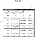
- FIG. 6 A is a diagram illustrating an example of the scanned business form list window 600 .
- This window enables viewing of a list of business forms after completion of a scan and an image analysis process and before transmission to the cloud storage 130 (S 513 of FIG. 5 ). Further, this window is formed of a scanned business form list 601 , a send button 602 , an edit button 603 , and a delete button 604 .
- the scanned business form list 601 is an area that displays a list of business forms for which a scan and an image analysis process (S 505 to S 510 ) are completed. This area is formed of fields of business form name 605 , destination 606 , status 607 , and type 608 .
- the business form name 605 is an identifier that uniquely identifies the name of a business form.
- the destination 606 is a name of the cloud storage 130 that is a destination of a file of a business form.
- the status 607 indicates a result when similar-business form determination is performed on a business form, and either “not yet learned” or “learned” is displayed.
- the “not yet learned” means that it is determined that no similar business form is present, and the “learned” means that it is determined that a similar business form is present.
- the type 608 represents the type of a business form. For example, “estimate” or “invoice” is displayed. Further, for a business form having the status 607 of “learned”, a detailed type as to which invoice format the business form corresponds to, such as “Invoice AAA” or “Invoice BBB”, is displayed. This is associated with the best similar business form determined by a similar-business form determination process.
- the send button 602 is a button used for transmitting a business form to the cloud storage 130 .
- the user may select any business form from the scanned business form list 601 and press the send button 602 to perform transmission to the cloud storage 130 displayed in the destination 606 . Note that, when transmission is successfully completed, the business form is deleted from the list.
- the edit button 603 is a button used for moving to the attribute setting window 610 described later.
- the user may select any business form from the scanned business form list 601 and press the edit button 603 , and thereby the window moves to the attribute setting window 610 ( FIG. 6 B ) for the selected business form, which enables the user to edit the attribute setting.
- the delete button 604 is a button used for deletion of a business form. The user may select any business form from the scanned business form list 601 and press the delete button 604 to delete the selected business form.
- FIG. 6 B is a diagram illustrating an example of the attribute setting window 610 (S 514 of FIG. 5 ).
- the attribute region 611 is a region in which attribute information set by the user is displayed.
- a text field 618 for entry of attribute information and a cutout image 619 of a character region described later are displayed.
- the attribute region 611 is displayed in a state where the text field is empty and no cutout image is set.
- a character region that is selectable by a click or the like may be displayed with a changed background color or displayed with a frame surrounding the selected character region so that the user can identify the character region.
- the preview region 612 displays a scanned image.
- a character region of an image is moused over, the character region is displayed with a colored frame line surrounding the character region or displayed with a changed color thereof so that the user can identify the moused-over character region.
- a character string of the character region is preliminarily displayed in the text field 618 .
- a cutout image of the character region is preliminarily displayed in the cutout image 619 .
- the text field 618 and the cutout image 619 are switched every time the moused-over character region changes.
- the frame line of a character region or a cutout image is displayed in a display form that is different from a display form applied when the selection is fixed by a click on a character region described later. Details will be described with reference to the flowchart of FIG. 7 .
- a moused-over character region is then clicked by a mouse, selection of a character region corresponding to the clicked position is fixed.
- the character region for which selection is fixed is displayed with a figure such as a line or a frame line, a background color, or the like.
- frames of the selected character regions may be displayed with different colors for respective attributes to be set, or when a plurality of character regions are selected for a single attribute, the colors of respective character regions may be different colors.
- the preview display position may be changed so that the selected character region comes to the center, or the enlargement rate may be changed.
- a character string preliminarily displayed in the text field 618 may also be displayed with a changed display color so as to visualize that the character string is fixed.
- a character string of the text field may be displayed with a gray character during preliminary display and may be displayed with a black character after fixed.
- display with a color or a frame line may be used to make a character region distinguishable. Further, display to distinguish a character region may be switched between a displayed state and a not-displayed state by a button or the like. Further, when a swipe operation is performed on a preview region, the position of an image displayed in the preview region is moved.
- the character region deletion button 613 is used for deleting a character region linked to the character region deletion button 613 and updating the attribute region 611 related to the character region. Specifically, a corresponding character string of the text field 618 is deleted, and the cutout image 619 is set to a not-set state.
- the preview enlargement button 614 enlarges the enlargement rate of an image displayed in the preview region.
- the preview reduction button 615 reduces the enlargement rate of an image displayed in the preview region. Note that the display position is adjusted such that the center coordinates of the preview region after enlargement or reduction are the same as those before the enlargement or reduction.
- the preview initial display button 616 is used for restoring the display magnification and the display position to those of the initial state if the display position of the preview image has been moved by a swipe operation or the display magnification has been changed by pressing of the preview enlargement button or the preview reduction button.
- the OK button 617 is used for transmitting a scanned image to the MFP cooperative service server 120 together with a file name set by the attribute setting window 610 and performing a machine learning process (S 515 to S 518 ). In response to completion of the transmission, the window returns to the scanned business form list window 600 .
- FIG. 7 is a flowchart illustrating details of a display process in this system when a character region is moused over. This process is repeatedly performed when the cursor is on the preview window.
- S 1 it is determined whether or not the moused-over position is in a character region. If it is determined in S 1 that the moused-over position is in a character region (Yes), the process proceeds to S 2 , and if it is determined in S 1 that the moused-over position is not in a character region (No), the process proceeds to S 7 .
- the character region being moused over is displayed so as to be identifiable by the user.
- the character region is displayed with a figure such as a line or a frame line, or the character region is displayed with a changed background color.
- a character string in the character region being moused over is extracted.
- an OCR process may be performed, and the character string may be extracted.
- an OCR process may be performed on the whole character region within the preview image in advance, or a result of character recognition process performed on the whole character region in S 510 may be acquired and used as a response to the acquisition request of the analysis result of S 513 .
- FIG. 8 A and FIG. 8 B are diagrams illustrating an example of the attribute setting window 610 .
- FIG. 8 A illustrates a case where a mouse cursor 801 is outside a region of a preview image 802 . At this point of time, neither a figure such as a frame or a line nor a color is added to the character region within the preview image 802 .
- a figure such as a frame or a line or a color is added so that the whole character region within the preview image 802 can be identified ( 803 ). Then, in this state, when the character region within a preview image is moused over as described in the first embodiment, a different color or figure from the color or figure added to the whole character region is added to the moused-over character region, and thereby the character region is displayed in an identifiable manner.
- the aspect of the embodiments has been described as a system that combines an image processing apparatus (MFP), the MFP cooperative service server, and a cloud storage, however, respective described functions may be provided in other apparatuses, respectively.
- MFP image processing apparatus
- MFP cooperative service server MFP cooperative service server
- cloud storage cloud storage
- a similar business form is determined from arrangement information on a character region of a business form
- a neural network that has learned the relationship between arrangement information on a character region and a business form may be used for performing the determination.
- the selection function of a character region of an image in the disclosure is applicable to any information processing apparatus that can display an image and on which the image can be selected.
- Embodiments of the present disclosure can also be realized by a computer of a system or apparatus that reads out and executes computer executable instructions (e.g., one or more programs) recorded on a storage medium (which may also be referred to more fully as a ‘non-transitory computer-readable storage medium’) to perform the functions of one or more of the above-described embodiments and/or that includes one or more circuits (e.g., application specific integrated circuit (ASIC)) for performing the functions of one or more of the above-described embodiments, and by a method performed by the computer of the system or apparatus by, for example, reading out and executing the computer executable instructions from the storage medium to perform the functions of one or more of the above-described embodiments and/or controlling the one or more circuits to perform the functions of one or more of the above-described embodiments.
- computer executable instructions e.g., one or more programs
- a storage medium which may also be referred to more fully as a ‘non-transitory computer-
- the computer may comprise one or more processors (e.g., central processing unit (CPU), micro processing unit (MPU)) and may include a network of separate computers or separate processors to read out and execute the computer executable instructions.
- the computer executable instructions may be provided to the computer, for example, from a network or the storage medium.
- the storage medium may include, for example, one or more of a hard disk, a random-access memory (RAM), a read only memory (ROM), a storage of distributed computing systems, an optical disk (such as a compact disc (CD), digital versatile disc (DVD), or Blu-ray Disc (BD)TM), a flash memory device, a memory card, and the like.
Landscapes
- Engineering & Computer Science (AREA)
- Multimedia (AREA)
- Signal Processing (AREA)
- Theoretical Computer Science (AREA)
- General Physics & Mathematics (AREA)
- Physics & Mathematics (AREA)
- Computer Vision & Pattern Recognition (AREA)
- Software Systems (AREA)
- Human Computer Interaction (AREA)
- Artificial Intelligence (AREA)
- Computing Systems (AREA)
- General Engineering & Computer Science (AREA)
- Facsimiles In General (AREA)
- User Interface Of Digital Computer (AREA)
- Processing Or Creating Images (AREA)
Abstract
Description
Claims (20)
Applications Claiming Priority (3)
| Application Number | Priority Date | Filing Date | Title |
|---|---|---|---|
| JP2020-067335 | 2020-04-03 | ||
| JP2020067335A JP7542980B2 (en) | 2020-04-03 | 2020-04-03 | Image processing system, image processing method and program |
| JPJP2020-067335 | 2020-04-03 |
Publications (2)
| Publication Number | Publication Date |
|---|---|
| US20210314449A1 US20210314449A1 (en) | 2021-10-07 |
| US11528372B2 true US11528372B2 (en) | 2022-12-13 |
Family
ID=77922646
Family Applications (1)
| Application Number | Title | Priority Date | Filing Date |
|---|---|---|---|
| US17/217,256 Active US11528372B2 (en) | 2020-04-03 | 2021-03-30 | Image processing system for providing attribute information, image processing method and storage medium |
Country Status (3)
| Country | Link |
|---|---|
| US (1) | US11528372B2 (en) |
| JP (1) | JP7542980B2 (en) |
| CN (1) | CN113497860B (en) |
Families Citing this family (1)
| Publication number | Priority date | Publication date | Assignee | Title |
|---|---|---|---|---|
| JP2023160049A (en) * | 2022-04-21 | 2023-11-02 | キヤノン株式会社 | information processing equipment |
Citations (5)
| Publication number | Priority date | Publication date | Assignee | Title |
|---|---|---|---|---|
| JP2001154779A (en) | 1999-11-25 | 2001-06-08 | Sharp Corp | Mouse cursor control method |
| US20020188669A1 (en) * | 2001-06-11 | 2002-12-12 | Levine Marc Jay | Integrated method for disseminating large spatial data sets in a distributed form via the internet |
| US20050251748A1 (en) * | 2003-03-24 | 2005-11-10 | Microsoft Corporation | System and method for viewing and editing multi-value properties |
| US20110286043A1 (en) * | 2010-05-24 | 2011-11-24 | Pfu Limited | Form processing system, ocr device, form creation device, and computer readable medium |
| US8953228B1 (en) * | 2013-01-07 | 2015-02-10 | Evernote Corporation | Automatic assignment of note attributes using partial image recognition results |
Family Cites Families (13)
| Publication number | Priority date | Publication date | Assignee | Title |
|---|---|---|---|---|
| US20070192719A1 (en) * | 2006-02-10 | 2007-08-16 | Microsoft Corporation | Hover indicator for objects |
| JP5491774B2 (en) * | 2009-06-12 | 2014-05-14 | 株式会社東芝 | Data entry system and data entry method |
| US9015141B2 (en) * | 2011-02-08 | 2015-04-21 | The Nielsen Company (Us), Llc | Methods, apparatus, and articles of manufacture to measure search results |
| JP2014203219A (en) * | 2013-04-03 | 2014-10-27 | 日本電信電話株式会社 | Area power consumption visualization system |
| US10146424B2 (en) * | 2014-02-28 | 2018-12-04 | Dell Products, Lp | Display of objects on a touch screen and their selection |
| JP6370162B2 (en) * | 2014-08-22 | 2018-08-08 | キヤノン株式会社 | Information processing apparatus, information processing method, and program |
| US9594489B2 (en) * | 2014-08-12 | 2017-03-14 | Microsoft Technology Licensing, Llc | Hover-based interaction with rendered content |
| KR102399764B1 (en) * | 2015-09-22 | 2022-05-19 | 삼성전자 주식회사 | Method and apparatus for capturing image |
| JP6968647B2 (en) * | 2017-10-03 | 2021-11-17 | キヤノン株式会社 | A device for setting a file name for a scanned image, its control method, and a program. |
| JP6983675B2 (en) * | 2018-01-23 | 2021-12-17 | キヤノン株式会社 | Devices, methods, programs, and systems for setting information related to scanned images |
| JP7034730B2 (en) * | 2018-01-23 | 2022-03-14 | キヤノン株式会社 | Devices, methods, and programs for setting information related to scanned images |
| JP7077127B2 (en) * | 2018-05-09 | 2022-05-30 | キヤノン株式会社 | Devices, methods, and programs for setting information related to scanned image data. |
| US10921975B2 (en) * | 2018-06-03 | 2021-02-16 | Apple Inc. | Devices, methods, and user interfaces for conveying proximity-based and contact-based input events |
-
2020
- 2020-04-03 JP JP2020067335A patent/JP7542980B2/en active Active
-
2021
- 2021-03-30 US US17/217,256 patent/US11528372B2/en active Active
- 2021-03-31 CN CN202110346079.3A patent/CN113497860B/en active Active
Patent Citations (5)
| Publication number | Priority date | Publication date | Assignee | Title |
|---|---|---|---|---|
| JP2001154779A (en) | 1999-11-25 | 2001-06-08 | Sharp Corp | Mouse cursor control method |
| US20020188669A1 (en) * | 2001-06-11 | 2002-12-12 | Levine Marc Jay | Integrated method for disseminating large spatial data sets in a distributed form via the internet |
| US20050251748A1 (en) * | 2003-03-24 | 2005-11-10 | Microsoft Corporation | System and method for viewing and editing multi-value properties |
| US20110286043A1 (en) * | 2010-05-24 | 2011-11-24 | Pfu Limited | Form processing system, ocr device, form creation device, and computer readable medium |
| US8953228B1 (en) * | 2013-01-07 | 2015-02-10 | Evernote Corporation | Automatic assignment of note attributes using partial image recognition results |
Also Published As
| Publication number | Publication date |
|---|---|
| JP7542980B2 (en) | 2024-09-02 |
| CN113497860B (en) | 2025-02-11 |
| CN113497860A (en) | 2021-10-12 |
| US20210314449A1 (en) | 2021-10-07 |
| JP2021164132A (en) | 2021-10-11 |
Similar Documents
| Publication | Publication Date | Title |
|---|---|---|
| US11616884B2 (en) | Image processing system for computerizing document, control method thereof, and storage medium | |
| JP6953230B2 (en) | A device for setting a file name, etc. on a scanned image, its control method, and a program. | |
| US12301771B2 (en) | Image processing apparatus for inputting characters using touch panel, control method thereof and storage medium | |
| US11252287B2 (en) | Image processing apparatus that displays guidance for user operation, control method thereof and storage medium | |
| US12028490B2 (en) | Server for providing a setting screen with previously used settings to a client apparatus for image transmission | |
| US11765292B2 (en) | Information processing apparatus used for converting image to file, image processing system, method of controlling information processing apparatus, and storage medium | |
| US11620840B2 (en) | Image processing apparatus for extracting a desired character string from a scanned image | |
| US11265431B2 (en) | Image processing apparatus for inputting characters using touch panel, control method thereof and storage medium | |
| US11575799B2 (en) | Image processing apparatus for setting property including character strings and separators to scanned image, control method thereof and storage medium | |
| US11528372B2 (en) | Image processing system for providing attribute information, image processing method and storage medium | |
| US11800032B2 (en) | Apparatus, information processing method, and storage medium | |
| US20230156138A1 (en) | Information processing apparatus, method of controlling information processing apparatus, and storage medium | |
| US11831824B1 (en) | Image processing apparatus, information processing apparatus, image processing system, image processing method, information processing method, and storage medium | |
| US11758060B2 (en) | Information processing apparatus, method of controlling information processing apparatus, and storage medium | |
| US20230368558A1 (en) | Image processing apparatus, image processing method, and storage medium | |
| JP2024079108A (en) | IMAGE PROCESSING APPARATUS, CONTROL METHOD AND PROGRAM FOR IMAGE PROCESSING APPARATUS | |
| JP2024072113A (en) | Information processing device, processing method and program for information processing device | |
| JP2024032563A (en) | Information processing device, control method and program for information processing device | |
| JP2023071227A (en) | Information processing device, method for controlling information processing device and program |
Legal Events
| Date | Code | Title | Description |
|---|---|---|---|
| FEPP | Fee payment procedure |
Free format text: ENTITY STATUS SET TO UNDISCOUNTED (ORIGINAL EVENT CODE: BIG.); ENTITY STATUS OF PATENT OWNER: LARGE ENTITY |
|
| AS | Assignment |
Owner name: CANON KABUSHIKI KAISHA, JAPAN Free format text: ASSIGNMENT OF ASSIGNORS INTEREST;ASSIGNOR:TOKITA, KEN;REEL/FRAME:056767/0113 Effective date: 20210610 |
|
| STPP | Information on status: patent application and granting procedure in general |
Free format text: DOCKETED NEW CASE - READY FOR EXAMINATION |
|
| STPP | Information on status: patent application and granting procedure in general |
Free format text: NON FINAL ACTION MAILED |
|
| STPP | Information on status: patent application and granting procedure in general |
Free format text: RESPONSE TO NON-FINAL OFFICE ACTION ENTERED AND FORWARDED TO EXAMINER |
|
| STPP | Information on status: patent application and granting procedure in general |
Free format text: NOTICE OF ALLOWANCE MAILED -- APPLICATION RECEIVED IN OFFICE OF PUBLICATIONS |
|
| STPP | Information on status: patent application and granting procedure in general |
Free format text: PUBLICATIONS -- ISSUE FEE PAYMENT RECEIVED |
|
| STPP | Information on status: patent application and granting procedure in general |
Free format text: PUBLICATIONS -- ISSUE FEE PAYMENT VERIFIED |
|
| STCF | Information on status: patent grant |
Free format text: PATENTED CASE |