US11515744B2 - Stator housing for an electric machine, electric machine, and vehicle - Google Patents
Stator housing for an electric machine, electric machine, and vehicle Download PDFInfo
- Publication number
- US11515744B2 US11515744B2 US16/907,635 US202016907635A US11515744B2 US 11515744 B2 US11515744 B2 US 11515744B2 US 202016907635 A US202016907635 A US 202016907635A US 11515744 B2 US11515744 B2 US 11515744B2
- Authority
- US
- United States
- Prior art keywords
- stator housing
- cooling
- portions
- deflection
- electric machine
- Prior art date
- Legal status (The legal status is an assumption and is not a legal conclusion. Google has not performed a legal analysis and makes no representation as to the accuracy of the status listed.)
- Active, expires
Links
- 238000001816 cooling Methods 0.000 claims abstract description 65
- 239000012809 cooling fluid Substances 0.000 claims abstract description 26
- 239000000463 material Substances 0.000 claims description 2
- 238000004088 simulation Methods 0.000 description 7
- 238000000926 separation method Methods 0.000 description 5
- 238000010586 diagram Methods 0.000 description 4
- 238000004804 winding Methods 0.000 description 3
- 238000010438 heat treatment Methods 0.000 description 1
- XLYOFNOQVPJJNP-UHFFFAOYSA-N water Substances O XLYOFNOQVPJJNP-UHFFFAOYSA-N 0.000 description 1
Images






Classifications
-
- H—ELECTRICITY
- H02—GENERATION; CONVERSION OR DISTRIBUTION OF ELECTRIC POWER
- H02K—DYNAMO-ELECTRIC MACHINES
- H02K1/00—Details of the magnetic circuit
- H02K1/06—Details of the magnetic circuit characterised by the shape, form or construction
- H02K1/12—Stationary parts of the magnetic circuit
- H02K1/20—Stationary parts of the magnetic circuit with channels or ducts for flow of cooling medium
-
- H—ELECTRICITY
- H02—GENERATION; CONVERSION OR DISTRIBUTION OF ELECTRIC POWER
- H02K—DYNAMO-ELECTRIC MACHINES
- H02K5/00—Casings; Enclosures; Supports
- H02K5/04—Casings or enclosures characterised by the shape, form or construction thereof
- H02K5/20—Casings or enclosures characterised by the shape, form or construction thereof with channels or ducts for flow of cooling medium
- H02K5/203—Casings or enclosures characterised by the shape, form or construction thereof with channels or ducts for flow of cooling medium specially adapted for liquids, e.g. cooling jackets
-
- B—PERFORMING OPERATIONS; TRANSPORTING
- B60—VEHICLES IN GENERAL
- B60K—ARRANGEMENT OR MOUNTING OF PROPULSION UNITS OR OF TRANSMISSIONS IN VEHICLES; ARRANGEMENT OR MOUNTING OF PLURAL DIVERSE PRIME-MOVERS IN VEHICLES; AUXILIARY DRIVES FOR VEHICLES; INSTRUMENTATION OR DASHBOARDS FOR VEHICLES; ARRANGEMENTS IN CONNECTION WITH COOLING, AIR INTAKE, GAS EXHAUST OR FUEL SUPPLY OF PROPULSION UNITS IN VEHICLES
- B60K1/00—Arrangement or mounting of electrical propulsion units
-
- H—ELECTRICITY
- H02—GENERATION; CONVERSION OR DISTRIBUTION OF ELECTRIC POWER
- H02K—DYNAMO-ELECTRIC MACHINES
- H02K9/00—Arrangements for cooling or ventilating
- H02K9/19—Arrangements for cooling or ventilating for machines with closed casing and closed-circuit cooling using a liquid cooling medium, e.g. oil
-
- H—ELECTRICITY
- H02—GENERATION; CONVERSION OR DISTRIBUTION OF ELECTRIC POWER
- H02K—DYNAMO-ELECTRIC MACHINES
- H02K2205/00—Specific aspects not provided for in the other groups of this subclass relating to casings, enclosures, supports
- H02K2205/09—Machines characterised by drain passages or by venting, breathing or pressure compensating means
-
- H—ELECTRICITY
- H02—GENERATION; CONVERSION OR DISTRIBUTION OF ELECTRIC POWER
- H02K—DYNAMO-ELECTRIC MACHINES
- H02K2213/00—Specific aspects, not otherwise provided for and not covered by codes H02K2201/00 - H02K2211/00
- H02K2213/03—Machines characterised by numerical values, ranges, mathematical expressions or similar information
Definitions
- the present invention relates to a stator housing for an electric machine, comprising a cooling channel through which a cooling fluid may flow and which has a plurality of main portions extending in the axial direction or in the circumferential direction, wherein adjacent main portions are connected by deflection portions of the cooling channel in such a way that a meandering cooling path is formed.
- the invention also relates to an electric machine and a vehicle.
- a cooling fluid in particular by means of a water cooling.
- a cooling channel through which the cooling fluid may flow and which has a meandering cooling path.
- the cooling channel for this purpose consists of main portions which extend in the axial or in the circumferential direction and which are connected in pairs by deflection portions.
- a pressure drop across the cooling path typically increases with increasing length of the cooling path or with the number of main portions and/or with the volume flow of the cooling fluid.
- the object of the invention is to describe a possibility for cooling an electric machine with which a pressure drop across a meandering cooling path is reduced.
- the invention is based on the finding that a pressure drop across the cooling path is caused quite significantly by a flow separation in the region of the deflection portions which may be significantly reduced by dividing the cooling path into the cooling sub-paths. It should be ensured here that the reduction of the pressure drop brought about by the separation of the cooling path into the cooling sub-paths is much greater than the minor increase of the pressure drop caused by the reduction of the flow cross-section on account of the addition of the guide elements.
- the stator housing according to the invention consequently enables a significant reduction of the pressure drop across the meandering cooling path and for example thus allows the use of less powerful pumps for the cooling fluid, or an increase of the volume flow of the cooling fluid and/or an increase of the number of the main portions with the same pressure drop, as compared to a conventional stator housing without guide elements.
- the deflection portions are typically designed to realise a deflection of the cooling fluid by at least 170°, preferably at least 175°, particularly preferably at least 179°.
- the cooling channel preferably has an inlet, which is connected to a first main portion on the basis of a flow direction of the cooling fluid, and/or an outlet, which is connected to a final main portion on the basis of the flow direction of the cooling fluid.
- a second guide element is formed within each of the deflection portions and separates the cooling path into a further cooling sub-path.
- the second guide element runs coaxially and/or parallel to the first guide element.
- a coaxial course typically relates to those portions of the guide elements that have a circular arc-like form
- a parallel course relates to those portions of the guide elements that have a straight course.
- the, or a, guide element follows the course of an outer and/or an inner edge of the cooling channel.
- the geometry of the deflection portion is thus advantageously transferred to the geometry of the guide element.
- The, or a, guide element is typically circular arc-shaped at least in some sections.
- the guide element may be completely circular arc-shaped. It is also possible that the guide element has a straight extension portion at one or at each end of the circular arc-shaped portion, which extension portion extends preferably into a main portion.
- the guide element expediently extends into the main portions connected by the deflection portion to an extent of at most 25%, preferably at most 10% of the length of the main portions connected by the deflection portion. It may also be provided that the guide element does not extend into the main portions connected by the deflection portion.
- the guide element or the guide elements is or are arranged centrally in the cooling channel.
- one guide element of a deflection portion separates the cooling sub-paths in fluid-tight fashion in such a way that a cooling fluid flow transverse to the flow direction of the cooling fluid through the cooling channel is prevented. Partial flow separations in the transverse direction are thus avoided. It is also possible that all guide elements of a deflection portion separate the cooling sub-paths in fluid-tight fashion.
- one guide element of a deflection portion has an aperture, in particular a central aperture, through which two of the cooling sub-channels are fluidically connected to one another. It is also possible that all guide elements of a deflection portion have an aperture.
- a deflection portion is preferably provided in the form of a sector of a ring.
- a deflection portion has a first outer edge portion running transverse to the direction of extent of the main portions and second outer edge portions which connect the first outer edge portion to edges of the main portions connected by the deflection portion.
- the first outer edge portion typically extends over at least 25%, preferably 50% of the distance between the edges of the main portions.
- the second outer edge portions may be rounded and/or may extend along the direction of extent of the main portions.
- the stator housing according to the invention may be manufactured particularly easily if the main portions and the deflection portions are formed by a cavity in the stator housing.
- the cavity may be milled into a material of the stator housing.
- the cooling channel is formed by a pipe at least in the region of the cooling path.
- the stator housing according to the invention preferably comprises an inner housing element and an outer housing element, wherein the inner housing element is arranged coaxially within the outer housing element.
- the stator housing may thus advantageously be produced in modular form.
- the cavity is preferably formed in one of the housing elements.
- the cavity is formed in the inner housing element and is closed by the outer housing element or that the cavity is formed in the outer housing element and is closed by the inner housing element.
- one of the housing elements comprises a first end plate and the other housing element comprises a second end plate of the stator housing.
- the inlet and/or the outlet is preferably formed integrally with the outer housing element. The inlet and the outlet may be provided at opposite axial positions of the stator housing.
- an electric machine for a vehicle comprising a stator housing according to the invention and a stator which is arranged within the stator housing.
- the object of the invention is also achieved by vehicle comprising an electric machine according to the invention which is designed to drive the vehicle.
- stator housing according to the invention may be transferred analogously to the electric machine according to the invention and the vehicle according to the invention, such that the above-mentioned advantages may be attained with them as well.
- FIG. 1 a schematic diagram of a first exemplary embodiment of the electric machine according to the invention with a first exemplary embodiment of the stator housing according to the invention;
- FIG. 2 shows an exploded illustration of the stator housing
- FIG. 3 shows a detailed view of a deflection portion of the stator housing
- FIG. 4 shows an illustration of flow lines of a cooling fluid during operation of the electric machine
- FIG. 5 shows an illustration corresponding to FIG. 4 during operation of a conventional electric machine according to the prior art
- FIG. 6 shows an illustration of a pressure drop of the cooling fluid during operation of the electric machine
- FIG. 7 shows an illustration corresponding to FIG. 6 during operation of the conventional electric machine
- FIG. 8 shows an illustration of a temperature distribution during operation of the electric machine
- FIG. 9 shows an illustration corresponding to FIG. 8 during operation of a conventional electric machine according to the prior art
- FIGS. 10 to 12 each show a plan view of a further exemplary embodiment of the stator housing according to the invention.
- FIG. 13 shows a schematic diagram of an exemplary embodiment of a vehicle according to the invention.
- FIG. 1 is a schematic diagram of a first exemplary embodiment of an electric machine 1 with a first exemplary embodiment of a stator housing 2 .
- the electric machine 1 also comprises a stator 3 , which is arranged in the stator housing 2 by means of a press fit.
- a rotor 4 with permanent magnets 4 a is arranged within the stator 3 and is connected to the shaft 5 for conjoint rotation.
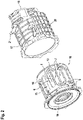
- FIG. 2 is an exploded illustration of the stator housing 2 .
- the stator housing 2 comprises a cooling channel 6 through which a cooling fluid may flow and which has a plurality of main portions 7 extending in the axial direction and a plurality of deflection portions 8 .
- the deflection portions 8 in this case connect adjacent main portions 7 in such a way that a meandering cooling path 9 is formed.
- the deflection portions 8 are arranged here alternately at opposite axial positions of the stator housing 2 .
- FIG. 3 is a detailed view of a deflection portion 8 of the stator housing 2 .
- a guide element 10 is formed within the deflection portion 8 and separates the cooling path 9 into two cooling sub-paths 11 , 12 .
- the guide element 10 follows the course of an outer edge 13 and an inner edge 14 of the cooling channel 6 .
- the deflection portion 8 is clearly provided in the form of a sector of a ring, and the guide element 10 arranged in the deflection portion is in the form of a circular arc.
- the guide element is formed from a circular arc-shaped portion 30 .
- the guide element 10 is arranged centrally in the cooling channel 6 . In the present exemplary embodiment the guide element 10 does not extend into the adjacent main portions 7 .
- the guide element extends partially into the main portion 7 , for example to an extent of 10% of the length of the main portion 7 .
- the deflection portion 8 is formed by a cavity 15 in the stator housing. It is again visible with reference to FIG. 2 that the main portions 7 are also formed by the cavity 15 .
- FIG. 2 also shows an inner housing element 16 and an outer housing element 17 of the stator housing 2 .
- the inner housing element 16 is arranged coaxially within the outer housing element 17 .
- the cavity 15 is formed in the inner housing element 16 and is closed by the outer housing element 17 .
- the cavity 15 is formed in the outer housing element 17 and is closed by the inner housing element 16 .
- the guide element 10 is formed such that it separates the cooling sub-paths 11 , 12 fluidically in such a way that a cooling fluid flow transverse to the flow direction of the cooling fluid through the cooling channel 6 is prevented. In the present exemplary embodiment, this means that the guide elements extend radially to such an extent that they reach the outer housing element 17 .
- the inner housing element 16 also has a first end plate 18 on one end face of the stator housing 2 , through which the shaft 5 (see FIG. 1 ) may be guided.
- the outer stator housing 17 on the other end face, has a second end plate 19 , which carries a further bearing for the shaft 5 (see FIG. 1 ).
- the outer housing element 17 has an inlet 20 , which is fluidically connected to a first main portion 7 , and an outlet 21 , which is fluidically connected to a last main portion 7 .
- first main portion and “last main portion” relate here to the flow direction of the cooling fluid.
- FIG. 4 , FIG. 6 and FIG. 8 are illustrations of different operating properties of the electric machine 1 in the case of an exemplary configuration with an inlet temperature of the cooling fluid of 70° C. and a volume flow of the cooling fluid of 6 l ⁇ min ⁇ 1 .
- FIG. 5 , FIG. 7 and FIG. 9 show the corresponding operating properties during operation of a conventional electric machine according to the prior art without guide elements 10 .
- FIG. 4 is an illustration of flow lines of the cooling fluid during operation of the electric machine 1 .
- FIG. 5 is a corresponding illustration during operation of the conventional electric machine. It can be seen that, due to the division of the cooling path 9 into the cooling sub-paths 11 , 12 , flow separations which lead to turbulences 22 are significantly reduced.
- FIG. 6 shows an illustration of a pressure drop of the cooling fluid during operation of the electric machine 1 .
- FIG. 7 shows a corresponding illustration during operation of the conventional electric machine.
- isolines 23 of the pressure are shown.
- the isolines 23 in the electric machine 1 according to FIG. 6 run with much greater distances than in the conventional electric machine according to FIG. 7 , which demonstrates the low pressure drop in the exemplary embodiment.
- FIG. 8 shows an illustration of a temperature distribution at the inner housing element 16 during operation of the electric machine 1 .
- FIG. 9 shows a corresponding illustration during operation of the conventional electric machine. In this case, isolines 24 of the temperature show the corresponding temperature distribution. As can be seen, due to the addition of the guide elements 11 in the electric machine 1 , there is only an insignificant increase of the temperature at the inner housing element 16 .
- the pressure drop across the cooling path is reduced from 16.2 kPa in the conventional electric machine to 5.2 kPa in the electric machine 1 . This results in a reduction of the pressure drop by 67.7%.
- the following table shows, for each of the inner housing element 16 , the outer housing element 17 and the press fit, a temperature at the location of the greatest heating ⁇ max and an average temperature ⁇ avg in both the conventional electric machine and the electric machine 1 :
- Exemplary Conventional embodiment with electric machine guide elements Inner housing ⁇ max 87.04° C. 87.17° C. element ⁇ avg 79.76° C. 79.78° C. Outer housing ⁇ max 81.56° C. 81.73° C. element ⁇ avg 76.41° C. 76.54° C. Press fit ⁇ max 87.04° C. 87.17° C. ⁇ avg 82.99° C. 83.22° C.
- the addition of the guide elements 11 leads only to a marginal temperature increase during operation of the electric machine 1 .
- stator housing 2 hereinafter, further exemplary embodiments of a stator housing 2 will be described, wherein equivalent or functionally similar components are provided with identical reference signs.
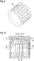
- FIG. 10 shows a plan view of a further exemplary embodiment of a stator housing 2 , which corresponds to the first exemplary embodiment apart from the deviations described hereinafter.
- the deflection portions 8 of the stator housing 2 each have a first outer edge portion 25 running transverse to the direction of extent of the main portions 7 and two second outer edge portions 26 , 27 , which connect the outer edge portion 25 to edges 20 , 29 of the main portions 7 .
- the outer edge portions 26 , 28 are rounded towards the first outer edge portion 25 and extend along the direction of extent of the main portions 7 .
- the guide element 10 in addition to the circular arc-shaped portion 30 , also has two straight extension portions 31 , 32 connected to corresponding ends of the circular arc-shaped portion 30 and extending into the main portion 7 .
- the extension portions 31 , 32 in other words form tangential continuations of the circular arc-shaped portion 30 .
- FIG. 11 is a plan view of a further exemplary embodiment of a stator housing 2 , which corresponds to the exemplary embodiment according to FIG. 10 apart from the deviations described hereinafter.
- a second guide element 10 a is additionally provided and separates the cooling path 9 into a further cooling path 12 a . Consequently, the guide elements 10 , 10 a separate the cooling path 9 into a total of three cooling paths 11 , 12 , 12 a .
- the circular arc-shaped portions 30 of the guide elements 10 , 10 a are arranged coaxially to one another, and the extension portions 31 , 32 of the guide elements 10 , 10 a are arranged parallel to one another.
- FIG. 12 is a plan view of a further exemplary embodiment of a stator housing 2 , which corresponds to the exemplary embodiment according to FIG. 11 apart from the deviations described hereinafter.
- the first guide element 10 has a central aperture 33 , which fluidically connects the cooling subchannels 11 , 12 to one another.
- Simulation results for further exemplary embodiments of the electric machine 1 which each have a stator housing 2 according to FIGS. 10, 11 and 12 will be described hereinafter.
- the exemplary configuration on which the simulation results are based differs from that on which the table shown previously was based.
- simulation results of a conventional electric machine will be described, the stator housing of which corresponds to one of the exemplary embodiments according to FIG. 10, 11 or 12 , but does not have any guide elements 10 , 10 a .
- the illustration of the simulation results is based on the following operating points:
- FIG. 10 Exemplary embodiment according to 35.21 39.58 10.59
- FIG. 11 Exemplary embodiment according to 35.29 39.27 9.88
- FIG. 12
- FIG. 12 Exemplary embodiment according to 73.92 77.40 7.00 FIG. 12
- FIG. 10 Exemplary embodiment according to 82.55 87.90 3.06
- FIG. 11 Exemplary embodiment according to 82.85 87.95 2.87
- FIG. 12
- the guide element 10 according to FIG. 10 or the guide elements 10 , 10 a according to FIG. 11 or FIG. 12 is/are used in a deflection portion 8 in the form of a sector of a ring according to the first exemplary embodiment.
- the main portions 7 extend in the circumferential direction, and the deflection portions 8 extend in the axial direction.
- the aforementioned embodiments may be transferred accordingly to a design of this kind of the stator housing 2 .
- FIG. 13 is a schematic diagram of an exemplary embodiment of a vehicle 34 .
- the vehicle 34 comprises an electric machine 1 according to the previously described exemplary embodiments, which electric machine is designed to drive the vehicle 34 .
- the vehicle 34 comprises a heat exchanger 35 and a pump 36 , which form a closed cooling circuit with the cooling channel 6 (see FIG. 1 ) of the electric machine 1 .
Landscapes
- Engineering & Computer Science (AREA)
- Power Engineering (AREA)
- Chemical & Material Sciences (AREA)
- Combustion & Propulsion (AREA)
- Transportation (AREA)
- Mechanical Engineering (AREA)
- Motor Or Generator Cooling System (AREA)
- Motor Or Generator Frames (AREA)
Applications Claiming Priority (2)
| Application Number | Priority Date | Filing Date | Title |
|---|---|---|---|
| DE102019116941.0A DE102019116941A1 (de) | 2019-06-24 | 2019-06-24 | Statorgehäuse für eine elektrische Maschine, elektrische Maschine und Fahrzeug |
| DE102019116941.0 | 2019-06-24 |
Publications (2)
| Publication Number | Publication Date |
|---|---|
| US20200403464A1 US20200403464A1 (en) | 2020-12-24 |
| US11515744B2 true US11515744B2 (en) | 2022-11-29 |
Family
ID=71105242
Family Applications (1)
| Application Number | Title | Priority Date | Filing Date |
|---|---|---|---|
| US16/907,635 Active 2041-03-09 US11515744B2 (en) | 2019-06-24 | 2020-06-22 | Stator housing for an electric machine, electric machine, and vehicle |
Country Status (5)
| Country | Link |
|---|---|
| US (1) | US11515744B2 (de) |
| EP (1) | EP3758197A1 (de) |
| JP (1) | JP2021002997A (de) |
| CN (1) | CN112134414A (de) |
| DE (1) | DE102019116941A1 (de) |
Families Citing this family (4)
| Publication number | Priority date | Publication date | Assignee | Title |
|---|---|---|---|---|
| US10923972B2 (en) * | 2017-12-01 | 2021-02-16 | American Axle & Manufacturing, Inc. | Electric motor having stator with laminations configured to form distinct cooling channels |
| CN115133713B (zh) * | 2022-08-30 | 2022-11-18 | 中山市启胜电器有限公司 | 一种可自循环降温的电机 |
| US20240178711A1 (en) * | 2022-11-29 | 2024-05-30 | Rolls-Royce Deutschland Ltd & Co Kg | Structure for an electric machine of an aircraft |
| DE102024203106B3 (de) * | 2024-04-04 | 2025-06-26 | Volkswagen Aktiengesellschaft | Statorträger, Antriebsanordnung und Kraftfahrzeug |
Citations (1)
| Publication number | Priority date | Publication date | Assignee | Title |
|---|---|---|---|---|
| EP2701286A2 (de) * | 2012-08-23 | 2014-02-26 | Robert Bosch GmbH | Gehäuse für eine elektrische Maschine mit mäanderförmigem Kühlkanal und Leitgeometrien |
Family Cites Families (8)
| Publication number | Priority date | Publication date | Assignee | Title |
|---|---|---|---|---|
| DE10112532A1 (de) * | 2001-03-15 | 2002-10-02 | Siemens Ag | Luftgekühlte elektrische rotatorische Maschine |
| JP2006014522A (ja) * | 2004-06-28 | 2006-01-12 | Nissan Motor Co Ltd | 電動機の冷却構造 |
| DE202004018968U1 (de) * | 2004-12-08 | 2005-02-10 | Bbt Thermotechnik Gmbh | Wärmetauscher |
| DE102009001387A1 (de) * | 2009-03-06 | 2010-09-09 | Robert Bosch Gmbh | Elektromaschine |
| US20130259720A1 (en) * | 2010-08-25 | 2013-10-03 | Kyle D. Mills | Electric Water Pump With Stator Cooling |
| AT510446B1 (de) * | 2010-11-18 | 2012-04-15 | Avl List Gmbh | Elektrische maschine |
| DE102011075045A1 (de) * | 2011-05-02 | 2012-11-08 | Schaeffler Technologies AG & Co. KG | Kühlmantel und Umlenkeinheit für Kühlmäntel |
| DE102016207232A1 (de) * | 2016-04-28 | 2017-11-02 | Magna powertrain gmbh & co kg | Elektrische Maschine |
-
2019
- 2019-06-24 DE DE102019116941.0A patent/DE102019116941A1/de not_active Withdrawn
-
2020
- 2020-06-11 CN CN202010530762.8A patent/CN112134414A/zh active Pending
- 2020-06-16 EP EP20180287.3A patent/EP3758197A1/de active Pending
- 2020-06-22 US US16/907,635 patent/US11515744B2/en active Active
- 2020-06-22 JP JP2020106980A patent/JP2021002997A/ja not_active Ceased
Patent Citations (1)
| Publication number | Priority date | Publication date | Assignee | Title |
|---|---|---|---|---|
| EP2701286A2 (de) * | 2012-08-23 | 2014-02-26 | Robert Bosch GmbH | Gehäuse für eine elektrische Maschine mit mäanderförmigem Kühlkanal und Leitgeometrien |
Also Published As
| Publication number | Publication date |
|---|---|
| EP3758197A1 (de) | 2020-12-30 |
| DE102019116941A1 (de) | 2020-12-24 |
| JP2021002997A (ja) | 2021-01-07 |
| US20200403464A1 (en) | 2020-12-24 |
| CN112134414A (zh) | 2020-12-25 |
Similar Documents
| Publication | Publication Date | Title |
|---|---|---|
| US20200403464A1 (en) | Stator housing for an electric machine, electric machine, and vehicle | |
| US12407206B2 (en) | Stator for electric machine, electric machine, and motor vehicle | |
| CN111725928B (zh) | 旋转电机及转子轴 | |
| JP4486114B2 (ja) | 回転電機 | |
| US10186927B2 (en) | Stator comprising an integrated radiator | |
| KR20150137027A (ko) | 전기 펌프 | |
| US11515755B2 (en) | Stator housing for an electric machine, electric machine for a vehicle and vehicle | |
| CN104769817B (zh) | 电机 | |
| RU2625727C2 (ru) | Электрическая машина с улучшенным охлаждением лобовой части обмотки | |
| US20190312475A1 (en) | Electric machine | |
| CN106464051A (zh) | 旋转电机的转子 | |
| US20190280536A1 (en) | Rotary electric machine cooling structure | |
| US20220158509A1 (en) | Compressor | |
| CN106537733A (zh) | 旋转电机 | |
| CN113826305A (zh) | 用于电机的定子的油冷系统 | |
| EP2642635A2 (de) | Flüssigkeitsgekühlte dynamoelektrische Maschine | |
| CN103746480A (zh) | 电机定子径向通风装置 | |
| CN117267138A (zh) | 流体泵 | |
| CN110620478A (zh) | 用于旋转电机的冷却装置和用于驱动车辆的旋转电机 | |
| WO2026000856A1 (zh) | 电机 | |
| US1196345A (en) | Ventilating means for dynamo-electric machines. | |
| EP2503675A1 (de) | Belüftungssystem für eine elektrische maschine | |
| CN116057815B (zh) | 旋转电机 | |
| CN211046586U (zh) | 具有制冷剂通道的马达定子结构和具有其的涡轮压缩机 | |
| JP2020182325A (ja) | 回転電機の回転子 |
Legal Events
| Date | Code | Title | Description |
|---|---|---|---|
| AS | Assignment |
Owner name: VALEO SIEMENS EAUTOMOTIVE GERMANY GMBH, GERMANY Free format text: ASSIGNMENT OF ASSIGNORS INTEREST;ASSIGNORS:KRAIS, NILS;SOENTGERATH, PHILIPP;REEL/FRAME:053000/0285 Effective date: 20200511 |
|
| FEPP | Fee payment procedure |
Free format text: ENTITY STATUS SET TO UNDISCOUNTED (ORIGINAL EVENT CODE: BIG.); ENTITY STATUS OF PATENT OWNER: LARGE ENTITY |
|
| STPP | Information on status: patent application and granting procedure in general |
Free format text: DOCKETED NEW CASE - READY FOR EXAMINATION |
|
| STPP | Information on status: patent application and granting procedure in general |
Free format text: NON FINAL ACTION MAILED |
|
| STPP | Information on status: patent application and granting procedure in general |
Free format text: RESPONSE TO NON-FINAL OFFICE ACTION ENTERED AND FORWARDED TO EXAMINER |
|
| STPP | Information on status: patent application and granting procedure in general |
Free format text: NOTICE OF ALLOWANCE MAILED -- APPLICATION RECEIVED IN OFFICE OF PUBLICATIONS |
|
| STPP | Information on status: patent application and granting procedure in general |
Free format text: PUBLICATIONS -- ISSUE FEE PAYMENT VERIFIED |
|
| STCF | Information on status: patent grant |
Free format text: PATENTED CASE |