US11510150B2 - Deriving configured output power for consecutive transmission time intervals (TTIS) in shortened TTI patterns - Google Patents
Deriving configured output power for consecutive transmission time intervals (TTIS) in shortened TTI patterns Download PDFInfo
- Publication number
- US11510150B2 US11510150B2 US16/349,519 US201716349519A US11510150B2 US 11510150 B2 US11510150 B2 US 11510150B2 US 201716349519 A US201716349519 A US 201716349519A US 11510150 B2 US11510150 B2 US 11510150B2
- Authority
- US
- United States
- Prior art keywords
- time slot
- tti
- time
- wireless device
- signal
- Prior art date
- Legal status (The legal status is an assumption and is not a legal conclusion. Google has not performed a legal analysis and makes no representation as to the accuracy of the status listed.)
- Active
Links
Images


Classifications
-
- H—ELECTRICITY
- H04—ELECTRIC COMMUNICATION TECHNIQUE
- H04L—TRANSMISSION OF DIGITAL INFORMATION, e.g. TELEGRAPHIC COMMUNICATION
- H04L5/00—Arrangements affording multiple use of the transmission path
- H04L5/003—Arrangements for allocating sub-channels of the transmission path
- H04L5/0044—Arrangements for allocating sub-channels of the transmission path allocation of payload
-
- H—ELECTRICITY
- H04—ELECTRIC COMMUNICATION TECHNIQUE
- H04L—TRANSMISSION OF DIGITAL INFORMATION, e.g. TELEGRAPHIC COMMUNICATION
- H04L5/00—Arrangements affording multiple use of the transmission path
- H04L5/003—Arrangements for allocating sub-channels of the transmission path
- H04L5/0048—Allocation of pilot signals, i.e. of signals known to the receiver
- H04L5/005—Allocation of pilot signals, i.e. of signals known to the receiver of common pilots, i.e. pilots destined for multiple users or terminals
-
- H—ELECTRICITY
- H04—ELECTRIC COMMUNICATION TECHNIQUE
- H04L—TRANSMISSION OF DIGITAL INFORMATION, e.g. TELEGRAPHIC COMMUNICATION
- H04L5/00—Arrangements affording multiple use of the transmission path
- H04L5/003—Arrangements for allocating sub-channels of the transmission path
- H04L5/0048—Allocation of pilot signals, i.e. of signals known to the receiver
- H04L5/0051—Allocation of pilot signals, i.e. of signals known to the receiver of dedicated pilots, i.e. pilots destined for a single user or terminal
-
- H—ELECTRICITY
- H04—ELECTRIC COMMUNICATION TECHNIQUE
- H04L—TRANSMISSION OF DIGITAL INFORMATION, e.g. TELEGRAPHIC COMMUNICATION
- H04L5/00—Arrangements affording multiple use of the transmission path
- H04L5/003—Arrangements for allocating sub-channels of the transmission path
- H04L5/0058—Allocation criteria
- H04L5/0064—Rate requirement of the data, e.g. scalable bandwidth, data priority
-
- H—ELECTRICITY
- H04—ELECTRIC COMMUNICATION TECHNIQUE
- H04W—WIRELESS COMMUNICATION NETWORKS
- H04W52/00—Power management, e.g. TPC [Transmission Power Control], power saving or power classes
- H04W52/04—TPC
- H04W52/18—TPC being performed according to specific parameters
-
- H—ELECTRICITY
- H04—ELECTRIC COMMUNICATION TECHNIQUE
- H04W—WIRELESS COMMUNICATION NETWORKS
- H04W52/00—Power management, e.g. TPC [Transmission Power Control], power saving or power classes
- H04W52/04—TPC
- H04W52/30—TPC using constraints in the total amount of available transmission power
- H04W52/36—TPC using constraints in the total amount of available transmission power with a discrete range or set of values, e.g. step size, ramping or offsets
- H04W52/367—Power values between minimum and maximum limits, e.g. dynamic range
-
- H—ELECTRICITY
- H04—ELECTRIC COMMUNICATION TECHNIQUE
- H04W—WIRELESS COMMUNICATION NETWORKS
- H04W72/00—Local resource management
- H04W72/04—Wireless resource allocation
- H04W72/044—Wireless resource allocation based on the type of the allocated resource
- H04W72/0446—Resources in time domain, e.g. slots or frames
-
- H—ELECTRICITY
- H04—ELECTRIC COMMUNICATION TECHNIQUE
- H04L—TRANSMISSION OF DIGITAL INFORMATION, e.g. TELEGRAPHIC COMMUNICATION
- H04L5/00—Arrangements affording multiple use of the transmission path
- H04L5/0001—Arrangements for dividing the transmission path
- H04L5/0003—Two-dimensional division
- H04L5/0005—Time-frequency
- H04L5/0007—Time-frequency the frequencies being orthogonal, e.g. OFDM(A), DMT
Definitions
- the present disclosure relates, in general, to wireless communications and, more particularly, to deriving configured output power for consecutive Transmission Time Intervals (TTIs) in shortened TTI patterns.
- TTIs Transmission Time Intervals
- LTE uses OFDM in the downlink and DFT-spread OFDM in the uplink.
- An example LTE time-domain structure is illustrated in FIG. 1 .
- the resource allocation in LTE is typically described in terms of resource blocks (RB).
- a resource block corresponds to one slot (0.5 ms) in the time domain and 12 contiguous subcarriers in the frequency domain.
- a pair of two adjacent resource blocks in time direction (1.0 ms) may be known as a resource block pair. This is also denoted as TTI (Transmission Time Interval).
- Downlink transmissions are dynamically scheduled. For example, in each subframe the base station transmits control information about to which terminals data is transmitted and upon which resource blocks the data is transmitted, in the current downlink subframe.
- CFI Control Format Indicator
- PCFICH Physical CFI channel
- the control region also contains physical downlink control channels (PDCCH) and possibly also physical HARQ indication channels (PHICH) carrying ACK/NACK for the uplink transmission.
- PDCCH physical downlink control channels
- PHICH physical HARQ indication channels
- the downlink subframe also contains common reference symbols (CRS), which are known to the receiver and used for coherent demodulation of e.g. the control information.
- CRS common reference symbols
- a Rel-8 TTI one such portion of the DL transmission is termed as one TTI.
- Uplink power control plays an important role in radio resource management which has been adopted in most modern communication systems. It balances the needs to maintain the link quality against the needs to minimize interference to other users of the system and to maximize the battery life of the terminal.
- Equation 1 the objective of power control is to determine the average power over a SC-FDMA symbol and it is applied for both common channel and dedicated channel (PUCCH/PUSCH/SRS).
- PUCCH/PUSCH/SRS common channel and dedicated channel
- P UE min ⁇ ⁇ P CMAX , ⁇ ⁇ P 0 + ⁇ ⁇ PL ⁇ open - loop ⁇ ⁇ set - point + f ⁇ ( i ) ⁇ closed - loop ⁇ ⁇ adjustment + ⁇ TF ⁇ ( i ) ⁇ MCS ⁇ ⁇ offset + 10 ⁇ log 10 ⁇ M ⁇ bandwidth ⁇ ⁇ factor ⁇ ( Equation ⁇ ⁇ 1 )
- Uplink power control is used both on the PUSCH and on PUCCH. The purpose is to ensure that the mobile terminal transmits with sufficiently high but not too high power since the latter would increase the interference to other users in the network.
- a parameterized open loop combined with a closed loop mechanism is used. Roughly, the open loop part is used to set a point of operation, around which the closed loop component operates. Different parameters (targets and ‘partial compensation factors’) for user and control plane are used.
- P PUSCHc ( i ) min ⁇ P MAX,c ,10 log 10 ( M PUSCHc ( i ))+ P O_PUSCH ( j )+ ⁇ c ⁇ PL c + ⁇ TFc ( i )+ ⁇ c ( i ) ⁇ [dBm],
- P MAX′ is the maximum transmit power for the mobile terminal
- M PUSCHc (i) is the number resource blocks assigned
- PL c is the estimated pathloss
- ⁇ TFc (i) is transport format compensator
- ⁇ c (i) is the a UE specific offset or ‘closed loop correction’ (the function ⁇ c may represent either absolute or accumulative offsets).
- the index c numbers the component carrier and is only of relevance for Carrier Aggregation.
- the closed loop power control can be operated in two different modes either accumulated or absolute. Both modes are based on TPC a command which is part of the downlink control signaling.
- the closed loop correction function is reset every time a new power control command is received.
- the power control command is a delta correction with regard to the previously accumulated closed loop correction.
- configured transmitted power PCMAX is defined in Section 6.2.5 of 3GPP TS 36.101 publicly available at www.3GPP.org as written next:
- the UE is allowed to set its configured maximum output power P CMAX,c for serving cell c.
- P-MPR c is the allowed maximum output power reduction for
- the UE shall apply P-MPR c for serving cell c only for the above cases.
- P-MPR shall be 0 dB
- P-MPR c was introduced in the P CMAX,c equation such that the UE can report to the eNB the available maximum output transmit power. This information can be used by the eNB for scheduling decisions.
- P-MPR c may impact the maximum uplink performance for the selected UL transmission path.
- the P CMAX_L,c for serving cell c is evaluated per slot and given by the minimum value taken over the transmission(s) within the slot; the minimum P CMAX_L,c over the two slots is then applied for the entire subframe.
- P PowerClass shall not be exceeded by the UE during any period of time.
- the measured configured maximum output power P UMAX,c shall be within the following bounds: P CMAX_L,c ⁇ MAX ⁇ T L ,T ( P CMAX_L,c ) ⁇ P UMAX,c ⁇ P CMAX_H,c +T ( P CMAX_H,c )
- T(P CMAX,c ) is defined by the tolerance table below and applies to P CMAX_L,c and P CMAX_H,c separately, while T L is the absolute value of the lower tolerance in Table 6.2.2-1 for the applicable operating band.
- the ⁇ T IB,c is defined for applicable bands in Table 6.2.5-2.
- Packet data latency is one of the performance metrics that vendors, operators and also end-users (via speed test applications) regularly measures. Latency measurements are done in all phases of a radio access network system lifetime, when verifying a new software release or system component, when deploying a system and when the system is in commercial operation.
- LTE Long Term Evolution
- Packet data latency is important not only for the perceived responsiveness of the system; it is also a parameter that indirectly influences the throughput of the system.
- HTTP/TCP is the dominating application and transport layer protocol suite used on the internet today. According to HTTP Archive (http://httparchive.org/trends.php) the typical size of HTTP based transactions over the internet are in the range of a few 10's of Kbyte up to 1 Mbyte. In this size range, the TCP slow start period is a significant part of the total transport period of the packet stream. During TCP slow start the performance is latency limited. Hence, improved latency can rather easily be showed to improve the average throughput, for this type of TCP based data transactions.
- Radio resource efficiency could be positively impacted by latency reductions.
- Lower packet data latency could increase the number of transmissions possible within a certain delay bound; hence higher Block Error Rate (BLER) targets could be used for the data transmissions freeing up radio resources potentially improving the capacity of the system.
- BLER Block Error Rate
- TTI transmission time interval
- SF subframe
- One such 1 ms TTI is constructed by using 14 OFDM or SC-FDMA symbols in the case of normal cyclic prefix and 12 OFDM or SC-FDMA symbols in the case of extended cyclic prefix.
- LTE release 13 a study item is starting during 2015, with the goal of specifying transmissions with shorter TTIs that are much shorter than the LTE release 8 TTI.
- the shorter TTIs can be decided to have any duration in time and comprise resources on a number of OFDM or SC-FDMA symbols within a 1 ms SF, but the slot size remains unchanged, i.e., slot size is equal to 0.5 ms.
- the duration of the short TTI may be 0.5 ms, i.e. seven OFDM or SC-FDMA symbols for the case with normal cyclic prefix.
- the duration of the short TTI may be 2 symbols.
- the TTI length consists of 14 OFDM symbols.
- the TTI length can be reduced to 2-OFDM symbols, 4-OFDM symbols or 7-OFDM symbols. These are denoted as: 2-OS sTTI, 4-OS sTTI, 7-OS sTTI, respectively.
- the shortened TTI can be used in different values in different direction, such as DL and UL.
- a DL can use 2-OS sTTI
- UL can use 4-OS sTTI in the same cell.
- FIG. 1 illustrates an example 7-symbol sTTI structure supported for UL according to agreements in R1-1611055 publicly available at www.3GPP.org. If a 4-symbol UL sTTI is supported, the sTTI structure illustrated in FIG. 4 has been adopted according to agreements in R1-1611055 publicly available at www.3GPP.org.
- FIG. 5 illustrates an example of UL TTI options.
- the above example shows a proposal for different TTI length.
- the 2-OS sTTI can have one of the two options. From UL sTTI point of view, following is observed:
- configured output power estimation timing window that is evaluated/calculated based on slots can be larger than TTI duration since the slot size of 0.5 ms remains unchanged for TTI and sTTI, i.e., shortening the TTI does not shorten the slot size of 0.5 ms.
- An example of 2-OS TTI durations are shown in FIG. 6 .
- FIG. 7 illustrates overlapping TTIs for 2-OS TTI length when the overlapping symbol is common DMRS symbol.
- FIG. 8 illustrates overlapping TTIs for 4-OS TTI length when the overlapping symbol is common DMRS symbol.
- a UE may be scheduled across two consecutive TTIs when one of the symbols of these two consecutive TTIs could be common to both TTIs. There is no rule for estimating Pcmax for such TTI arrangements.
- the configured output power is derived for one or more TTIs based on the time window corresponding to the one or more TTIs, instead of deriving the configured output power on a slot basis.
- a method for a wireless device for deriving configured output power for consecutive TTIs in shortened TTI patterns comprising:
- the determining of the TTI configuration may include obtaining the TTI configuration, such as based on pre-defined rule and/or receiving it from a network node or another wireless device.
- a wireless device for deriving configured output power for consecutive TTIs in shortened TTI patterns.
- the wireless is operable to:
- the wireless device may be further operable to obtain the TTI configuration, such as based on pre-defined rule and/or receiving it from a network node or another wireless device.
- a method for a network node for deriving configured output power for consecutive TTIs in shortened TTI patterns comprising:
- a network node for deriving configured output power for consecutive TTIs in shortened TTI patterns is provided, wherein the network node is operable to:
- the network node is further operable to use the received signal and/or the determined value of P 1 for one or more operational tasks.
- Certain embodiments of certain aspects the present disclosure may provide one or more technical advantages, such as, one or more of the following:
- a network node includes circuitry.
- the circuitry is configured to determine a Transmission Time Interval, TTI, configuration, the TTI configuration including a first TTI for operating a first signal between a first cell on a first carrier and a wireless device, and a second TTI for operating a second signal between the first cell on the first carrier and the wireless device, the TTI configuration including one of: the first TTI adjacent to the second TTI which do not overlap with each other in time; and the first TTI adjacent to the second TTI which at least partly overlap with each other in time.
- the circuitry is further configured to receive the first signal in the first TTI and the second signal in the second TTI, the first TTI and second TTI having been transmitted based on a maximum output power parameter, the single maximum output power parameter being based on the TTI configuration.
- the first TTI and the second TTI have different time lengths.
- the single maximum output power parameter is based on the time lengths of the first TTI and the second TTI.
- the first TTI and the second TTI are each a shortened TTI of less than 1 ms that are included in a subframe, the subframe having two slots where each slot is 0.5 ms.
- the first TTI is subsequent in time to the second TTI.
- the first TTI and the second TTI have a common Demodulation Reference Signal, DMRS.
- the first TTI includes one taken from a group of 2 Orthogonal Frequency Division Multiplexing (OFDM) symbols, 3 OFDM symbols, 4 OFDM symbols and 7 OFDM symbols.
- OFDM Orthogonal Frequency Division Multiplexing
- a Transmission Time Interval, TTI, configuration is determined.
- the TTI configuration includes a first TTI for operating a first signal between a first cell on a first carrier and a wireless device, and a second TTI for operating a second signal between the first cell on the first carrier and the wireless device, the TTI configuration including any of: the first TTI adjacent to the second TTI which do not overlap with each other in time; and the first TTI adjacent to the second TTI which at least partly overlap with each other in time.
- the first signal in the first TTI and the second signal in the second TTI are received, the first TTI and second TTI having been transmitted using a maximum output power, the maxim output power being based on the TTI configuration.
- the first TTI and the second TTI have different time lengths.
- the maximum output power is based on the time lengths of the first TTI and the second TTI.
- the first TTI and the second TTI are each a shortened TTI of less than 1 ms that are included in a subframe, the subframe having two slots where each slot is 0.5 ms.
- the first TTI is subsequent in time to the second TTI.
- the first TTI and the second TTI have a common Demodulation Reference Signal, DMRS.
- the first TTI includes one taken from a group of 2 Orthogonal Frequency Division Multiplexing (OFDM) symbols, 3 OFDM symbols, 4 OFDM symbols and 7 OFDM symbols.
- OFDM Orthogonal Frequency Division Multiplexing
- a wireless device comprising circuitry.
- the circuitry is configured to determine a single maximum output power parameter to be used for transmitting signals in at least two Transmission Time Intervals, TTI, based on a TTI configuration, the TTI configuration including a first TTI for operating a first signal between a first cell on a first carrier and the wireless device, and a second TTI for operating a second signal between the first cell on the first carrier and the wireless device, the TTI configuration including any of: the first TTI adjacent to the second TTI which do not overlap with each other in time; and the first TTI adjacent to the second TTI which at least partly overlap with each other in time.
- the circuitry is further configured to transmit, using the determined single maximum output power parameter, the first signal in the first TTI and the second signal in the second TTI.
- the single maximum output power parameter is based on a time length of the first TTI and a time length of the second TTI.
- the first TTI and the second TTI have different time lengths.
- the first TTI and the second TTI are each a shortened TTI of less than 1 ms that are included in a subframe, the subframe having two slots where each slot is 0.5 ms.
- the first TTI is subsequent in time to the second TTI.
- the first TTI and the second TTI have a common Demodulation Reference Signal, DMRS.
- the first TTI includes one taken from a group of 2 Orthogonal Frequency Division Multiplexing (OFDM) symbols, 3 OFDM symbols, 4 OFDM symbols and 7 OFDM symbols.
- OFDM Orthogonal Frequency Division Multiplexing
- a method for a wireless device is provided.
- a single maximum output power parameter to be used for transmitting signals in at least two Transmission Time Intervals, TTI, based on a TTI configuration is determined.
- the TTI configuration includes a first TTI for operating a first signal between a first cell on a first carrier and the wireless device, and a second TTI for operating a second signal between the first cell on the first carrier and the wireless device, the TTI configuration including any of: the first TTI adjacent to the second TTI which do not overlap with each other in time; and the first TTI adjacent to the second TTI which at least partly overlap with each other in time.
- the first signal is transmitted in the first TTI and the second signal is transmitted in the second TTI.
- the single maximum output power parameter is based on a time length of the first TTI and a time length of the second TTI.
- the first TTI and the second TTI have different time lengths.
- the first TTI and the second TTI are each a shortened TTI of less than 1 ms that are included in a subframe, the subframe having two slots where each slot is 0.5 ms.
- the first TTI is subsequent in time to the second TTI.
- the first TTI and the second TTI have a common Demodulation Reference Signal, DMRS.
- the first TTI includes one taken from a group of 2 Orthogonal Frequency Division Multiplexing (OFDM) symbols, 3 OFDM symbols, 4 OFDM symbols and 7 OFDM symbols.
- OFDM Orthogonal Frequency Division Multiplexing
- a network node includes a determining module configured to determine a Transmission Time Interval, TTI, configuration.
- the TTI configuration includes a first TTI for operating a first signal between a first cell on a first carrier and a wireless device, and a second TTI for operating a second signal between the first cell on the first carrier and the wireless device, the TTI configuration including any of: the first TTI adjacent to the second TTI which do not overlap with each other in time; and the first TTI adjacent to the second TTI which at least partly overlap with each other in time.
- the network node includes a receiving module configured to receive the first signal in the first TTI and the second signal in the second TTI, the first TTI and second TTI having been transmitted based on a maximum output power parameter, the single maximum output power parameter being based on the TTI configuration.
- a wireless device includes a power determination module configured to determine a single maximum output power parameter to be used for transmitting signals in at least two Transmission Time Intervals, TTI, based on a TTI configuration.
- the TTI configuration includes a first TTI for operating a first signal between a first cell on a first carrier and the wireless device, and a second TTI for operating a second signal between the first cell on the first carrier and the wireless device, the TTI configuration including any of: the first TTI adjacent to the second TTI which do not overlap with each other in time; and the first TTI adjacent to the second TTI which at least partly overlap with each other in time.
- the wireless device includes a transmitting module configured to transmit, using the determined single maximum output power parameter, the first signal in the first TTI and the second signal in the second TTI.
- FIG. 1 illustrates an example LTE time-domain structure
- FIG. 2 illustrates an example downlink subframe
- FIG. 3 illustrates an example 7-symbol sTTI structure supported for UL
- FIG. 4 illustrates an example, 4-symbol sTTI to be supported for UL
- FIG. 5 illustrates an example of UL TTI options
- FIG. 6 illustrates an example of 2-OS TTI durations.
- FIG. 7 illustrates overlapping TTIs for 2-OS TTI length when the overlapping symbol is common DMRS symbol
- FIG. 8 illustrates overlapping TTIs for 4-OS TTI length when the overlapping symbol is common DMRS symbol
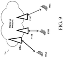
- FIG. 9 illustrates an example network for deriving configured output power for consecutive TTIs in shortened TTI patterns, according to certain embodiments.
- FIG. 10 illustrates an example wireless device for deriving configured output power for consecutive TTIs in shortened TTI patterns, according to certain embodiments
- FIG. 11 illustrates an example method for a wireless device for deriving configured output power for consecutive TTIs in shortened TTI patterns, according to certain embodiments
- FIG. 12 A illustrates an example of PCMAX estimation window for non-overlapping TTIs in 2-OS TTI pattern
- FIG. 12 B illustrates an example of PCMAX estimation window for overlapping TTIs in 2-OS TTI pattern
- FIG. 12 C illustrates an example of PCMAX estimation window for overlapping TTIs in 4-OS TTI pattern
- FIG. 13 illustrates an example virtual computing device for deriving configured output power for consecutive TTIs in shortened TTI patterns, according to certain embodiments
- FIG. 14 illustrates an example network node for deriving configured output power for consecutive TTIs in shortened TTI patterns, according to certain embodiments
- FIG. 15 illustrates an example method for a network node for deriving configured output power for consecutive TTIs in shortened TTI patterns, according to certain embodiments.
- FIG. 16 illustrates another example virtual computing device for deriving configured output power for consecutive TTIs in shortened TTI patterns, according to certain embodiments.
- FIG. 9 is a block diagram illustrating an embodiment of a network 100 for deriving configured output power with different transmission time interval (TTI) patterns, according to certain embodiments.
- Network 100 includes one or more wireless devices 110 A-C, which may be interchangeably referred to as wireless devices 110 or UEs 110 , and network nodes 115 A-C, which may be interchangeably referred to as network nodes 115 or eNodeBs 115 .
- a wireless device 110 may communicate with network nodes 115 over a wireless interface.
- wireless device 110 A may transmit wireless signals to one or more of network nodes 115 , and/or receive wireless signals from one or more of network nodes 115 .
- the wireless signals may contain voice traffic, data traffic, control signals, and/or any other suitable information.
- an area of wireless signal coverage associated with a network node 115 may be referred to as a cell.
- wireless devices 110 may have D2D capability.
- wireless devices 110 may be able to receive signals from and/or transmit signals directly to another wireless device 110 .
- wireless device 110 A may be able to receive signals from and/or transmit signals to wireless device 110 B.
- network nodes 115 may interface with a radio network controller (not depicted in FIG. 9 ).
- the radio network controller may control network nodes 115 and may provide certain radio resource management functions, mobility management functions, and/or other suitable functions.
- the functions of the radio network controller may be included in network node 115 .
- the radio network controller may interface with a core network node.
- the radio network controller may interface with the core network node via an interconnecting network.
- the interconnecting network may refer to any interconnecting system capable of transmitting audio, video, signals, data, messages, or any combination of the preceding.
- the interconnecting network may include all or a portion of a public switched telephone network (PSTN), a public or private data network, a local area network (LAN), a metropolitan area network (MAN), a wide area network (WAN), a local, regional, or global communication or computer network such as the Internet, a wireline or wireless network, an enterprise intranet, or any other suitable communication link, including combinations thereof.
- PSTN public switched telephone network
- LAN local area network
- MAN metropolitan area network
- WAN wide area network
- a local, regional, or global communication or computer network such as the Internet
- wireline or wireless network such as Wi-Fi Protectet Access
- enterprise intranet any other suitable communication link
- the core network node may manage the establishment of communication sessions and various other functionalities for wireless devices 110 .
- Wireless devices 110 may exchange certain signals with the core network node using the non-access stratum layer. In non-access stratum signaling, signals between wireless devices 110 and the core network node may be transparently passed through the radio access network.
- example embodiments of network 100 may include one or more wireless devices 110 , and one or more different types of network nodes capable of communicating (directly or indirectly) with wireless devices 110 .
- Wireless device 110 may refer to any type of wireless device communicating with a node and/or with another wireless device in a cellular or mobile communication system. Examples of wireless device 110 include a mobile phone, a smart phone, a PDA (Personal Digital Assistant), a portable computer (e.g., laptop, tablet), a sensor, a modem, a machine-type-communication (MTC) device/machine-to-machine (M2M) device, laptop embedded equipment (LEE), laptop mounted equipment (LME), USB dongles, a D2D capable device, or another device that can provide wireless communication.
- MTC machine-type-communication
- M2M machine-to-machine
- LME laptop mounted equipment
- USB dongles a D2D capable device, or another device that can provide wireless communication.
- a wireless device 110 may also be referred to as UE, a station (STA), a device, or a terminal in some embodiments.
- radio network node (or simply “network node”) is used. It can be any kind of network node, which may comprise a Node B, base station (BS), multi-standard radio (MSR) radio node such as MSR BS, eNode B, network controller, radio network controller (RNC), base station controller (BSC), relay donor node controlling relay, base transceiver station (BTS), access point (AP), transmission points, transmission nodes, RRU, RRH, nodes in distributed antenna system (DAS), core network node (e.g.
- network nodes 115 and wireless devices 110 are described in more detail with respect to FIGS. 14 and 10 , respectively.
- network 100 may include any suitable number of wireless devices 110 and network nodes 115 , as well as any additional elements suitable to support communication between wireless devices or between a wireless device and another communication device (such as a landline telephone).
- LTE long term evolution
- the embodiments may be implemented in any appropriate type of telecommunication system supporting any suitable communication standards and using any suitable components, and are applicable to any radio access technology (RAT) or multi-RAT systems in which the wireless device receives and/or transmits signals (e.g., data).
- RAT radio access technology
- multi-RAT multi-RAT
- the various embodiments described herein may be applicable to LTE, LTE-Advanced, LTE-U UMTS, HSPA, GSM, cdma2000, WiMax, WiFi, another suitable radio access technology, or any suitable combination of one or more radio access technologies.
- LTE Long Term Evolution
- LTE-A UMTS Long Term Evolution
- GSM Global System for Mobile communications
- cdma2000 Fifth Generation
- WiMax Wireless Fidelity
- WiFi wireless local area network
- another suitable radio access technology or any suitable combination of one or more radio access technologies.
- the techniques for deriving configured output power for consecutive TTIs in shortened TTI patterns described herein are applicable to both LAA LTE and standalone LTE operation in license-exempt channels and are generally applicable for transmissions from both network nodes 115 and wireless devices 110 .
- a first node and a second node are sometimes used as two nodes which are either transmitting or receiving in unlicensed spectrum (or a shared spectrum where more than one system operates based on some kind of sharing regulations).
- An example of a first node could be a network node, which could be a more general term and can correspond to any type of radio network node or any network node, which communicates with a UE and/or with another network node.
- network nodes are NodeB, base station (BS), multi-standard radio (MSR) radio node such as MSR BS, eNodeB, gNodeB.
- MeNB SeNB
- network controller radio network controller (RNC), base station controller (BSC), relay, donor node controlling relay, base transceiver station (BTS), access point (AP), transmission points, transmission nodes, RRU, RRH, nodes in distributed antenna system (DAS), core network node (e.g. MSC, MME etc.), O&M, OSS, SON, positioning node (e.g. E-SMLC), MDT etc.
- RNC radio network controller
- BSC base station controller
- BSC base station controller
- BTS base transceiver station
- AP access point
- transmission points transmission nodes
- RRU RRU
- RRH nodes in distributed antenna system
- DAS distributed antenna system
- core network node e.g. MSC, MME etc.
- O&M core network node
- OSS e.g. MSC, MME etc.
- SON positioning node
- MDT etc.
- a node could be user equipment, this is a non-limiting term user equipment (UE) and it refers to any type of wireless device communicating with a network node and/or with another UE in a cellular or mobile communication system.
- UE user equipment
- Examples of UE are target device, device to device (D2D) UE, machine type UE or UE capable of machine to machine (M2M) communication, PDA, iPAD, Tablet, mobile terminals, smart phone, laptop embedded equipped (LEE), laptop mounted equipment (LME), USB dongles etc.
- radio network node or simply “network node (NW node)”, is used. It can be any kind of network node which may comprise of base station, radio base station, base transceiver station, base station controller, network controller, evolved Node B (eNB), Node B, relay node, access point, radio access point, Remote Radio Unit (RRU) Remote Radio Head (RRH) etc.
- eNB evolved Node B
- RRU Remote Radio Unit
- RRH Remote Radio Head
- any of the above mentioned nodes could become “the first node” and/or “the second node”.
- a component carrier also interchangeably called as carrier, PCC or SCC is configured at the wireless device by the network node using higher layer signaling.
- a CC may be configured by sending a RRC configuration message to the wireless device.
- the configured CC may be used by the network node for serving the wireless device on the serving cell (e.g. on PCell, PSCell, SCell etc.) of the configured CC.
- the configured CC is also used by the wireless device for performing one or more radio measurements (e.g. RSRP, RSRQ etc.) on the cells operating on the CC e.g. PCell, SCell or PSCell and neighboring cells.
- fallback mode refers herein to a carrier aggregation (CA) configuration which contains fewer CCs than the maximum number of CCs in a CA combination supported by the wireless device 110 .
- CA carrier aggregation
- a wireless device 110 supporting a CA combination with a maximum CA configuration of 4 DL CCs and 1 UL CC may support the following 3 fallback modes: 3 DL CCs and 1 UL CC, 1 DL CCs and 1 UL CC and DL CC and 1 UL CC (i.e. single carrier operation).
- the term fallback mode is also interchangeably called as lower order CA combination, lower order CA configuration, fallback CA mode, fallback CA configuration mode, fallback CA combination etc.
- radio access technology may refer to any RAT e.g. UTRA, E-UTRA, narrow band internet of things (NB-IoT), WiFi, Bluetooth, next generation RAT (NR), 4G, 5G, etc.
- RAT may refer to any RAT e.g. UTRA, E-UTRA, narrow band internet of things (NB-IoT), WiFi, Bluetooth, next generation RAT (NR), 4G, 5G, etc.
- NB-IoT narrow band internet of things
- NR next generation RAT
- Any of the first and the second nodes may be capable of supporting a single or multiple RATs.
- signal used herein can be any physical signal or physical channel.
- Examples of physical signals are reference signal such as PSS, SSS, CRS, PRS etc.
- the term physical channel (e.g., in the context of channel reception) used herein is also called as ‘channel.
- Examples of physical channels are MIB, PBCH, NPBCH, PDCCH, PDSCH, sPUCCH, sPDSCH, sPUCCH, sPUSCH, MPDCCH, NPDCCH, NPDSCH, E-PDCCH, PUSCH, PUCCH, NPUSCH, etc.
- time resource used herein may correspond to any type of physical resource or radio resource expressed in terms of length of time. Examples of time resources are: symbol, time slot, subframe, radio frame, TTI, interleaving time, etc.
- TTI may correspond to any time period (TO) over which a physical channel can be encoded and interleaved for transmission.
- the physical channel is decoded by the receiver over the same time period (TO) over which it was encoded.
- the TTI may also interchangeably called as short TTI (sTTI), transmission time, transmission time interval, slot, sub-slot, mini-slot, short subframe (SSF), mini-subframe etc.
- Pcmax used herein may correspond to any parameter defining UE maximum output power.
- Pcmax is denoted by P 1 .
- the parameter may be pre-defined or configured.
- the parameter may be equal to or less than the nominal output power of the UE.
- Pcmax is also interchangeably called herein as UE maximum transmit power, UE maximum configured power, UE maximum operating power etc.
- the term requirements used herein may comprise any type of wireless device requirements related to wireless device measurements aka radio requirements, measurement requirements, RRM requirements, mobility requirements, positioning measurement requirements etc.
- wireless device requirements related to wireless device measurements are measurement time, measurement reporting time or delay, measurement accuracy (e.g. RSRP/RSRQ accuracy), number of cells to be measured over the measurement time etc.
- measurement time are L1 measurement period, cell identification time or cell search delay, CGI acquisition delay etc.
- a wireless device 110 may be configured with different TTI patterns.
- wireless device 110 may be configured with one serving cell (e.g. PCell) aka single carrier operation.
- Wireless device 110 may be capable of at least two different TTIs (e.g. TTI of 1 ms and TTI of 2-OS etc.).
- Wireless device 110 can be configured with any one of the plurality of TTIs supported by the wireless device 110 in one time resources in the serving cell.
- wireless device 110 may further be capable of supporting operation whereby the TTI is changed over time in the serving cell. Additionally or alternatively, wireless device 110 may further be capable of supporting operation using different TTI in uplink and downlink of the serving cell.
- Table 1 An example of the basic scenario is described in Table 1:
- TTI 2-OS is used in all in a cell continuously time resources in cell 1 2
- FIG. 10 illustrates an example wireless device 110 for deriving configured output power for consecutive TTIs in shortened TTI patterns, in accordance with certain embodiments.
- wireless device 110 includes transceiver 510 , one or more processors 520 , and memory 530 .
- transceiver 510 facilitates transmitting wireless signals to and receiving wireless signals from network node 115 (e.g., via an antenna), processor 520 executes instructions to provide some or all of the functionality described above as being provided by wireless device 110 , and memory 530 stores the instructions executed by processor 520 . Examples of a wireless device 110 are provided above.
- the one or more processors 520 may include any suitable combination of hardware and software implemented in one or more modules to execute instructions and manipulate data to perform some or all of the described functions of wireless device 110 .
- the one or more processors 520 may include, for example, one or more computers, one or more central processing units (CPUs), one or more microprocessors, one or more applications, and/or other logic.
- Memory 530 is generally operable to store instructions, such as a computer program, software, an application including one or more of logic, rules, algorithms, code, tables, etc. and/or other instructions capable of being executed by a processor.
- Examples of memory 530 include computer memory (for example, Random Access Memory (RAM) or Read Only Memory (ROM)), mass storage media (for example, a hard disk), removable storage media (for example, a Compact Disk (CD) or a Digital Video Disk (DVD)), and/or or any other volatile or non-volatile, non-transitory computer-readable and/or computer-executable memory devices that store information.
- RAM Random Access Memory
- ROM Read Only Memory
- mass storage media for example, a hard disk
- removable storage media for example, a Compact Disk (CD) or a Digital Video Disk (DVD)
- CD Compact Disk
- DVD Digital Video Disk
- wireless device 110 may include additional components beyond those shown in FIG. 10 that may be responsible for providing certain aspects of the wireless device's functionality, including any of the functionality described above and/or any additional functionality (including any functionality necessary to support the solution described above).
- FIG. 11 illustrates an exemplary method 600 for wireless device 110 for deriving configured output power for consecutive TTIs in shortened TTI patterns, according to certain embodiments.
- the method begins at step 602 , when wireless device 110 determines a single maximum output power parameter (P 1 ) to be used for transmitting signals in at least two Transmission Time Intervals, TTI, based on a TTI configuration.
- the TTI configuration includes a first TTI for operating a first signal between a first cell on a first carrier and the wireless device 110 , and a second TTI for operating a second signal between the first cell on the first carrier and the wireless device 110 .
- the TTI configuration including any of: the first TTI adjacent to the second TTI which do not overlap with each other in time; and the first TTI adjacent to the second TTI which at least partly overlap with each other in time.
- network node 115 determines a TTI configuration (TTI-CONF) comprising a first TTI (TTI 1 ) used for operating a first signal (S 1 ) between a first cell (cell 1 ) on a first carrier (F 1 ) and the UE 110 and a second TTI (TTI 2 ) used for operating a second signal (S 2 ) between a first cell (cell 1 ) on a first carrier (F 1 ).
- TTI-CONF TTI configuration
- TTI-CONF may be any of: a first TTI configuration (CONF 1 ) comprising of adjacent TTI 1 and TTI 2 which don't overlap with each other in time, and a second TTI configuration (CONF 2 ) comprising of adjacent TTI 1 and TTI 2 which at least partly overlap with each other in time.
- the determination of TTI-CONF may comprise obtaining TTI-CONF, such as based on a pre-defined rule or receiving from a network node 115 or another UE 110 .
- network node 115 transmits the TTI configuration to UE 110 .
- the wireless device 110 obtains or otherwise in one embodiment determines a TTI configuration (TTI-CONF) to be used by the wireless device 110 for at least transmitting signals in the serving cell of the wireless device 110 .
- TTI-CONF TTI configuration
- the TTI-CONF comprises of two TTIs: a first TTI (TTI 1 ) used for operating a first signal (S 1 ) between a first cell (cell 1 ) on a first carrier (F 1 ) and the UE 110 and a second TTI (TTI 2 ) used for operating a second signal (S 2 ) between a first cell (cell 1 ) on a first carrier (F 1 ), where TTI 1 and TTI 2 are adjacent or consecutive TTIs in time.
- the cell 1 can be a serving cell of the wireless device 110 . Examples of serving cells are PCell, PSCell etc. Cell 1 may correspond to UL serving cell. In this case TTI 1 corresponds to the TTI of the UL serving cell.
- the TTI-CONF may further comprise of any one of the at least two TTI configurations:
- the TTI 1 and TTI 2 used herein may refer to at least TTIs used by the wireless device 110 for transmitting uplink signals in cell 1 .
- the same TTI e.g. TTI 1
- the different TTIs may be used by the wireless device 110 for operating signals in uplink and downlink of cell 1 e.g. TTI 1 u and TTI 2 d in UL and DL respectively of cell 1 .
- the embodiments are applicable regardless of whether the same or different TTIs are used by the wireless device 110 in the same cell i.e. cell 1 .
- the term CONF 2 used herein comprises of at least TTI 1 and TTI 2 which at least partly overlap in time with each other.
- the wireless device 110 is configured with two successive or consecutive TTIs with at least one overlapping time resource (e.g. one symbol).
- TTI 1 and TTI 2 can be of the same length in time or they can of different length in time. In the latter case: in one example the leading TTI can be larger than the trailing TTI (i.e. TTI 1 >TTI 2 ) while in second example the leading TTI can be smaller than the trailing TTI (i.e. TTI 1 ⁇ TTI 2 ).
- the overlapping part of the two successive TTIs in time is typically one or more symbols containing a reference signal.
- TTI-CONF may also interchangeably called as TTI configuration comprising of two consecutive TTIs with common DMRS, TTI configuration comprising of two consecutive TTIs with shared DMRS, TTI configuration comprising of two consecutive TTIs with common or overlapping symbol(s), TTI configuration comprising of two consecutive TTIs with common or overlapping symbol(s) containing reference signals, or simply TTI configuration with common or shared DMRS or reference signal or symbols etc.
- operating signals (S 1 ) between cell 1 and the wireless device 110 may comprise of reception of signals (S 11 ) by the wireless device from cell 1 and/or transmission of signals (S 12 ) by the wireless device 110 to cell 1 .
- Examples of S 11 when receiving signals from cell 1 at the wireless device 110 are DL channels such as PDCCH, PDSCH, sPDCCH, sPDSCH etc.
- Examples of S 12 when transmitting signals by the wireless device 110 to cell 1 are UL channels such as PUCCH, PUSCH, sPUCCH, sPUSCH etc.
- the wireless device 110 may determine TTI 1 and TTI 2 comprised in the TTI-CONF based on one or more of the following mechanisms:
- the wireless device 110 determines a single maximum output power parameter (P 1 ) to be used by the UE for transmitting signals in two or more consecutive TTIs based on the determined TTI-CONF according to step 602 .
- the estimation of P 1 is done over a window or duration or an estimation period (Tw) which depends on at least at least one of the consecutive TTIs used by the UE for at least transmitting signals in its serving cell.
- the parameter Tw may also be called as reference time, reference TTI length or window, TTI reference (TTIref), Pcmax reference time, estimation period of max power etc.
- Tw TTI1+TTI1 (3)
- ⁇ t is the time duration which is shared between TTI and TTI 2 in time i.e. common between TTI 1 and TTI 2 .
- ⁇ t can be equal to the DMRS symbol if this is shared between TTI 1 and TTI 2 .
- Tw TTI+TTI2 ⁇ t (5)
- the wireless device 110 determines P CMAX_L,c for two or more consecutive TTIs and so PCMAX, c values, based on the specified requirements in TS 36.101 section 6.2.5.
- TTI duration is smaller than 1 ms (i.e. less than 14-OS TTI)
- the PCMAX is calculated for the whole duration of TTI.
- 1 ms TTI consists of 14 OFDM symbols (with normal cyclic prefix length).
- An example of the PCMAX calculation window for different TTIs is shown in table 2 below.
- the Pcmax calculation window (Tw) comprises of the time duration of TTI 1 and TTI 2 .
- TTI-CONF comprises of two consecutive TTIs (TTI 1 and TTI 2 ) with one shared OFDM symbol (e.g.
- the Pcmax calculation window (Tw) comprises of 7-OS (i.e., 0.5 ms).
- the Pcmax calculation window (Tw) comprises of 3-OS (i.e. 214.29 ⁇ s).
- the Pcmax calculation window (Tw) comprises of 3-OS (i.e. 214.29 ⁇ s).
- Cases #4 and #5 are analogous to cases #2 and #3 respectively, except that in former cases the lengths of TTI 1 and TTI 2 are different.
- the table or relation mapping or relating the values of TTI and the corresponding Pcmax parameters can be obtained by the wireless device 110 based on one or more of the following principles:
- FIGS. 12A-12C The above examples are shown in FIGS. 12A-12C .
- the total configured maximum output power PCMAX shall be set within the following bounds: P CMAX_L ⁇ P CMAX ⁇ P CMAX_H
- P CMAX_L MIN ⁇ P CMAX_L,1 (TTI( n )), P CMAX_L,1 (TTI( n+ 1), . . . , P CMAX_L,1 (TTI( n+m )), P PowereClass ⁇
- P CMAX_H MIN ⁇ P CMAX_H,1 (TTI( n )), P CMAX_H,1 (TTI( n+ 1), . . . , P CMAX_H,1 (TTI( n+m )), P PowereClass ⁇
- P CMAX_L,a(b) and P CMAX_H,a(b) are the P CMAX,c lower and higher limit respectively for cell a on TTI b.
- the number m can be defined by one or more of the following:
- the wireless device 110 uses the determined maximum output power value (P 1 ) associated with the determined TTI configuration (CONF 1 or CONF 2 ) for transmitting signals to cell 1 .
- wireless device 110 transmits, using the determined single maximum output power parameter, the first signal in the first TTI and the second signal in the second TTI.
- Wireless device 110 transmits signals S 1 and S 2 (or more signals) to cell 1 in two (or more) consecutive TTIs according to TTI-CONF based on the determined maximum output power parameter (P 1 ).
- the wireless device 110 based on the determined value of P 1 ensures that its maximum output power remains within the value, P 1 .
- the wireless device 110 based on the determined value of P 1 further ensures that its maximum output power remains within the value, P 1 when the TTI over which it transmits the signal is the same as when P 1 was estimated by the UE 110 .
- wireless device 110 uses the determined maximum output power (P 1 ) value in step-3 for one or more operational tasks. Examples of tasks are:
- the method for deriving configured output power for consecutive TTIs in shortened TTI patterns as described above may be performed by a virtual computing device.
- FIG. 13 illustrates an example virtual computing device 700 for deriving configured output power for consecutive TTIs in shortened TTI patterns, according to certain embodiments.
- virtual computing device 700 may include modules for performing steps similar to those described above with regard to the method illustrated and described in FIG. 11 .
- virtual computing device 700 may include at least one determining P 1 module 720 and at least one transmitting module 730 , and any other suitable modules for deriving configured output power for consecutive TTIs in shortened TTI patterns.
- virtual computing device 700 includes determining TTI-CONF module.
- TTI-CONF module is included in network node 115 .
- one or more of the modules may be implemented using one or more processors 520 of FIG. 10 .
- the functions of two or more of the various modules may be combined into a single module.
- wireless device 110 includes a determining TTI-CONF module that may perform the determining TTI-CONF functions of virtual computing device 700 .
- determining TTI-CONF module may perform functions according to Step 302 in FIG. 15 .
- the determining P 1 module 720 may perform the determining P 1 functions of virtual computing device 700 .
- determining P 1 module 720 may perform functions according to Step 602 in FIG. 11 .
- the transmitting module 730 may perform the transmitting functions of virtual computing device 700 .
- transmitting module 730 may perform functions according to Step 604 in FIG. 11 .
- transmitting module 730 is configured to use the determined P 1 for one or more radio operational tasks (e.g. for measurements, etc.)
- virtual computing device 700 may include additional components beyond those shown in FIG. 13 that may be responsible for providing certain aspects of the radio node's functionality, including any of the functionality described above and/or any additional functionality (including any functionality necessary to support the solutions described above).
- the various different types of wireless devices 110 and network nodes 115 may include components having the same physical hardware but configured (e.g., via programming) to support different radio access technologies, or may represent partly or entirely different physical components.
- FIG. 14 illustrate an example network node 115 for deriving configured output power for consecutive TTIs in shortened TTI patterns, according to certain embodiments.
- network node 115 may be any type of radio network node or any network node that communicates with a wireless device 110 and/or with another network node 115 . Examples of a network node 115 are provided above.
- Network nodes 115 may be deployed throughout network 100 as a homogenous deployment, heterogeneous deployment, or mixed deployment.
- a homogeneous deployment may generally describe a deployment made up of the same (or similar) type of network nodes 115 and/or similar coverage and cell sizes and inter-site distances.
- a heterogeneous deployment may generally describe deployments using a variety of types of network nodes 115 having different cell sizes, transmit powers, capacities, and inter-site distances.
- a heterogeneous deployment may include a plurality of low-power nodes placed throughout a macro-cell layout.
- Mixed deployments may include a mix of homogenous portions and heterogeneous portions.
- Network node 115 may include one or more of transceiver 210 , one or more processors 220 , memory 230 , and network interface 240 .
- transceiver 210 facilitates transmitting wireless signals to and receiving wireless signals from wireless device 110 (e.g., via an antenna)
- the one or more processors 220 execute instructions to provide some or all of the functionality described above as being provided by a network node 115
- memory 230 stores the instructions executed by the one or more processors 220
- network interface 240 communicates signals to backend network components, such as a gateway, switch, router, Internet, Public Switched Telephone Network (PSTN), core network nodes or radio network controllers, etc.
- PSTN Public Switched Telephone Network
- network node 115 may be capable of using multi-antenna techniques, and may be equipped with multiple antennas and capable of supporting MIMO techniques.
- the one or more antennas may have controllable polarization.
- each element may have two co-located sub elements with different polarizations (e.g., 90 degree separation as in cross-polarization), so that different sets of beamforming weights will give the emitted wave different polarization.
- the one or more processors 220 may include any suitable combination of hardware and software implemented in one or more modules to execute instructions and manipulate data to perform some or all of the described functions of network node 115 .
- the one or more processors 220 may include, for example, one or more computers, one or more central processing units (CPUs), one or more microprocessors, one or more applications, and/or other logic.
- Memory 230 is generally operable to store instructions, such as a computer program, software, an application including one or more of logic, rules, algorithms, code, tables, etc. and/or other instructions capable of being executed by a processor.
- Examples of memory 230 include computer memory (for example, Random Access Memory (RAM) or Read Only Memory (ROM)), mass storage media (for example, a hard disk), removable storage media (for example, a Compact Disk (CD) or a Digital Video Disk (DVD)), and/or or any other volatile or non-volatile, non-transitory computer-readable and/or computer-executable memory devices that store information.
- RAM Random Access Memory
- ROM Read Only Memory
- mass storage media for example, a hard disk
- removable storage media for example, a Compact Disk (CD) or a Digital Video Disk (DVD)
- CD Compact Disk
- DVD Digital Video Disk
- network interface 240 is communicatively coupled to the one or more processors 220 and may refer to any suitable device operable to receive input for network node 115 , send output from network node 115 , perform suitable processing of the input or output or both, communicate to other devices, or any combination of the preceding.
- Network interface 240 may include appropriate hardware (e.g., port, modem, network interface card, etc.) and software, including protocol conversion and data processing capabilities, to communicate through a network.
- network node 115 may include additional components beyond those shown in FIG. 14 that may be responsible for providing certain aspects of the radio network node's functionality, including any of the functionality described above and/or any additional functionality (including any functionality necessary to support the solutions described above).
- the various different types of network nodes may include components having the same physical hardware but configured (e.g., via programming) to support different radio access technologies, or may represent partly or entirely different physical components.
- FIG. 15 illustrates an exemplary method 300 for a network node 115 for deriving configured output power for consecutive TTIs in shortened TTI patterns, according to certain embodiments.
- the method begins at step 302 , when network node 115 determines a wireless device with a TTI configuration (TTI-CONF) comprising of a first TTI (TTI 1 ) used for operating a first signal (S 1 ) between a first cell (cell 1 ) on a first carrier (F 1 ) and the wireless device 110 and a second TTI (TTI 2 ) used for operating a second signal (S 2 ) between a first cell (cell 1 ) on a first carrier (F 1 ), wherein TTI-CONF is any of: a first TTI configuration (CONF 1 ) comprising of adjacent TTI 1 and TTI 2 which don't overlap with each other in time, and a second TTI configuration (CONF 2 ) comprising of adjacent TTI 1 and TTI 2 which at least partly overlap with each other in time.
- the TTI-CONF may further comprise of any one of the at least two TTI configurations:
- CONF 1 and CONF 2 given in section 5.3.1 (UE embodiment) are also applicable for the network node 115 .
- the network node 115 may determine the value of TTI 1 and TTI 2 or the need to configure TTI 1 and TTI 2 i.e. specific value.
- the network node 115 may determine the value of TTI 1 and TTI 2 based on for example one or more of the following principles:
- the network node 115 may determine whether to configure the wireless device 110 with CONF 1 or with CONF 2 .
- the network node 115 can determine whether to configure the wireless device 110 with CONF 1 or with CONF 2 for operating signals in cell 1 based on any of the following mechanisms:
- wireless device 110 uses the TTI configuration to determine a wireless device's maximum output power parameter (P 1 ) for two or more consecutive TTIs (TTI 1 and TTI 2 ) based on the configured values of TTI 1 and TTI 2 , as described herein.
- the parameter P 1 is used by the wireless device 110 for transmitting UL signals in cell 1 for two of more consecutive TTIs: TTI 1 and TTI 2 .
- the wireless device 110 may determine the value of P 1 based on a relation or mapping between TTIs and the maximum out power parameters.
- the mapping contains at least two TTIs and the corresponding two values of the windows (Tw) for estimating the corresponding values of the maximum output power.
- the wireless device 110 may determine the value of P 1 using the same principles as described with respect to step 602 in FIG. 11 .
- network node 115 receives the first signal in the first TTI and the second signal in the second TTI, the first TTI and second TTI having been transmitted based on a maximum output power parameter, the single maximum output power parameter being based on the TTI configuration.
- the network node 115 receives the first signal in a first cell based on the determined receiving signals S 1 and S 2 (or more signals) in cell 1 in two (or more) consecutive TTIs according to TTI-CONF from the wireless device 110 based on the determined maximum output power parameter (P 1 ).
- the network node 115 may further adapt its receiver configuration base on the value of P 1 for two or more consecutive TTIs.
- the network node 115 may use more robust receiver for receiving S 1 . But if the value of P 1 used by the wireless device 110 for transmitting signals to cell 1 is estimated by the wireless device 110 over a time window not smaller than a threshold (e.g. 300 ⁇ s), then the network node 115 may use less robust receiver for receiving S 1 .
- a more robust receiver mitigates interference more effectively compared to the receiver which is less robust.
- former receiver (which is more robust) may consume more power and requires more processing and complex operations compared to the latter receiver type.
- the adaptation of the receiver type may enable the network node to enhance the wireless device coverage.
- the network node 115 uses the received signal and/or the determined value of P 1 for one or more operational tasks. Examples of operational tasks are:
- FIG. 16 illustrates an example virtual computing device 400 for deriving configured output power for consecutive TTIs in shortened TTI patterns, according to certain embodiments.
- virtual computing device 400 may include modules for performing steps similar to those described above with regard to the method illustrated and described in FIG. 15 .
- virtual computing device 400 may include at least one configuring module, at least one determining module 420 , at least one receiving module 430 , and any other suitable modules for deriving configured output power for consecutive TTIs in shortened TTI patterns.
- one or more of the modules may be implemented using one or more processors 220 of FIG. 14 .
- the functions of two or more of the various modules may be combined into a single module.
- the determining module 420 may perform the determining functions of virtual computing device 400 .
- determining module 420 may perform functions according to Step 302 in FIG. 15 .
- virtual computing device 400 includes a configuring module that may perform the configuring wireless device 110 based on the determined TTI configuration as described herein.
- the receiving module 430 may perform the receiving functions of virtual computing device 400 .
- receiving module 430 may perform functions according to Step 304 in FIG. 15 .
- virtual computing device 400 is configured to use the received signal and/or the determined value of P 1 for one or more operational tasks.
- virtual computing device 400 may include additional components beyond those shown in FIG. 16 that may be responsible for providing certain aspects of the radio node's functionality, including any of the functionality described above and/or any additional functionality (including any functionality necessary to support the solutions described above).
- the various different types of wireless devices 110 and network nodes 115 may include components having the same physical hardware but configured (e.g., via programming) to support different radio access technologies, or may represent partly or entirely different physical components.
- a network node 115 includes circuitry.
- the circuitry is configured to determine a Transmission Time Interval, TTI, configuration, the TTI configuration including a first TTI for operating a first signal between a first cell on a first carrier and a wireless device 110 , and a second TTI for operating a second signal between the first cell on the first carrier and the wireless device 110 , the TTI configuration including any of: the first TTI adjacent to the second TTI which do not overlap with each other in time; and the first TTI adjacent to the second TTI which at least partly overlap with each other in time.
- the circuitry is further configured to receive the first signal in the first TTI and the second signal in the second TTI, the first TTI and second TTI having been transmitted based on a maximum output power parameter, the single maximum output power parameter being based on the TTI configuration.
- the first TTI and the second TTI have different time lengths.
- the single maximum output power parameter is based on the time lengths of the first TTI and the second TTI.
- the first TTI and the second TTI are each a shortened TTI of less than 1 ms that are included in a subframe, the subframe having two slots where each slot is 0.5 ms.
- the first TTI is subsequent in time to the second TTI.
- the first TTI and the second TTI have a common Demodulation Reference Signal, DMRS.
- the first TTI includes one taken from a group of 2 Orthogonal Frequency Division Multiplexing (OFDM) symbols, 3 OFDM symbols, 4 OFDM symbols and 7 OFDM symbols.
- OFDM Orthogonal Frequency Division Multiplexing
- a Transmission Time Interval, TTI, configuration is determined.
- the TTI configuration includes a first TTI for operating a first signal between a first cell on a first carrier and a wireless device 110 , and a second TTI for operating a second signal between the first cell on the first carrier and the wireless device 110 , the TTI configuration including any of: the first TTI adjacent to the second TTI which do not overlap with each other in time; and the first TTI adjacent to the second TTI which at least partly overlap with each other in time.
- the first signal in the first TTI and the second signal in the second TTI are received, the first TTI and second TTI having been transmitted using a maximum output power, the maximum output power being based on the TTI configuration.
- the first TTI and the second TTI have different time lengths.
- the maximum output power is based on the time lengths of the first TTI and the second TTI.
- the first TTI and the second TTI are each a shortened TTI of less than 1 ms that are included in a subframe, the subframe having two slots where each slot is 0.5 ms.
- the first TTI is subsequent in time to the second TTI.
- the first TTI and the second TTI have a common Demodulation Reference Signal, DMRS.
- the first TTI includes one taken from a group of 2 Orthogonal Frequency Division Multiplexing (OFDM) symbols, 3 OFDM symbols, 4 OFDM symbols and 7 OFDM symbols.
- OFDM Orthogonal Frequency Division Multiplexing
- a wireless device 110 comprising circuitry.
- the circuitry is configured to determine a single maximum output power parameter to be used for transmitting signals in at least two Transmission Time Intervals, TTI, based on a TTI configuration, the TTI configuration including a first TTI for operating a first signal between a first cell on a first carrier and the wireless device 110 , and a second TTI for operating a second signal between the first cell on the first carrier and the wireless device 110 , the TTI configuration including any of: the first TTI adjacent to the second TTI which do not overlap with each other in time; and the first TTI adjacent to the second TTI which at least partly overlap with each other in time.
- the circuitry is further configured to transmit, using the determined single maximum output power parameter, the first signal in the first TTI and the second signal in the second TTI.
- the single maximum output power parameter is based on a time length of the first TTI and a time length of the second TTI.
- the first TTI and the second TTI have different time lengths.
- the first TTI and the second TTI are each a shortened TTI of less than 1 ms that are included in a subframe, the subframe having two slots where each slot is 0.5 ms.
- the first TTI is subsequent in time to the second TTI.
- the first TTI and the second TTI have a common Demodulation Reference Signal, DMRS.
- the first TTI includes one taken from a group of 2 Orthogonal Frequency Division Multiplexing (OFDM) symbols, 3 OFDM symbols, 4 OFDM symbols and 7 OFDM symbols.
- OFDM Orthogonal Frequency Division Multiplexing
- a method for a wireless device 110 is provided.
- a single maximum output power parameter to be used for transmitting signals in at least two Transmission Time Intervals, TTI, based on a TTI configuration is determined.
- the TTI configuration includes a first TTI for operating a first signal between a first cell on a first carrier and the wireless device 110 , and a second TTI for operating a second signal between the first cell on the first carrier and the wireless device 110 , the TTI configuration including any of: the first TTI adjacent to the second TTI which do not overlap with each other in time; and the first TTI adjacent to the second TTI which at least partly overlap with each other in time.
- the first signal is transmitted in the first TTI and the second signal is transmitted in the second TTI.
- the single maximum output power parameter is based on a time length of the first TTI and a time length of the second TTI.
- the first TTI and the second TTI have different time lengths.
- the first TTI and the second TTI are each a shortened TTI of less than 1 ms that are included in a subframe, the subframe having two slots where each slot is 0.5 ms.
- the first TTI is subsequent in time to the second TTI.
- the first TTI and the second TTI have a common Demodulation Reference Signal, DMRS.
- the first TTI includes one taken from a group of 2 Orthogonal Frequency Division Multiplexing (OFDM) symbols, 3 OFDM symbols, 4 OFDM symbols and 7 OFDM symbols.
- OFDM Orthogonal Frequency Division Multiplexing
- a network node 115 includes a determining module configured to determine a Transmission Time Interval, TTI, configuration.
- the TTI configuration includes a first TTI for operating a first signal between a first cell on a first carrier and a wireless device 110 , and a second TTI for operating a second signal between the first cell on the first carrier and the wireless device 110 , the TTI configuration including any of: the first TTI adjacent to the second TTI which do not overlap with each other in time; and the first TTI adjacent to the second TTI which at least partly overlap with each other in time.
- the network node 115 includes a receiving module configured to receive the first signal in the first TTI and the second signal in the second TTI, the first TTI and second TTI having been transmitted based on a maximum output power parameter, the single maximum output power parameter being based on the TTI configuration.
- a wireless device 110 includes a power determination module configured to determine a single maximum output power parameter to be used for transmitting signals in at least two Transmission Time Intervals, TTI, based on a TTI configuration.
- the TTI configuration includes a first TTI for operating a first signal between a first cell on a first carrier and the wireless device 110 , and a second TTI for operating a second signal between the first cell on the first carrier and the wireless device 110 , the TTI configuration including any of: the first TTI adjacent to the second TTI which do not overlap with each other in time; and the first TTI adjacent to the second TTI which at least partly overlap with each other in time.
- the wireless device 110 includes a transmitting module configured to transmit, using the determined single maximum output power parameter, the first signal in the first TTI and the second signal in the second TTI.
Priority Applications (1)
| Application Number | Priority Date | Filing Date | Title |
|---|---|---|---|
| US16/349,519 US11510150B2 (en) | 2016-11-14 | 2017-11-14 | Deriving configured output power for consecutive transmission time intervals (TTIS) in shortened TTI patterns |
Applications Claiming Priority (3)
| Application Number | Priority Date | Filing Date | Title |
|---|---|---|---|
| US201662421582P | 2016-11-14 | 2016-11-14 | |
| PCT/IB2017/057116 WO2018087742A1 (en) | 2016-11-14 | 2017-11-14 | Deriving configured output power for consecutive transmission time intervals (ttis) in shortened tti patterns |
| US16/349,519 US11510150B2 (en) | 2016-11-14 | 2017-11-14 | Deriving configured output power for consecutive transmission time intervals (TTIS) in shortened TTI patterns |
Publications (2)
| Publication Number | Publication Date |
|---|---|
| US20190342840A1 US20190342840A1 (en) | 2019-11-07 |
| US11510150B2 true US11510150B2 (en) | 2022-11-22 |
Family
ID=60627971
Family Applications (1)
| Application Number | Title | Priority Date | Filing Date |
|---|---|---|---|
| US16/349,519 Active US11510150B2 (en) | 2016-11-14 | 2017-11-14 | Deriving configured output power for consecutive transmission time intervals (TTIS) in shortened TTI patterns |
Country Status (6)
| Country | Link |
|---|---|
| US (1) | US11510150B2 (ru) |
| EP (1) | EP3539252B1 (ru) |
| JP (1) | JP6756042B2 (ru) |
| CN (2) | CN115834009A (ru) |
| RU (1) | RU2713377C9 (ru) |
| WO (1) | WO2018087742A1 (ru) |
Families Citing this family (5)
| Publication number | Priority date | Publication date | Assignee | Title |
|---|---|---|---|---|
| CN111436108B (zh) * | 2019-01-11 | 2022-02-25 | 华为技术有限公司 | 一种功率控制的方法以及功率控制的装置 |
| CN111757448B (zh) * | 2019-03-29 | 2021-09-07 | 华为技术有限公司 | 一种功率控制方法及装置 |
| CN112492274B (zh) * | 2020-11-26 | 2021-08-17 | 江南大学 | 一种基于普通网络摄像机的国密加密传输设备 |
| US11533688B2 (en) * | 2021-03-17 | 2022-12-20 | T-Mobile Usa, Inc. | Dynamic switching of user equipment power class |
| CN114339867B (zh) * | 2021-12-31 | 2024-03-19 | 哲库科技(北京)有限公司 | 小区测量方法、装置、终端设备及存储介质 |
Citations (9)
| Publication number | Priority date | Publication date | Assignee | Title |
|---|---|---|---|---|
| CN101663852A (zh) | 2007-04-20 | 2010-03-03 | 高通股份有限公司 | 用于动态调整上行链路传输时间的方法和装置 |
| RU2385534C2 (ru) | 2005-08-05 | 2010-03-27 | Нокиа Корпорейшн | Длина преамбулы для прерывистой передачи по каналу управления |
| US20130242889A1 (en) * | 2012-03-16 | 2013-09-19 | Alexey Khoryaev | Physical uplink shared channel (pusch) transmission time interval (tti) bundling |
| WO2015116866A1 (en) | 2014-01-29 | 2015-08-06 | Interdigital Patent Holdings, Inc. | Uplink transmissions in wireless communications |
| CN105933100A (zh) | 2016-06-27 | 2016-09-07 | 珠海市魅族科技有限公司 | Harq 反馈方法及装置、基站和终端 |
| US20170290008A1 (en) * | 2014-09-08 | 2017-10-05 | Interdigital Patent Holdings, Inc. | Systems and Methods of Operating with Different Transmission Time Interval (TTI) Durations |
| WO2018027540A1 (en) * | 2016-08-09 | 2018-02-15 | Panasonic Intellectual Property Corporation Of America | Terminal and communication method |
| US20180098337A1 (en) * | 2015-04-08 | 2018-04-05 | Lg Electronics Inc. | Method for transmitting and receiving data in wireless communicaton system and apparatus for the same |
| US20180213489A1 (en) * | 2015-08-21 | 2018-07-26 | Ntt Docomo, Inc. | User device, base station, communication method, and instruction method |
-
2017
- 2017-11-14 US US16/349,519 patent/US11510150B2/en active Active
- 2017-11-14 CN CN202211419258.6A patent/CN115834009A/zh active Pending
- 2017-11-14 CN CN201780082912.XA patent/CN110192372B/zh active Active
- 2017-11-14 EP EP17811382.5A patent/EP3539252B1/en active Active
- 2017-11-14 RU RU2019118307A patent/RU2713377C9/ru active
- 2017-11-14 WO PCT/IB2017/057116 patent/WO2018087742A1/en active Search and Examination
- 2017-11-14 JP JP2019524993A patent/JP6756042B2/ja active Active
Patent Citations (9)
| Publication number | Priority date | Publication date | Assignee | Title |
|---|---|---|---|---|
| RU2385534C2 (ru) | 2005-08-05 | 2010-03-27 | Нокиа Корпорейшн | Длина преамбулы для прерывистой передачи по каналу управления |
| CN101663852A (zh) | 2007-04-20 | 2010-03-03 | 高通股份有限公司 | 用于动态调整上行链路传输时间的方法和装置 |
| US20130242889A1 (en) * | 2012-03-16 | 2013-09-19 | Alexey Khoryaev | Physical uplink shared channel (pusch) transmission time interval (tti) bundling |
| WO2015116866A1 (en) | 2014-01-29 | 2015-08-06 | Interdigital Patent Holdings, Inc. | Uplink transmissions in wireless communications |
| US20170290008A1 (en) * | 2014-09-08 | 2017-10-05 | Interdigital Patent Holdings, Inc. | Systems and Methods of Operating with Different Transmission Time Interval (TTI) Durations |
| US20180098337A1 (en) * | 2015-04-08 | 2018-04-05 | Lg Electronics Inc. | Method for transmitting and receiving data in wireless communicaton system and apparatus for the same |
| US20180213489A1 (en) * | 2015-08-21 | 2018-07-26 | Ntt Docomo, Inc. | User device, base station, communication method, and instruction method |
| CN105933100A (zh) | 2016-06-27 | 2016-09-07 | 珠海市魅族科技有限公司 | Harq 反馈方法及装置、基站和终端 |
| WO2018027540A1 (en) * | 2016-08-09 | 2018-02-15 | Panasonic Intellectual Property Corporation Of America | Terminal and communication method |
Non-Patent Citations (14)
| Title |
|---|
| 3GPP TS 36.101 V14.1.0 (Sep. 2016); 3rd Generation Partnership Project; Technical Specification Group Radio Access Network; Evolved Univeral Terrestrial Radio Access (E-UTRA); User Equipment UE Radio Transmission and Reception (Release 14), consisting of 1187 pages. |
| 3GPP TS 36.331 V14.0.0 (Sep. 2016); 3rd Generation Partnership Project; Technical Specification Group Radio Access Network; Evolved Universal Terrestrial Radio Access (E-UTRA); Radio Resource Control (RRC); Protocol Specification (Release 14), consisting of 644 pages. |
| 3GPP TSG RAN WG1 Meeting #86; R1-166153; Agenda Item: 7.2.12.2.1; Source: Huawei, HiSilicon; Title: PUSCH Design for Short TTI; Document for: Discussion and Decision, consisting of 3 pages. |
| 3GPP TSG-RAN WG1 #86 bis, Lisbon, Portugal Oct. 10-14, 2016; R1-1611055; Source: RAN1; Title: LS on Shortened TTI and Processing Time for LTE; Release 15; Work Item: LTE_sTTIandPT, consisting of 4 pages. |
| 3GPP TSG-RAN WG1 #87, Reno, US Nov. 14-18, 2016; R1-1611530; Agenda Item: 6.2.10.2.5; Source Ericsson; Title: Possible RF Impacts Related to sPUSCH Design; Document for Discussion, Decision, consisting of 2 pages. |
| 3GPP TSG-RAN WG4 #81, Reno, Nevada, USA, Nov. 14-18, 2016; R4-1610470; Agenda Item: 10.1.2; Source Ericsson; Title: UL Power Control Issues Related to Shortened TTI Patterns; Document for Discussion, consisting of 4 pages. |
| Chinese Office Action and English translation dated May 21, 2021 issued in corresponding Chinese Patent Application No. 201780082912.X, consisting of 14 pages. |
| European Communication Pursuant to Article 94(3) EPC dated Mar. 15, 2021 issued in corresponding European Patent Application No. 17 811 382.5, consisting of 5 pages. |
| Huawei, HiSilicon; 3GPP TSG RAN WG1 Meeting #87; R1-1611161; Agenda Item: 6.2.10.2.7; Title: "UL Power Control for Short TTI"; Document for: Discussion and Decision; Reno, USA, Nov. 14-18, 2016, consisting of 5 pages. |
| Indian First Examination Report dated Jan. 19, 2021 issued in corresponding Indian Patent Application No. 201947022646, consisting of 5 pages. |
| International Search Report and Written Opinion of the International Searching Authority dated Feb. 14, 2018 Bsued in PCT Application No. PCT/IB2017/057116, consisting of 14 pages. |
| Notification of the Transmittal of the International Preliminary Report on Patentability dated May 2, 2019 issued in PCT Application No. PCT/IB2017/057116, consisting of 31 pages. |
| Russian Decision on Grant and Search Report issued in Russian Application No. 2019118307 dated Oct. 24, 2019 consisting of 25 pages. |
| Written Opinion of the International Preliminary Examining Authority dated Nov. 12, 2018 issued in PCT Application No. PCT/IB2017/057116, consisting of 7 pages. |
Also Published As
| Publication number | Publication date |
|---|---|
| US20190342840A1 (en) | 2019-11-07 |
| CN110192372A (zh) | 2019-08-30 |
| CN115834009A (zh) | 2023-03-21 |
| RU2713377C9 (ru) | 2020-02-18 |
| JP6756042B2 (ja) | 2020-09-16 |
| RU2713377C1 (ru) | 2020-02-05 |
| WO2018087742A1 (en) | 2018-05-17 |
| JP2020502890A (ja) | 2020-01-23 |
| EP3539252B1 (en) | 2023-09-13 |
| CN110192372B (zh) | 2022-12-02 |
| EP3539252A1 (en) | 2019-09-18 |
Similar Documents
| Publication | Publication Date | Title |
|---|---|---|
| CN110637485B (zh) | 用于无线功率控制的系统和方法 | |
| US9894621B2 (en) | Power headroom reporting accounting | |
| US11510150B2 (en) | Deriving configured output power for consecutive transmission time intervals (TTIS) in shortened TTI patterns | |
| KR102006088B1 (ko) | 이중 연결에서의 pcmax 도출 | |
| US10827427B2 (en) | On/off time mask for short TTI | |
| US20200007370A1 (en) | Adapting UE On/Off Transient Time Parameter for Different Transmission Time Interval Patterns | |
| US11647400B2 (en) | Systems and methods for identifying CE level mismatch | |
| US20210099959A1 (en) | Deriving configured output powers with overlapping durations under uplink pre-emption | |
| EP3536054B1 (en) | Deriving configured output power with different tti | |
| EP3520501B1 (en) | Systems and methods for power allocation in uplink multicarrier scenarios for mixed transmission time intervals |
Legal Events
| Date | Code | Title | Description |
|---|---|---|---|
| FEPP | Fee payment procedure |
Free format text: ENTITY STATUS SET TO UNDISCOUNTED (ORIGINAL EVENT CODE: BIG.); ENTITY STATUS OF PATENT OWNER: LARGE ENTITY |
|
| AS | Assignment |
Owner name: TELEFONAKTIEBOLAGET LM ERICSSON (PUBL), SWEDEN Free format text: ASSIGNMENT OF ASSIGNORS INTEREST;ASSIGNOR:ERICSSON LIMITED;REEL/FRAME:049196/0071 Effective date: 20161110 Owner name: TELEFONAKTIEBOLAGET LM ERICSSON (PUBL), SWEDEN Free format text: ASSIGNMENT OF ASSIGNORS INTEREST;ASSIGNORS:RAHMAN, IMADUR;BERGLJUNG, CHRISTIAN;EVERAERE, DOMINIQUE;AND OTHERS;SIGNING DATES FROM 20180118 TO 20180329;REEL/FRAME:049199/0028 Owner name: ERICSSON LIMITED, GREAT BRITAIN Free format text: ASSIGNMENT OF ASSIGNORS INTEREST;ASSIGNOR:CALLENDER, CHRISTOPHER;REEL/FRAME:049195/0973 Effective date: 20161110 |
|
| STPP | Information on status: patent application and granting procedure in general |
Free format text: NON FINAL ACTION MAILED |
|
| STPP | Information on status: patent application and granting procedure in general |
Free format text: RESPONSE TO NON-FINAL OFFICE ACTION ENTERED AND FORWARDED TO EXAMINER |
|
| STPP | Information on status: patent application and granting procedure in general |
Free format text: FINAL REJECTION MAILED |
|
| STPP | Information on status: patent application and granting procedure in general |
Free format text: DOCKETED NEW CASE - READY FOR EXAMINATION |
|
| STPP | Information on status: patent application and granting procedure in general |
Free format text: NOTICE OF ALLOWANCE MAILED -- APPLICATION RECEIVED IN OFFICE OF PUBLICATIONS |
|
| STPP | Information on status: patent application and granting procedure in general |
Free format text: PUBLICATIONS -- ISSUE FEE PAYMENT VERIFIED |
|
| STCF | Information on status: patent grant |
Free format text: PATENTED CASE |