US11510103B2 - Method and apparatus for load balancing in a Cloud-radio access network - Google Patents
Method and apparatus for load balancing in a Cloud-radio access network Download PDFInfo
- Publication number
- US11510103B2 US11510103B2 US16/769,637 US201716769637A US11510103B2 US 11510103 B2 US11510103 B2 US 11510103B2 US 201716769637 A US201716769637 A US 201716769637A US 11510103 B2 US11510103 B2 US 11510103B2
- Authority
- US
- United States
- Prior art keywords
- user
- user equipment
- network function
- virtualized network
- function component
- Prior art date
- Legal status (The legal status is an assumption and is not a legal conclusion. Google has not performed a legal analysis and makes no representation as to the accuracy of the status listed.)
- Active
Links
- 238000000034 method Methods 0.000 title claims abstract description 55
- 230000006870 function Effects 0.000 claims description 70
- 230000005012 migration Effects 0.000 claims description 29
- 238000013508 migration Methods 0.000 claims description 29
- 230000003068 static effect Effects 0.000 claims description 11
- 230000006855 networking Effects 0.000 claims description 9
- 238000007689 inspection Methods 0.000 claims description 6
- 238000004891 communication Methods 0.000 description 13
- 230000008569 process Effects 0.000 description 13
- 238000012545 processing Methods 0.000 description 10
- 230000005540 biological transmission Effects 0.000 description 9
- 240000002791 Brassica napus Species 0.000 description 5
- 238000004590 computer program Methods 0.000 description 5
- 230000011664 signaling Effects 0.000 description 5
- 230000008901 benefit Effects 0.000 description 4
- 238000005096 rolling process Methods 0.000 description 4
- 238000012423 maintenance Methods 0.000 description 3
- 230000003287 optical effect Effects 0.000 description 3
- 230000005641 tunneling Effects 0.000 description 3
- 230000001174 ascending effect Effects 0.000 description 2
- 239000000872 buffer Substances 0.000 description 2
- 230000001413 cellular effect Effects 0.000 description 2
- 238000005516 engineering process Methods 0.000 description 2
- 230000036541 health Effects 0.000 description 2
- 238000007726 management method Methods 0.000 description 2
- 230000004044 response Effects 0.000 description 2
- 235000006719 Cassia obtusifolia Nutrition 0.000 description 1
- 244000201986 Cassia tora Species 0.000 description 1
- 235000014552 Cassia tora Nutrition 0.000 description 1
- 241000700605 Viruses Species 0.000 description 1
- 238000012217 deletion Methods 0.000 description 1
- 230000037430 deletion Effects 0.000 description 1
- 238000010586 diagram Methods 0.000 description 1
- 238000005265 energy consumption Methods 0.000 description 1
- 230000004941 influx Effects 0.000 description 1
- 230000003993 interaction Effects 0.000 description 1
- 230000007774 longterm Effects 0.000 description 1
- 230000007246 mechanism Effects 0.000 description 1
- 238000010295 mobile communication Methods 0.000 description 1
- 238000012986 modification Methods 0.000 description 1
- 230000004048 modification Effects 0.000 description 1
- 238000012544 monitoring process Methods 0.000 description 1
- 239000013307 optical fiber Substances 0.000 description 1
- 239000004065 semiconductor Substances 0.000 description 1
- 230000001960 triggered effect Effects 0.000 description 1
Images


Classifications
-
- H04W28/0842—
-
- H—ELECTRICITY
- H04—ELECTRIC COMMUNICATION TECHNIQUE
- H04W—WIRELESS COMMUNICATION NETWORKS
- H04W28/00—Network traffic management; Network resource management
- H04W28/02—Traffic management, e.g. flow control or congestion control
- H04W28/08—Load balancing or load distribution
- H04W28/088—Load balancing or load distribution among core entities
-
- H—ELECTRICITY
- H04—ELECTRIC COMMUNICATION TECHNIQUE
- H04L—TRANSMISSION OF DIGITAL INFORMATION, e.g. TELEGRAPHIC COMMUNICATION
- H04L45/00—Routing or path finding of packets in data switching networks
- H04L45/64—Routing or path finding of packets in data switching networks using an overlay routing layer
-
- H—ELECTRICITY
- H04—ELECTRIC COMMUNICATION TECHNIQUE
- H04L—TRANSMISSION OF DIGITAL INFORMATION, e.g. TELEGRAPHIC COMMUNICATION
- H04L12/00—Data switching networks
- H04L12/28—Data switching networks characterised by path configuration, e.g. LAN [Local Area Networks] or WAN [Wide Area Networks]
- H04L12/46—Interconnection of networks
- H04L12/4633—Interconnection of networks using encapsulation techniques, e.g. tunneling
-
- H—ELECTRICITY
- H04—ELECTRIC COMMUNICATION TECHNIQUE
- H04L—TRANSMISSION OF DIGITAL INFORMATION, e.g. TELEGRAPHIC COMMUNICATION
- H04L12/00—Data switching networks
- H04L12/28—Data switching networks characterised by path configuration, e.g. LAN [Local Area Networks] or WAN [Wide Area Networks]
- H04L12/46—Interconnection of networks
- H04L12/4641—Virtual LANs, VLANs, e.g. virtual private networks [VPN]
-
- H—ELECTRICITY
- H04—ELECTRIC COMMUNICATION TECHNIQUE
- H04L—TRANSMISSION OF DIGITAL INFORMATION, e.g. TELEGRAPHIC COMMUNICATION
- H04L45/00—Routing or path finding of packets in data switching networks
- H04L45/38—Flow based routing
-
- H—ELECTRICITY
- H04—ELECTRIC COMMUNICATION TECHNIQUE
- H04W—WIRELESS COMMUNICATION NETWORKS
- H04W28/00—Network traffic management; Network resource management
- H04W28/02—Traffic management, e.g. flow control or congestion control
- H04W28/08—Load balancing or load distribution
-
- H04W28/0804—
-
- H—ELECTRICITY
- H04—ELECTRIC COMMUNICATION TECHNIQUE
- H04W—WIRELESS COMMUNICATION NETWORKS
- H04W28/00—Network traffic management; Network resource management
- H04W28/02—Traffic management, e.g. flow control or congestion control
- H04W28/08—Load balancing or load distribution
- H04W28/084—Load balancing or load distribution among network function virtualisation [NFV] entities; among edge computing entities, e.g. multi-access edge computing
-
- H—ELECTRICITY
- H04—ELECTRIC COMMUNICATION TECHNIQUE
- H04W—WIRELESS COMMUNICATION NETWORKS
- H04W28/00—Network traffic management; Network resource management
- H04W28/02—Traffic management, e.g. flow control or congestion control
- H04W28/08—Load balancing or load distribution
- H04W28/086—Load balancing or load distribution among access entities
-
- H—ELECTRICITY
- H04—ELECTRIC COMMUNICATION TECHNIQUE
- H04W—WIRELESS COMMUNICATION NETWORKS
- H04W28/00—Network traffic management; Network resource management
- H04W28/02—Traffic management, e.g. flow control or congestion control
- H04W28/08—Load balancing or load distribution
- H04W28/09—Management thereof
- H04W28/0958—Management thereof based on metrics or performance parameters
-
- H—ELECTRICITY
- H04—ELECTRIC COMMUNICATION TECHNIQUE
- H04W—WIRELESS COMMUNICATION NETWORKS
- H04W36/00—Hand-off or reselection arrangements
- H04W36/0005—Control or signalling for completing the hand-off
- H04W36/0011—Control or signalling for completing the hand-off for data sessions of end-to-end connection
- H04W36/0033—Control or signalling for completing the hand-off for data sessions of end-to-end connection with transfer of context information
-
- H—ELECTRICITY
- H04—ELECTRIC COMMUNICATION TECHNIQUE
- H04W—WIRELESS COMMUNICATION NETWORKS
- H04W36/00—Hand-off or reselection arrangements
- H04W36/02—Buffering or recovering information during reselection ; Modification of the traffic flow during hand-off
-
- H—ELECTRICITY
- H04—ELECTRIC COMMUNICATION TECHNIQUE
- H04W—WIRELESS COMMUNICATION NETWORKS
- H04W76/00—Connection management
- H04W76/10—Connection setup
- H04W76/15—Setup of multiple wireless link connections
-
- H—ELECTRICITY
- H04—ELECTRIC COMMUNICATION TECHNIQUE
- H04W—WIRELESS COMMUNICATION NETWORKS
- H04W80/00—Wireless network protocols or protocol adaptations to wireless operation
- H04W80/02—Data link layer protocols
Definitions
- Embodiments of the disclosure generally relate to wireless communication, and, more particularly, to method and apparatus for load balancing in a Cloud-radio access network (C-RAN).
- C-RAN Cloud-radio access network
- C-RAN is a novel mobile network architecture where baseband processing is centralized and shared among sites in a virtualized BBU (Building Base band Unit) or user equipment (UE) virtualized network function component (VNFC) Pool. This means that it is able to adapt to non-uniform traffic and utilize resources more efficiently. Due to the fact that fewer UE VNFCs are needed in C-RAN compared to the traditional architecture, C-RAN has also the potential to decrease the cost of network operation, because power and energy consumption are reduced compared to the traditional RAN architecture. New UE VNFC can be added and upgraded easily, thereby improving scalability and easing network maintenance. The UE VNFC Pool can be shared by different network operators, allowing them to rent RAN as a cloud service.
- BBU Building Base band Unit
- UE user equipment
- VNFC virtualized network function component
- UE related control-plane (CP) and user-plane (UP) functionality closely engage with a core network, radio access points and cell specific or central control plane logic etc., which may result in that the procedures of user migration inside C-RAN, UE VNFCs' scale-in/out, rolling upgrade/fall back, load balancing or high availability all have impacts to these “partners” (core network, radio access points, cell specific and central control plane applications) and become much more complex. Therefore, it would be desirable to provide an improved solution for C-RAN.
- a method for load balancing in a Cloud-radio access network comprises receiving control plane (CP) data associated with a user from a core network or a remote access point; and dispatching the CP data to a first user equipment (UE) virtualized network function component (VNFC) based on a first route.
- CP control plane
- UE user equipment
- VNFC virtualized network function component
- an apparatus for managing sharing vehicle comprises a processor; and a memory, the memory containing instructions executable by the processor, whereby the apparatus is operative to receive control plane (CP) data associated with a user from a core network or a remote access point; and dispatch the CP data to a first user equipment (UE) virtualized network function component (VNFC) based on a first route.
- CP control plane
- UE user equipment
- VNFC virtualized network function component
- the computer program product comprises instructions which when executed by at least one processor, cause the at least one processor to receive control plane (CP) data associated with a user from a core network or a remote access point; and dispatch the CP data to a first user equipment (UE) virtualized network function component (VNFC) based on a first route.
- CP control plane
- UE user equipment
- VNFC virtualized network function component
- the computer readable storage medium comprises instructions which when executed by at least one processor, cause the at least one processor to receive control plane (CP) data associated with a user from a core network or a remote access point; and dispatch the CP data to a first user equipment (UE) virtualized network function component (VNFC) based on a first route.
- CP control plane
- UE user equipment
- VNFC virtualized network function component
- FIG. 1 depicts a schematic LTE system without a load balancer
- FIG. 2 depicts a schematic protocol stack of the schematic LTE system without a load balancer
- FIG. 3 depicts a schematic system, in which some embodiments of the present disclosure can be implemented
- FIG. 4 depicts a schematic load balancer according to an embodiment of the present disclosure
- FIG. 5 depicts a schematic protocol stack of a LTE system with a load balancer according to an embodiment of the present disclosure
- FIG. 6A is a flow chart depicting a method according to an embodiment of the present disclosure.
- FIG. 6B is a flow chart depicting a method according to another embodiment of the present disclosure.
- FIG. 7 is a flow chart depicting a method according to another embodiment of the present disclosure.
- FIG. 8 is a flow chart depicting a method for user migration according to another embodiment of the present disclosure.
- FIG. 9 is a flow chart depicting a method for user migration according to an embodiment of the present disclosure.
- FIG. 10 is a flow chart depicting a method for providing high availability according to another embodiment of the present disclosure.
- FIG. 11 is a flow chart depicting a process for providing high availability according to an embodiment of the present disclosure.
- FIG. 12 is a block diagram illustrating an apparatus according to an embodiment of the disclosure.
- FIG. 13 depicts a schematic system, in which the dispatching functionality of the load balancer is implemented by a SDN vSwitch.
- wireless network or “radio network” refers to a network following any suitable communication standards, such as LTE-Advanced (LTE-A), LTE, Wideband Code Division Multiple Access (WCDMA), High-Speed Packet Access (HSPA), and so on.
- LTE-A LTE-Advanced
- WCDMA Wideband Code Division Multiple Access
- HSPA High-Speed Packet Access
- the communications between a terminal device/user equipment (UE) and a network device in the wireless network may be performed according to any suitable generation communication protocols, including, but not limited to, Global System for Mobile Communications (GSM), Universal Mobile Telecommunications System (UMTS), Long Term Evolution (LTE), and/or other suitable the first generation (1G), the second generation (2G), 2.5G, 2.75G, the third generation (3G), the fourth generation (4G), 4.5G, the future fifth generation (5G) communication protocols, wireless local area network (WLAN) standards, such as the IEEE 802.11 standards; and/or any other appropriate wireless communication standard, such as the Worldwide Interoperability for Microwave Access (WiMAX), Bluetooth, and/or ZigBee standards, and/or any other protocols either currently known or to be developed in the future.
- GSM Global System for Mobile Communications
- UMTS Universal Mobile Telecommunications System
- LTE Long Term Evolution
- 5G fifth generation
- WLAN wireless local area network
- WiMAX Worldwide Interoperability for Microwave Access
- Bluetooth Bluetooth
- the term “network device” refers to a device in a wireless network via which a terminal device accesses the network and receives services therefrom.
- the network device refers a base station (BS), an access point (AP), or any other suitable device in the wireless network.
- the BS may be, for example, a node B (NodeB or NB), an evolved NodeB (eNodeB or eNB), or gNB, a Remote Radio Unit (RRU), a radio header (RH), a remote radio head (RRH), a remote access point (RAP), a relay, a low power node such as a femto, a pico, and so forth.
- the network device may include multi-standard radio (MSR) radio equipment such as MSR BSs, network controllers such as radio network controllers (RNCs) or base station controllers (BSCs), base transceiver stations (BTSs), transmission points, transmission nodes.
- MSR multi-standard radio
- RNCs radio network controllers
- BSCs base station controllers
- BTSs base transceiver stations
- transmission nodes transmission nodes.
- the network device may represent any suitable device (or group of devices) capable, configured, arranged, and/or operable to enable and/or provide a terminal device access to the wireless network or to provide some service to a terminal device that has accessed the wireless network.
- terminal device refers to any end device that can access a wireless network and receive services therefrom.
- the terminal device refers to a mobile terminal, user equipment (UE), or other suitable devices.
- the UE may be, for example, a Subscriber Station (SS), a Portable Subscriber Station, a Mobile Station (MS), or an Access Terminal (AT).
- SS Subscriber Station
- MS Mobile Station
- AT Access Terminal
- the terminal device may include, but not limited to, portable computers, image capture terminal devices such as digital cameras, gaming terminal devices, music storage and playback appliances, a mobile phone, a cellular phone, a smart phone, voice over IP (VoIP) phones, wireless local loop phones, a tablet, a wearable device, a personal digital assistant (PDA), portable computers, desktop computer, image capture terminal devices such as digital cameras, gaming terminal devices, music storage and playback appliances, wearable terminal devices, vehicle-mounted wireless terminal devices, wireless endpoints, mobile stations, laptop-embedded equipment (LEE), laptop-mounted equipment (LME), USB dongles, smart devices, wireless customer-premises equipment (CPE) and the like.
- portable computers image capture terminal devices such as digital cameras, gaming terminal devices, music storage and playback appliances
- a mobile phone a cellular phone, a smart phone, voice over IP (VoIP) phones, wireless local loop phones, a tablet, a wearable device, a personal digital assistant (PDA), portable computers, desktop computer, image capture terminal
- a terminal device may represent a UE configured for communication in accordance with one or more communication standards promulgated by the 3rd Generation Partnership Project (3GPP), such as 3GPP's GSM, UMTS, LTE, and/or 5G standards.
- 3GPP 3rd Generation Partnership Project
- a “user equipment” or “UE” may not necessarily have a “user” in the sense of a human user who owns and/or operates the relevant device.
- a terminal device may be configured to transmit and/or receive information without direct human interaction.
- a terminal device may be designed to transmit information to a network on a predetermined schedule, when triggered by an internal or external event, or in response to requests from the wireless network.
- a UE may represent a device that is intended for sale to, or operation by, a human user but that may not initially be associated with a specific human user.
- a downlink, DL transmission refers to a transmission from the network device to a terminal device
- an uplink, UL transmission refers to a transmission in an opposite direction.
- references in the specification to “one embodiment,” “an embodiment,” “an example embodiment,” and the like indicate that the embodiment described may include a particular feature, structure, or characteristic, but it is not necessary that every embodiment includes the particular feature, structure, or characteristic. Moreover, such phrases are not necessarily referring to the same embodiment. Further, when a particular feature, structure, or characteristic is described in connection with an embodiment, it is submitted that it is within the knowledge of one skilled in the art to affect such feature, structure, or characteristic in connection with other embodiments whether or not explicitly described.
- first and second etc. may be used herein to describe various elements, these elements should not be limited by these terms. These terms are only used to distinguish one element from another. For example, a first element could be termed a second element, and similarly, a second element could be termed a first element, without departing from the scope of example embodiments.
- the term “and/or” includes any and all combinations of one or more of the associated listed terms.
- FIG. 1 depicts a schematic LTE system without a load balancer, in which RAN is implemented as C-RAN.
- UE VNFCs 112 , 114 , 116 , 118 and RAPs 102 , 104 , 106 , 108 are mesh-connected.
- RAP such as RAP 102
- this user can be setup at a UE VNFC such as UE VNFC 112 and RAP 102 communicates with this UE VNFC 112 directly for u-plane or c-plane traffic.
- a UE VNFC can be selected to setup the user, then this UE VNFC setups GTP (GPRS Tunneling Protocol) tunnel with the core network 130 directly.
- GTP GPRS Tunneling Protocol
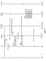
- FIG. 1 depicts a schematic protocol stack of the schematic LTE system without a load balancer.
- the traffic from the core network and the RAP is directly sent to the UE CP/UP VNFC.
- UE related CP or UP functionality closely engage with a core network, RAPs and cell specific or central control plane logic etc. There are exposed interfaces between each of these “partners” and UE VNFC.
- the present disclosure proposes a solution for load balancing in the C-RAN. It may overcome at least one of the drawbacks mentioned above or other drawbacks. It is noted that though the embodiments are mainly described in the context of the LTE system, they are not limited to this but can be applied to any suitable wireless system. Now some exemplary embodiments of the present disclosure will be described below with reference to the figures.
- FIG. 3 depicts a schematic system 300 , in which some embodiments of the present disclosure can be implemented.
- the system 300 comprises a C-RAN 310 .
- the C-RAN 310 may refer to a function element on the network side as compared to a terminal device or UE.
- the C-RAN 310 may be capable to serve terminal devices such as UEs in the system 300 .
- the C-RAN 310 may comprise load balancers 302 and 304 which can receive user plane (UP) data or control plane (CP) data associated with a user from a core network 306 or a remote access point 302 , 304 , 306 , 308 and dispatch the UP data or CP data to a UE VNFC 312 based on a route which may be created based on a load of one or more UE-VNFCs. It is noted that there may be two or more UE VNFCs though only one UE VNFC 312 is shown in FIG. 3 .
- the load balancers 302 and 304 can be a single apparatus though they are depicted as two separate apparatus. The load balancers can be located at an edge of C-RAN.
- the load balancers can exist as one or more VNFCs or as a middle ware of the C-RAN 310 .
- Load Balancer provides interface to the core network and remote antenna access units.
- Load Balancer receives c-plane and u-plane traffic from C-RAN outside and dispatch traffic into VNFCs.
- the load balancer or components thereof can be located in the core network or RAP.
- the dispatching functionality of the load balancer may be implemented by a software defined networking (SDN) traffic forwarding element such as vSwitch which will be described in detail hereinafter.
- the vSwitch may be located in the core network or RAP.
- FIG. 4 depicts a schematic load balancer according to an embodiment of the present disclosure.
- the load balancer 400 comprises a load balancer manager (LB-mgr) 402 which can provide any suitable management functionality.
- LB-mgr 402 can provide management-plane interface to outside for counters or faults etc.; be responsible to watch the health of the load balancer 400 's other components and reset an unhealthy component; read the customer metrics from a database (DB) 410 to watch the load information of the VNFCs; and create a promotion list or update it if such promotion list already exists.
- DB database
- the load balancer 400 further comprises a load balancer control plane (LB-c) 402 which can provide any suitable functionality associated with the control plane.
- LB-c 406 can act as a messaging communication point for application business logic; based on a promotion list, selects a VNFC to use; keep a session; create routes for traffic dispatch; and save user context into a DB 508 .
- the promotion list may be a list of VNFC loads that are listed in ascending or descending order.
- LB-c 402 can have horizontal scaling depending on traffic throughput load.
- the load balancer 400 further comprises a load balancer user plane (LB-u) 404 which can provide any suitable functionality associated with the user plane.
- LB-u 404 can dispatch u-plane traffic from RAP or the core network to a correct VNFC, based on the route created by the LB-c 406 and perform deep packet inspection to identify which user owns the packet.
- LB-u 404 can be implemented by a SDN vSwitch.
- LB-u 404 can have horizontal scaling depending on traffic throughput load.
- the load balancer 400 further comprises a session DB 408 which may be used to store user static and dynamic contexts information, also the routes information of traffic dispatch and a time-series DB 410 which may be used to store customer metrics of load such as load information of UE VNFCs and LB-u 404 .
- the session DB 408 and the time-series DB 410 can be separate DBs or can be integrated together.
- the session DB 408 and the time-series DB 410 can be implemented by using any suitable DB technology such as Influx DB or Redis DB.
- the C-RAN 310 may further comprise one or more UE-VNFCs 312 , 314 , 316 , 318 .
- the UE-VNFCs 312 , 314 , 316 , 318 may provide any suitable functionality associated with UE CP and/or UE UP.
- the UE-VNFC 312 may provide functionality associated with both UE CP and UE UP
- the UE-VNFC 314 may provide functionality associated with UE CP or UE UP, or the like.
- the UE-VNFCs 312 , 314 , 316 , 318 may be implemented by a virtual machine and run with any kind of operating system including, but not limited to, Windows, Linux, UNIX, iOS and their variants.
- the C-RAN 310 may further comprise a cell VNFC 320 which may serve at least one RAP. It is noted that there may be a plurality of cell VNFCs 320 each of which serves different RAPs though only one cell VNFC 320 is shown in FIG. 3 .
- the C-RAN 310 may further comprise a centralized control plane (CCP) VNFC 322 which may provide functionality associated with the control plane of the C-RAN 310 ; and an operation and maintenance (OAM) VNFC 324 which may provide functionality associated with the OAM of the C-RAN 310 .
- CCP centralized control plane
- OAM operation and maintenance
- the C-RAN 310 may further comprise any other suitable components.
- the system 300 further comprise one or more RAPs 302 , 304 , 306 , 308 .
- a cellular radio system may comprise a network of radio cells each served by the RAP, known as a cell site or base transceiver station.
- the radio network provides wireless communications service for a plurality of more transceivers (in most cases mobile).
- the network of RAPs working in collaboration allows for wireless service which is greater than the radio coverage provided by a single RAP.
- the individual RAP may be connected to the C-RAN through a transmission equipment 340 , such as optical transmission device or microwave equipment.
- the system 300 further comprise a core network 306 which is a telecommunication network's core part and offers numerous services to the customers who are interconnected by the RAP.
- the core network 306 may comprise Home Subscriber Server (HSS) component, a Packet Data Network (PDN) Gateway (P-GW), a serving gateway (S-GW), a mobility management entity (MME), a Policy Control and Charging Rules Function (PCRF), etc.
- HSS Home Subscriber Server
- PDN Packet Data Network
- S-GW serving gateway
- MME mobility management entity
- PCRF Policy Control and Charging Rules Function
- FIG. 5 depicts a schematic protocol stack of a LTE system with a load balancer according to an embodiment of the present disclosure.
- the traffic from the core network and the RAP is first sent to the load balancers 502 , 504 , 506 which may dispatch the traffic to a UE VNFC based on a route, wherein the route may be created based on a load of the one or more UE-VNFCs of the C-RAN.
- the load balancers 502 , 504 , 506 user migrations among UE VNFCs become the load balancer's internal logic, as the load balancer hides user's external connectivity, no tangles with RAP or core network during migration.
- the load balancer may make on-demand scaling of UE VNFCs be seamless, the UE VNFCs' scale-out or scale-in are scoped inside the load balancer, no impact to outside RAP or core network etc.
- the load balancer may facilitate UE VNFCs' high availability (N+M) as well.
- the load balancer can define an order to do UE VNFCs' rolling upgrade/fallback, without business service downtime.
- the load balancer may further support a concept of incremental software delivery. With the load balancer, UE service gets different dimensions to trigger on-demand scaling, for example, traffic load, signaling load and active user numbers etc., each map to a different VNFC.
- the load balancer may benefit compact resource requirement and usage of C-RAN.
- FIGS. 6A and 6B are flow charts depicting methods according to an embodiment of the present disclosure, which may be performed at an apparatus such as the load balancer as shown in FIGS. 3-5 .
- the apparatus may provide unit for accomplishing various parts of the methods 600 A and 600 B as well as unit for accomplishing other processes in conjunction with other components.
- the method 600 A may start at block 602 A where the load balancer receives CP data associated with a user from the core network or the RAP.
- the method 600 B may start at block 602 B where the load balancer receives UP data associated with a user from the core network or the RAP.
- an application may create data packets that are processed by protocols such as TCP, UDP and IP, while in the control plane, signaling messages are exchanged between the core network, C-RAN and the UE.
- the information may be processed by packet data convergence protocol (PDCP), radio link control (RLC) protocol and medium access control (MAC) protocol, before being passed to the physical layer for transmission.
- PDCP packet data convergence protocol
- RLC radio link control
- MAC medium access control
- the user plane protocol stack between the eNodeB and UE may comprise the following sub-layers: PDCP, RLC and MAC.
- packets in the core network such as EPC (Evolved Packet Core)
- EPC Evolved Packet Core
- packets in the core network are encapsulated in a specific EPC protocol and tunneled between the P-GW and the eNodeB.
- Different tunneling protocols are used depending on the interface.
- GTP GPRS Tunneling Protocol
- the control plane handles radio-specific functionality.
- the core network such as MME may provide the control plane function for mobility.
- the load balancer may receive only CP data, only UP data or both CP data and UP data associated with the user.
- the load balancer dispatches the CP data to a first UE VNFC based on a first route.
- the load balancer dispatches the UP data to a second UE-VNFC based on a second route.
- the load balancer may generate the route based on a route policy defined by a network administrator for example.
- the route policy may include a mechanism for selectively applying policies based on access list, user priority, QoS (quality of service), data size, data type, UE VNFC load or other criteria. For example, if the data type is CP data, then the route for the CP data is to the UE CP VNFC.
- the route for the UP data is to the UE UP VNFC.
- the route for the data from/to the user may be to the UE VNFC with higher availability.
- the first UE-VNFC may be same as or different from the second UE-VNFC. For example, if the first UE VNFC processes only the CP data and the second UE-VNFC processes only the UP data, then the first UE-VNFC may be different from the second UE-VNFC. In another example, if a UE-VNFC can process both the CP data and the UP data, then the first UE-VNFC and the second UE-VNFC may be the same UE-VNFC.
- the route is created based on a load of the one or more UE-VNFCs. For example, if there is not a route for the received UP data or CP data, the load balancer may generate the route to the UE VNFC with lowest current load for the received UP data or CP data.
- the dispatching functionality of the load balancer may be implemented by a software defined networking (SDN) traffic forwarding element such as vSwitch.
- SDN software defined networking
- FIG. 13 depicts a schematic system, in which the dispatching functionality of the load balancer is implemented by the SDN vSwitch. As shown in FIG.
- LB-c 1310 tells routing rules to a SDN controller 1312 through a SDN northbound interface (NBI), which configures a flow table to vSwitch 1318 , then for incoming traffic, vSwitch 1318 may dispatch them to correct UE VNFCs directly. There may be no extra hop and no extra delay any more.
- the traffic may be IPSec (IP Security) decrypted before dispatched by the vSwitch 1318 . It is noted that there may be a plurality of vSwitchs 1318 each of which may serve at least one RAP.
- FIG. 7 is a flow chart depicting a method 700 according to an embodiment of the present disclosure, which may be performed at an apparatus such as the load balancer as shown in FIGS. 3-5 .
- the apparatus may provide unit for accomplishing various parts of the method 700 as well as unit for accomplishing other processes in conjunction with other components.
- the load balancer collects load information of the one or more UE-VNFCs.
- the load balancer may periodically collect load information of the one or more UE-VNFCs.
- the one or more UE-VNFCs may report their load information to the load balancer periodically or based on a predefined event, such as the changed load information or in response to a request for the load information.
- the load balancer create or update a promotion list based on the load information.
- the promotion list may be a list of VNFC loads that are listed in ascending/descending order.
- the load balancer performs load balancing based on the promotion list.
- the route may be created based on the promotion list.
- the load balancer may select the UE VNFC with the lowest load from the promotion list and generate the route to the selected UE VNFC for the received UP data or CP data.
- the load balancer may save the user's context information which comprises static context information and CP context information.
- the user's static context may be created or modified during user/bearer setup and may comprise user ID, UE ID, service type, etc.
- the dynamic context be created or updated during per packet processing and may comprise PDCP sequence number, RLC buffers, etc.
- LB-c of the load balancer may store static context of this user into the session database, and the UE VNFC may update the user's dynamic context into the same session database.
- SRB signalaling radio bearers
- DRB data radio bearers
- the load balancer may perform deep packet inspection (DPI).
- DPI can examine the data part of a packet as it passes the load balancer, searching for protocol non-compliance, viruses, spam, intrusions, or defined criteria to decide whether the packet may pass or if it needs to be routed to a different destination, or for the purpose of collecting statistical information.
- DPI may be used to identify which user owns the packet.
- FIG. 8 is a flow chart depicting a method for user migration according to an embodiment of the present disclosure, which may be performed at an apparatus such as the load balancer as shown in FIGS. 3-5 .
- the apparatus may provide unit for accomplishing various parts of the method 800 as well as unit for accomplishing other processes in conjunction with other components.
- the load balancer can migrate a user from a source UE VNFC to a target UE VNFC.
- the load balancer sends a migration request for the user to a target UE VNFC such that the target UE VNFC fetches the user's context information.
- the migration request may comprise any suitable information such as the address of the source UE VNFC.
- the target UE VNFC may fetch the user's static context information from the session database of the load balance and fetch the user's dynamic context information from the source UE VNFC.
- the load balancer may trigger the user's context information forwarding to the target UE VNFC.
- the load balancer updates the route of the UP data and/or CP data associated with the user to the target UE VNFC. For example, if the source UE VNFC processes only the UP data associated with the user, then the load balancer updates the route of the UP data associated with the user to the target UE VNFC; if the source UE VNFC processes only the CP data associated with the user, then the load balancer updates the route of the CP data associated with the user to the target UE VNFC; and if the source UE VNFC processes both the UP data and the CP data associated with the user, then the load balancer updates the route of both the UP data and the CP data associated with the user to the target UE VNFC.
- the load balancer receives a migration finish message from the target UE VNFC. For example, when the target UE VNFC restores the user's context information and continues processing the UP data and/or CP data associated with the user, the target UE VNFC may send the migration finish message to the load balancer.
- the load balancer notifies the source UE VNFC that the user can be deleted from the source UE VNFC.
- FIG. 9 is a flow chart depicting a method for user migration according to an embodiment of the present disclosure.
- LB-c makes a user migration decision due to various reasons, for example load balancing, maintenance, upgrade, saving power consumption, etc.
- LB-c reads the user's context information from the session DB and sends a user migration request to a target UE VNFC. Or alternative, if there are multiple users to be migrated, LB-c can distribute user identities among new target UE VNFCs based on load situation, and tells each UE VNFC which indexes they shall access in the session database, so that the target UE VNFCs restore UE context information by themselves in parallel.
- the target UE VNFC may fetch the user's static context from the session database and setup the user.
- LB-c updates the traffic dispatch route, so that new incoming traffic may go to the target UE VNFC.
- LB-c sends message to the source UE VNFC for triggering RLC layer data/context forwarding from the source UE VNFC to the target UE VNFC.
- the source UE VNFC may perform in-band PDCP/RLC context forwarding. Then the target UE VNFC may restore the user's dynamic context and continue processing the user-plane data.
- the target UE VNFC may send a user migration finish information to LB-c at 914 .
- LB-c may send a user deletion request to the source UE VNFC which may delete the user.
- the user migration procedure happens inside the scope of load balancer, it has no impacts to outside RAP or core network, as from their perspectives, the communication addresses are unchanged, which are still the address of the load balancer. So, user live migration's impacts are limited inside the scope of load balancer and are self-contained.
- FIG. 10 is a flow chart depicting a method for providing high availability according to an embodiment of the present disclosure, which may be performed at an apparatus such as the load balancer as shown in FIGS. 3-5 .
- the apparatus may provide unit for accomplishing various parts of the method 1000 as well as unit for accomplishing other processes in conjunction with other components.
- the load balancer can guarantee high availability in case of a UE VNFC crashed.
- the load balancer detects that the a UE VNFC is crashed.
- the load balancer may detect that the UE VNFC is crashed in various ways. For example, the load balancer may periodically monitoring the health of the UE VNFCs.
- the UE VNFC may send a heartbeat message to the load balancer at a predefined time, and if the load balancer can not receive the heartbeat message from the UE VNFC at the predefined time, then the load balancer may detect that the UE VNFC is crashed.
- the load balancer sends, for at least one user impacted by the crashed UE VNFC, a user restore request to at least one new UE VNFC such that the at least one new UE VNFC fetches the at least one user's context information.
- the at least one new UE VNFC may fetch the at least one user's context information from the session DB.
- the load balancer may send a RRC command to respective UEs of the at least one user such that the respective UEs re-syncs respective UP context information with the at least one new UE UP VNFC.
- the load balancer updates the route of the UP data and/or CP data associated with the impacted at least one user to the at least one new UE VNFC. For example, if the crashed UE VNFC previously processed only the UP data associated with the impacted at least one user, then the load balancer updates the route of the UP data associated with the impacted at least one user to the at least one new UE VNFC; if the crashed UE VNFC previously processed only the CP data associated with the impacted at least one user, then the load balancer updates the route of the CP data associated with the impacted at least one user to the at least one new UE VNFC; and if the crashed UE VNFC previously processed both the UP data and the CP data associated with the impacted at least one user, then the load balancer updates the route of both the UP data and the CP data associated with the impacted at least one user to the at least one new UE VNFC.
- the load balancer receives a user restore finish message from the at least one new UE VNFC.
- FIG. 11 is a flow chart depicting a process for providing high availability according to an embodiment of the present disclosure.
- LB-c observes that a UE UP VM is crashed.
- LB-c reads, from session DB, user context information for at least one user impacted by the crashed UE VNFC and sends, for the impacted at least one user, a user restore request to at least one new UE UP VNFC.
- LB-c can distribute user identities among multiple new UE UP VNFCs based on load situation, LB-c tells each UE UP VNFC which indexes it shall access in the session database, so that target UE VNFCs come to restore multiple user context information by themselves in parallel.
- Dynamic user context information of user SRB bears may be stored in the session database, or even further, SRB bears' RLC/PDCP processing are processed on a separated non-crashed UE CP VNFC, so that user's SRBs can be fully recovered or still alive during UE UP VNFC crash.
- the new UE UP VM fetch the user static context of the impacted at least one user from the session database and setup the impacted at least one user.
- LB-c updates the u-plane traffic dispatch routes for the impacted at least one user, so new incoming traffic may go to the new UE VNFC.
- LB-c tells the UE CP VNFC to perform RRC command towards UEs to re-sync the PDCP/RLC state with the new UE UP VNFC for DRB by intra cell handover for example.
- the new UE UP VNFC learns new PDCP/RLC context and continue process the user plane data. Then the new UE UP VNFC may send a user restore finish information to LB-c at 1114 .
- the u-plane high availability procedure might be visible to mobile phone/UE, but without impacts to outside RAP or core network, as from their perspectives, the communication addresses are unchanged, which are still load balancer's address.
- FIG. 12 depicts an apparatus capable of load balancing in C-RAN as described above, wherein the apparatus may be implemented by or included in the load balancer.
- the apparatus 1200 comprises a processing device 1204 , a memory 1205 , and a transceiver 1201 in operative communication with the processor 1204 .
- the transceiver 1201 comprises at least one transmitter 1202 and at least one receiver 1203 .
- the processing device 1204 may comprises one or more processors or multi-core processor(s). Additionally, the processing device 1204 may also comprise cache to facilitate processing operations.
- Computer-executable instructions can be loaded in the memory 1205 and, when executed by the processing device 1204 , cause the apparatus 1200 to implement the above-described methods for load balancing in C-RAN.
- the computer-executable instructions can cause the apparatus 1200 to receive control plane (CP) data associated with a user from a core network or a remote access point; and dispatch the CP data to a first user equipment (UE) virtualized network function component (VNFC) based on a first route.
- CP control plane
- UE user equipment
- VNFC virtualized network function component
- the apparatus 1200 is further configured to receive user plane (UP) data associated with the user from the core network or the remote access point; and dispatch the UP data to a second UE-VNFC based on a second route, wherein the first UE-VNFC is same as or different from the second UE-VNFC.
- UP user plane
- the apparatus 1200 is further configured to collect load information of the one or more UE-VNFCs; create or update a promotion list based on the load information; and perform load balancing based on the promotion list.
- the apparatus 1200 is further configured to save the user's context information which comprises static context information and dynamic context information.
- the apparatus 1200 is further configured to perform deep packet inspection.
- dispatching the CP data to a first UE-VNFC based on a first route comprises dispatching, by a software defined networking (SDN) traffic forwarding element, the CP data to the first UE VNFC based on the first route and dispatching the UP data to a second UE-VNFC based on a second route comprises dispatching, by the software defined networking (SDN) traffic forwarding element, the UP data to the second UE VNFC based on the second route.
- SDN software defined networking
- the apparatus 1200 is further configured to send a migration request for the user to a target UE VNFC such that the target UE VNFC fetches the user's context information; update the route of the UP data and/or CP data associated with the user to the target UE VNFC; receive a migration finish message from the target UE VNFC; and notify a source UE VNFC that the user can be deleted from the source UE VNFC.
- the apparatus 1200 is further configured to detect that the UE VNFC is crashed; send, for at least one user impacted by the crashed UE VNFC, a user restore request to at least one new UE VNFC such that the at least one new UE VNFC fetches the at least one user's context information; update the route of the UP data and/or CP data associated with the at least one user to the at least one new UE VNFC; and receive a user restore finish message from the new UE VNFC, wherein if the UE VNFC is a UE UP VNFC, the method further comprises causing respective UEs of the at least one user to re-sync respective UP context information of the at least one user with the at least one new UE UP VNFC.
- the route is created based on a load of the one or more UE-VNFCs.
- an apparatus capable of implementing the methods for load balancing in C-RAN as described above, wherein the apparatus may be implemented by or included in the load balancer.
- the apparatus comprises a receiving unit for receiving control plane (CP) data associated with a user from a core network or a remote access point; and a dispatching unit for dispatching the CP data to a first user equipment (UE) virtualized network function component (VNFC) based on a first route.
- CP control plane
- UE user equipment
- VNFC virtualized network function component
- the apparatus further comprises a receiving unit for receiving user plane (UP) data associated with the user from the core network or the remote access point; and a dispatching unit for dispatching the UP data to a second UE-VNFC based on a second route, wherein the first UE-VNFC is same as or different from the second UE-VNFC.
- UP user plane
- the apparatus further comprises a collecting unit for collecting load information of the one or more UE-VNFCs; a creating/updating unit for creating or updating a promotion list based on the load information; and a performing unit for performing load balancing based on the promotion list.
- the apparatus further comprises a saving unit for saving the user's context information which comprises static context information and dynamic context information.
- the apparatus further comprises a performing unit for performing deep packet inspection.
- the dispatching unit is implement by a software defined networking (SDN) traffic forwarding element.
- SDN software defined networking
- the apparatus further comprises a sending unit for sending a migration request for the user to a target UE VNFC such that the target UE VNFC fetches the user's context information; an updating unit for updating the route of the UP data and/or CP data associated with the user to the target UE VNFC; a receiving unit for receiving a migration finish message from the target UE VNFC; and a notifying unit for notifying the UE VNFC that the user can be deleted from the UE VNFC.
- the apparatus further comprise a detecting unit for detecting that the UE VNFC is crashed; a sending unit for sending, for at least one user impacted by the crashed UE VNFC, a user restore request to at least one new UE VNFC such that the at least one new UE VNFC fetches the at least one user's context information; an updating unit for updating the route of the UP data and/or CP data associated with the at least one user to the at least one new UE VNFC; and a receiving unit for receiving a user restore finish message from the new UE VNFC, wherein if the UE VNFC is a UE UP VNFC, respective UEs of the at least one user is caused to re-sync respective UP context information of the at least one user with the at least one new UE UP VNFC.
- the route is created based on a load of the one or more UE-VNFCs.
- a computer program product comprising at least one non-transitory computer-readable storage medium having computer-executable program instructions stored therein, the computer-executable instructions being configured to, when being executed, cause an apparatus to operate as described above.
- a computer readable storage medium comprising instructions which when executed by at least one processor, cause the at least one processor to perform the method as described above.
- the embodiments of the disclosure may have the following advantages.
- load balancer LB
- user migrations among UE VNFCs become UE service's internal logic, as LB takes and hides user's external connectivity, no tangles with RAP or core network during migration. Thanks to hiding and user migration, LB makes on-demand scaling of UE VNFCs be seamless, the UE VNFCs' scale-out or scale-in are scoped inside LB, no impact to outside RAP or core network etc.
- LB facilitates UE VNFCs' high availability (N+M) as well.
- LB can define the order to do UE VNFCs' rolling upgrade/fallback, without business service downtime. It further supports the concept of incremental software delivery.
- UE service gets different dimensions to trigger on-demand scaling, for example, traffic load, signaling load and active user numbers etc., each map to a different VNFC. It benefits compact resource requirement and usage of VNF.
- LB may be a new VNFC, can be deployed in VMs or containers. Load balancer as a common service, loose-coupled with application business logic, can be used for different C-RAN products. LB can use either software defined dispatcher, or SDN vSwitch to dispatch traffic. LB creates a UE service-oriental RAN software, with limited changes to original software, facilitate original software to get such as self-contained, self-scaling, self-healing and self-configured cloud native characteristics. LB facilitates RAN as a service.
- any of the components of load balancer can be implemented as hardware or software modules.
- software modules they can be embodied on a tangible computer-readable recordable storage medium. All of the software modules (or any subset thereof) can be on the same medium, or each can be on a different medium, for example.
- the software modules can run, for example, on a hardware processor. The method steps can then be carried out using the distinct software modules, as described above, executing on a hardware processor.
- program means to include any sequences or human or machine cognizable steps which perform a function.
- Such program may be rendered in virtually any programming language or environment including, for example, C/C++, Fortran, COBOL, PASCAL, assembly language, markup languages (e.g., HTML, SGML, XML), and the like, as well as object-oriented environments such as the Common Object Request Broker Architecture (CORBA), JavaTM (including J2ME, Java Beans, etc.), Binary Runtime Environment (BREW), and the like.
- CORBA Common Object Request Broker Architecture
- JavaTM including J2ME, Java Beans, etc.
- BREW Binary Runtime Environment
- memory and “storage device” are meant to include, but not limited to, an electronic, magnetic, optical, electromagnetic, infrared, or semiconductor system, apparatus, or device, or any suitable combination of the foregoing. More specific examples (a non-exhaustive list) of the memory or storage device would include the following: an electrical connection having one or more wires, a portable computer diskette, a hard disk, a random access memory (RAM), a read-only memory (ROM), an erasable programmable read-only memory (EPROM or Flash memory), an optical fiber, a portable compact disc read-only memory (CD-ROM), an optical storage device, a magnetic storage device, or any suitable combination of the foregoing.
- RAM random access memory
- ROM read-only memory
- EPROM or Flash memory erasable programmable read-only memory
- CD-ROM compact disc read-only memory
- magnetic storage device or any suitable combination of the foregoing.
Abstract
Description
Claims (16)
Applications Claiming Priority (1)
| Application Number | Priority Date | Filing Date | Title |
|---|---|---|---|
| PCT/CN2017/117512 WO2019119305A1 (en) | 2017-12-20 | 2017-12-20 | Method and apparatus for load balancing in a cloud-radio access network |
Publications (2)
| Publication Number | Publication Date |
|---|---|
| US20210185563A1 US20210185563A1 (en) | 2021-06-17 |
| US11510103B2 true US11510103B2 (en) | 2022-11-22 |
Family
ID=66992901
Family Applications (2)
| Application Number | Title | Priority Date | Filing Date |
|---|---|---|---|
| US16/769,637 Active US11510103B2 (en) | 2017-12-20 | 2017-12-20 | Method and apparatus for load balancing in a Cloud-radio access network |
| US16/954,614 Active US11558780B2 (en) | 2017-12-20 | 2018-09-07 | Method and apparatus for user transfer in a cloud-radio access network |
Family Applications After (1)
| Application Number | Title | Priority Date | Filing Date |
|---|---|---|---|
| US16/954,614 Active US11558780B2 (en) | 2017-12-20 | 2018-09-07 | Method and apparatus for user transfer in a cloud-radio access network |
Country Status (5)
| Country | Link |
|---|---|
| US (2) | US11510103B2 (en) |
| EP (2) | EP3729864A4 (en) |
| JP (2) | JP7153074B2 (en) |
| CN (2) | CN111557109B (en) |
| WO (2) | WO2019119305A1 (en) |
Families Citing this family (3)
| Publication number | Priority date | Publication date | Assignee | Title |
|---|---|---|---|---|
| CN113905449B (en) * | 2021-09-30 | 2024-04-05 | 杭州阿里云飞天信息技术有限公司 | Computing resource scheduling method, system and equipment |
| CN116074791A (en) * | 2021-10-30 | 2023-05-05 | 华为技术有限公司 | Service transfer method and communication device |
| CN116669108A (en) * | 2022-02-18 | 2023-08-29 | 中兴通讯股份有限公司 | Message sending method, message sending device and storage medium |
Citations (18)
| Publication number | Priority date | Publication date | Assignee | Title |
|---|---|---|---|---|
| US20140269322A1 (en) * | 2012-02-24 | 2014-09-18 | Guangjie Li | Cooperative radio access network with centralized base station baseband unit (bbu) processing pool |
| US20150124622A1 (en) | 2013-11-01 | 2015-05-07 | Movik Networks, Inc. | Multi-Interface, Multi-Layer State-full Load Balancer For RAN-Analytics Deployments In Multi-Chassis, Cloud And Virtual Server Environments |
| CN105516312A (en) | 2015-12-09 | 2016-04-20 | 重庆邮电大学 | Software defined networking load balancingdevice and method |
| CN105681216A (en) | 2016-04-27 | 2016-06-15 | 赛特斯信息科技股份有限公司 | System and method for network service access control and load balance under NFV (network functions virtualization) architecture |
| US20160205518A1 (en) | 2015-01-14 | 2016-07-14 | Kodiak Networks Inc. | System and Method for Elastic Scaling using a Container-Based Platform |
| JP2016532403A (en) | 2013-09-12 | 2016-10-13 | アルカテル−ルーセント | Scheduling virtualization on mobile cloud for low latency backhaul |
| US20160366009A1 (en) | 2015-06-09 | 2016-12-15 | Nokia Solutions And Networks Oy | Methods and Apparatus for Radio Access Network Resource Management |
| US20160381662A1 (en) * | 2015-06-29 | 2016-12-29 | At&T Intellectual Property I, Lp | Mobility Network Function Consolidation |
| US20170086049A1 (en) * | 2015-09-18 | 2017-03-23 | Huawei Technologies Co., Ltd. | System and methods for reliable communication with mobility along a predictable route |
| US20170104609A1 (en) | 2015-10-09 | 2017-04-13 | Openet Telecom Ltd. | System and Method for Enabling Service Lifecycle Based Policy, Licensing, and Charging in a Network Function Virtualization Ecosystem |
| US20170111274A1 (en) | 2014-10-30 | 2017-04-20 | Brocade Communications Systems, Inc. | Distributed customer premises equipment |
| US20170116019A1 (en) | 2015-10-22 | 2017-04-27 | Genband Us Llc | Network Management for Elastic Virtual Network Functions |
| US20170134483A1 (en) | 2015-11-06 | 2017-05-11 | Genband Us Llc | Independent Groups of Virtual Network Function Components |
| CN106851738A (en) | 2017-01-25 | 2017-06-13 | 南京邮电大学 | Towards the software definition wireless network architecture and method of the small base station super-intensive networkings of LTE |
| CN106937331A (en) | 2015-12-31 | 2017-07-07 | 大唐移动通信设备有限公司 | A kind of baseband processing method and device |
| CN106963201A (en) | 2017-05-23 | 2017-07-21 | 浙江瑞轩健康科技有限公司 | A kind of improved pillow cover and its action method |
| US20170272380A1 (en) | 2016-03-17 | 2017-09-21 | Huawei Technologies Co., Ltd. | Virtual Network Function State Scaling |
| US20170272523A1 (en) | 2016-03-21 | 2017-09-21 | International Business Machines Corporation | Replacing a virtual network function in a network service |
Family Cites Families (22)
| Publication number | Priority date | Publication date | Assignee | Title |
|---|---|---|---|---|
| AU2006309464B2 (en) * | 2005-10-31 | 2009-10-29 | Lg Electronics Inc. | Method for processing control information in a wireless mobile communication system |
| US8879500B2 (en) * | 2006-03-21 | 2014-11-04 | Qualcomm Incorporated | Handover procedures in a wireless communications system |
| US8451795B2 (en) | 2007-08-08 | 2013-05-28 | Qualcomm Incorporated | Handover in a wireless data packet communication system that avoid user data loss |
| EP2498540B1 (en) * | 2011-03-11 | 2013-03-06 | Alcatel Lucent | Computing cloud in a wireless telecommunication system |
| WO2015133126A1 (en) | 2014-03-04 | 2015-09-11 | 日本電気株式会社 | Server, control device, management device, communication system, communication method, control method, management method, and program |
| US20170017510A1 (en) * | 2014-03-04 | 2017-01-19 | Nec Corporation | Server, control apparatus, management apparatus, communication system, communication method, control method, management method, and program |
| JPWO2015133125A1 (en) | 2014-03-04 | 2017-04-06 | 日本電気株式会社 | Server, control device, management device, communication system, communication method, control method, management method, and program |
| US11294698B2 (en) | 2014-03-10 | 2022-04-05 | Nokia Solutions And Networks Oy | Waiting a host determined specific amount of time before performing virtual network function migration |
| CN104951352B (en) | 2014-03-31 | 2018-05-11 | 华为技术有限公司 | The moving method and equipment of a kind of data flow |
| US10292192B2 (en) * | 2014-05-06 | 2019-05-14 | Lg Electronics Inc. | Method for processing received RLC PDUs for D2D communication system and device therefor |
| WO2015170433A1 (en) * | 2014-05-07 | 2015-11-12 | 日本電気株式会社 | Communication system, base station, communication method, and nontemporary computer readable medium on which program has been stored |
| WO2016050288A1 (en) | 2014-10-01 | 2016-04-07 | Nokia Solutions And Networks Oy | Session transfer by tunnel endpoint identifier renumbering |
| WO2016070302A1 (en) | 2014-11-03 | 2016-05-12 | 华为技术有限公司 | Virtual network function example migration method, device and system |
| EP3247148B1 (en) * | 2015-02-09 | 2019-05-15 | Huawei Technologies Co., Ltd. | Rlc data packet offloading method, and base station |
| US9775045B2 (en) | 2015-09-11 | 2017-09-26 | Intel IP Corporation | Slicing architecture for wireless communication |
| US9930587B2 (en) | 2015-09-18 | 2018-03-27 | Huawei Technologies Co., Ltd. | Distributed virtual gateways |
| CN105407057B (en) * | 2015-12-07 | 2018-09-25 | 中国联合网络通信集团有限公司 | A kind of method and device of load balancing |
| US10420134B2 (en) * | 2016-02-02 | 2019-09-17 | Cisco Technology, Inc. | System and method to facilitate subframe scheduling in a split medium access control radio access network environment |
| WO2018099569A1 (en) | 2016-12-02 | 2018-06-07 | Telefonaktiebolaget Lm Ericsson (Publ) | Configuration control for network |
| EP3552350B1 (en) | 2016-12-06 | 2021-02-24 | Nokia Solutions and Networks Oy | Scalable mobile network |
| US10932168B2 (en) * | 2017-09-29 | 2021-02-23 | Apple Inc. | Next generation node-B (gNB) and methods for mobility management with separate user plane and control plane in new radio (NR) systems |
| US11265801B2 (en) * | 2017-11-17 | 2022-03-01 | Telefonaktiebolaget Lm Ericsson (Publ) | Information exchange for initial user equipment access |
-
2017
- 2017-12-20 CN CN201780097865.6A patent/CN111557109B/en active Active
- 2017-12-20 US US16/769,637 patent/US11510103B2/en active Active
- 2017-12-20 EP EP17935628.2A patent/EP3729864A4/en active Pending
- 2017-12-20 WO PCT/CN2017/117512 patent/WO2019119305A1/en unknown
- 2017-12-20 JP JP2020534553A patent/JP7153074B2/en active Active
-
2018
- 2018-09-07 WO PCT/CN2018/104641 patent/WO2019119882A1/en unknown
- 2018-09-07 US US16/954,614 patent/US11558780B2/en active Active
- 2018-09-07 CN CN201880089554.XA patent/CN111771356A/en active Pending
- 2018-09-07 EP EP18892589.5A patent/EP3729742A4/en active Pending
-
2022
- 2022-07-22 JP JP2022117389A patent/JP7382462B2/en active Active
Patent Citations (19)
| Publication number | Priority date | Publication date | Assignee | Title |
|---|---|---|---|---|
| CN105359574A (en) | 2012-02-24 | 2016-02-24 | 英特尔公司 | Cooperative radio access network with centralized base station baseband unit (BBU) processing pool |
| US20140269322A1 (en) * | 2012-02-24 | 2014-09-18 | Guangjie Li | Cooperative radio access network with centralized base station baseband unit (bbu) processing pool |
| JP2016532403A (en) | 2013-09-12 | 2016-10-13 | アルカテル−ルーセント | Scheduling virtualization on mobile cloud for low latency backhaul |
| US20150124622A1 (en) | 2013-11-01 | 2015-05-07 | Movik Networks, Inc. | Multi-Interface, Multi-Layer State-full Load Balancer For RAN-Analytics Deployments In Multi-Chassis, Cloud And Virtual Server Environments |
| US20170111274A1 (en) | 2014-10-30 | 2017-04-20 | Brocade Communications Systems, Inc. | Distributed customer premises equipment |
| US20160205518A1 (en) | 2015-01-14 | 2016-07-14 | Kodiak Networks Inc. | System and Method for Elastic Scaling using a Container-Based Platform |
| US20160366009A1 (en) | 2015-06-09 | 2016-12-15 | Nokia Solutions And Networks Oy | Methods and Apparatus for Radio Access Network Resource Management |
| US20160381662A1 (en) * | 2015-06-29 | 2016-12-29 | At&T Intellectual Property I, Lp | Mobility Network Function Consolidation |
| US20170086049A1 (en) * | 2015-09-18 | 2017-03-23 | Huawei Technologies Co., Ltd. | System and methods for reliable communication with mobility along a predictable route |
| US20170104609A1 (en) | 2015-10-09 | 2017-04-13 | Openet Telecom Ltd. | System and Method for Enabling Service Lifecycle Based Policy, Licensing, and Charging in a Network Function Virtualization Ecosystem |
| US20170116019A1 (en) | 2015-10-22 | 2017-04-27 | Genband Us Llc | Network Management for Elastic Virtual Network Functions |
| US20170134483A1 (en) | 2015-11-06 | 2017-05-11 | Genband Us Llc | Independent Groups of Virtual Network Function Components |
| CN105516312A (en) | 2015-12-09 | 2016-04-20 | 重庆邮电大学 | Software defined networking load balancingdevice and method |
| CN106937331A (en) | 2015-12-31 | 2017-07-07 | 大唐移动通信设备有限公司 | A kind of baseband processing method and device |
| US20170272380A1 (en) | 2016-03-17 | 2017-09-21 | Huawei Technologies Co., Ltd. | Virtual Network Function State Scaling |
| US20170272523A1 (en) | 2016-03-21 | 2017-09-21 | International Business Machines Corporation | Replacing a virtual network function in a network service |
| CN105681216A (en) | 2016-04-27 | 2016-06-15 | 赛特斯信息科技股份有限公司 | System and method for network service access control and load balance under NFV (network functions virtualization) architecture |
| CN106851738A (en) | 2017-01-25 | 2017-06-13 | 南京邮电大学 | Towards the software definition wireless network architecture and method of the small base station super-intensive networkings of LTE |
| CN106963201A (en) | 2017-05-23 | 2017-07-21 | 浙江瑞轩健康科技有限公司 | A kind of improved pillow cover and its action method |
Non-Patent Citations (7)
| Title |
|---|
| "Network Function Virtualisation; Use Cases;;GS-NFV-009v012-clean - Use Cases - Editorial comments", ETSI DRAFT; GS-NFV-009V012-CLEAN - USE CASES - EDITORIAL COMMENTS, EUROPEAN TELECOMMUNICATIONS STANDARDS INSTITUTE (ETSI), 650, ROUTE DES LUCIOLES ; F-06921 SOPHIA-ANTIPOLIS ; FRANCE, vol. ISG, no. V012, GS-NFV-009v012-clean - Use Cases - Editorial comme, 3 September 2013 (2013-09-03), 650, route des Lucioles ; F-06921 Sophia-Antipolis ; France , pages 1 - 54, XP014159597 |
| "Network Function Virtualisation; Use Cases;|GS-NFV-O09v012-clean—Use Cases—Editorial comments", ETSI Draft; GS-NFV-009V012-CLEAN—Use Cases—Editorial C0mments, Eur0pean Telec0mmunications Standards Institute (ETSI), 650, R0ute Des Luci0les ; F-06921 Sophia-Antipolis ; France,vol. ISG, No. V012,Sep. 3, 2013 (Sep. 3, 2013), pp. 1-54, XP014159597, [retrieved on Sep. 3, 2013]* Section 9. Use Case #5: Virtualisation of Mobile base Station; p. 31-p. 34 *. |
| D. KING LANCASTER UNIVERSITY M. LIEBSCH P. WILLIS J. RYOO ETRI: "Virtualisation of Mobile Core Network Use Case; draft-king-vnfpool-mobile-use-case-01.txt", VIRTUALISATION OF MOBILE CORE NETWORK USE CASE; DRAFT-KING-VNFPOOL-MOBILE-USE-CASE-01.TXT, INTERNET ENGINEERING TASK FORCE, IETF; STANDARDWORKINGDRAFT, INTERNET SOCIETY (ISOC) 4, RUE DES FALAISES CH- 1205 GENEVA, SWITZERLAND, draft-king-vnfpool-mobile-use-case-01, 8 June 2014 (2014-06-08), Internet Society (ISOC) 4, rue des Falaises CH- 1205 Geneva, Switzerland , pages 1 - 14, XP015099466 |
| ETSI Annex A (normative): NFV ISG PoC Proposal Template, 2014, 6 pgs. |
| ETSI GS NFV-SWA 001 V1.1.1 (Dec. 2014), Network Functions Virtualisation (NFV); Virtual Network Functions Architecture, 93 pgs. |
| King Lancaster University M Liebsch P Willis J Ryoo Etri D: "Virtualisation of Mobile Core Network Use Case;draft-king-vnfpool-mobile-use-case-01.txt" Virtualisation of Mobile Core Network Use Case; DRAFT-KING-VNFPOOL-MOBILE-USE-CASE-01.TXT, Internet Engineering Task Force, IETF; Standard Workingdraft, Internet Society (ISOC) 4, Rue Des Falaises CH—1205 Geneva, Switzerland, Jun. 8, 2014 (Jun. 8, 2014), pp. 1-14, XP015099466, [retrieved on Jun. 8, 2014]. |
| King Lancaster University—Virtualisation of Mobile Core Network Use Case, Jun. 8, 2014 (Year: 2014). * |
Also Published As
| Publication number | Publication date |
|---|---|
| EP3729864A4 (en) | 2021-07-28 |
| US20200314693A1 (en) | 2020-10-01 |
| JP2021507633A (en) | 2021-02-22 |
| US11558780B2 (en) | 2023-01-17 |
| JP2022166003A (en) | 2022-11-01 |
| JP7382462B2 (en) | 2023-11-16 |
| EP3729864A1 (en) | 2020-10-28 |
| CN111557109A (en) | 2020-08-18 |
| CN111771356A (en) | 2020-10-13 |
| JP7153074B2 (en) | 2022-10-13 |
| US20210185563A1 (en) | 2021-06-17 |
| WO2019119882A1 (en) | 2019-06-27 |
| WO2019119305A1 (en) | 2019-06-27 |
| EP3729742A1 (en) | 2020-10-28 |
| CN111557109B (en) | 2023-08-04 |
| EP3729742A4 (en) | 2021-09-22 |
Similar Documents
| Publication | Publication Date | Title |
|---|---|---|
| CN110169140B (en) | Method, device and system for releasing N2 connection associated with User Equipment (UE) | |
| US11451624B2 (en) | Virtual network manager system | |
| US11116029B2 (en) | Mobility management entity, network entity, and method and computer readable medium therefor | |
| JP7382462B2 (en) | Method and apparatus for load balancing in cloud radio access networks | |
| EP3337265B1 (en) | Apparatus and method related to dual connectivity | |
| CN109891829A (en) | SLA processing in network slice | |
| US10887931B2 (en) | Communication method and communications apparatus | |
| US10979888B2 (en) | Dynamic mobility network recovery system | |
| CN108713327A (en) | Network node for realizing the communication in communication network and the method that executes within network nodes | |
| US10489184B2 (en) | Systems and methods for management of virtual machine resources in a network environment through localized assignment of virtual machines having complimentary resource requirements | |
| US10620931B2 (en) | Automated device memory clean up mechanism | |
| US10305774B2 (en) | Enhanced U-verse / DSL internet services | |
| JP6233521B2 (en) | Base station, radio communication system and communication method | |
| US10491485B2 (en) | Expansive network control design system | |
| WO2015182255A1 (en) | Apparatus and method | |
| US10819591B2 (en) | Optical transport network design system | |
| US20230063162A1 (en) | OpenRAN Intelligent Dynamic CU-UP Scaling Solution | |
| US20230291646A1 (en) | SCTP Micro-Service High Availability in Public/Private Cloud | |
| CN117279031A (en) | Information processing method and communication device |
Legal Events
| Date | Code | Title | Description |
|---|---|---|---|
| FEPP | Fee payment procedure |
Free format text: ENTITY STATUS SET TO UNDISCOUNTED (ORIGINAL EVENT CODE: BIG.); ENTITY STATUS OF PATENT OWNER: LARGE ENTITY |
|
| AS | Assignment |
Owner name: NOKIA SHANGHAI BELL CO., LTD., CHINA Free format text: ASSIGNMENT OF ASSIGNORS INTEREST;ASSIGNORS:XU, LEI;KONG, TAO;XIE, BINGQUAN;AND OTHERS;SIGNING DATES FROM 20200618 TO 20200709;REEL/FRAME:053187/0188 Owner name: NOKIA SOLUTIONS AND NETOWRKS OY, FINLAND Free format text: ASSIGNMENT OF ASSIGNORS INTEREST;ASSIGNORS:XU, LEI;KONG, TAO;XIE, BINGQUAN;AND OTHERS;SIGNING DATES FROM 20200618 TO 20200709;REEL/FRAME:053187/0188 |
|
| AS | Assignment |
Owner name: NOKIA SHANGHAI BELL CO., LTD., CHINA Free format text: CORRECTIVE ASSIGNMENT TO CORRECT THE SECOND IDENTIFIED RECEIVING PARTY DATA (ASSIGNEE) PREVIOUSLY RECORDED ON REEL 053187 FRAME 0188. ASSIGNOR(S) HEREBY CONFIRMS THE ASSIGNMENT;ASSIGNORS:XU, LEI;KONG, TAO;XIE, BINGQUAN;AND OTHERS;SIGNING DATES FROM 20200618 TO 20200709;REEL/FRAME:053200/0515 Owner name: NOKIA SOLUTIONS AND NETWORKS OY, FINLAND Free format text: CORRECTIVE ASSIGNMENT TO CORRECT THE SECOND IDENTIFIED RECEIVING PARTY DATA (ASSIGNEE) PREVIOUSLY RECORDED ON REEL 053187 FRAME 0188. ASSIGNOR(S) HEREBY CONFIRMS THE ASSIGNMENT;ASSIGNORS:XU, LEI;KONG, TAO;XIE, BINGQUAN;AND OTHERS;SIGNING DATES FROM 20200618 TO 20200709;REEL/FRAME:053200/0515 |
|
| STPP | Information on status: patent application and granting procedure in general |
Free format text: DOCKETED NEW CASE - READY FOR EXAMINATION |
|
| STPP | Information on status: patent application and granting procedure in general |
Free format text: NON FINAL ACTION MAILED |
|
| STPP | Information on status: patent application and granting procedure in general |
Free format text: RESPONSE TO NON-FINAL OFFICE ACTION ENTERED AND FORWARDED TO EXAMINER |
|
| STPP | Information on status: patent application and granting procedure in general |
Free format text: NOTICE OF ALLOWANCE MAILED -- APPLICATION RECEIVED IN OFFICE OF PUBLICATIONS |
|
| STCF | Information on status: patent grant |
Free format text: PATENTED CASE |
|
| AS | Assignment |
Owner name: NOKIA SOLUTIONS AND NETWORKS OY, FINLAND Free format text: ASSIGNMENT OF ASSIGNORS INTEREST;ASSIGNORS:NOKIA SHANGHAI BELL CO., LTD.;NOKIA SOLUTIONS AND NETWORKS OY;SIGNING DATES FROM 20221031 TO 20221101;REEL/FRAME:061638/0591 |