WO2015133126A1 - Server, control device, management device, communication system, communication method, control method, management method, and program - Google Patents
Server, control device, management device, communication system, communication method, control method, management method, and program Download PDFInfo
- Publication number
- WO2015133126A1 WO2015133126A1 PCT/JP2015/001109 JP2015001109W WO2015133126A1 WO 2015133126 A1 WO2015133126 A1 WO 2015133126A1 JP 2015001109 W JP2015001109 W JP 2015001109W WO 2015133126 A1 WO2015133126 A1 WO 2015133126A1
- Authority
- WO
- WIPO (PCT)
- Prior art keywords
- signal
- vnf
- server
- tag information
- network
- Prior art date
Links
Images


Classifications
-
- G—PHYSICS
- G06—COMPUTING; CALCULATING OR COUNTING
- G06F—ELECTRIC DIGITAL DATA PROCESSING
- G06F9/00—Arrangements for program control, e.g. control units
- G06F9/06—Arrangements for program control, e.g. control units using stored programs, i.e. using an internal store of processing equipment to receive or retain programs
- G06F9/44—Arrangements for executing specific programs
- G06F9/455—Emulation; Interpretation; Software simulation, e.g. virtualisation or emulation of application or operating system execution engines
- G06F9/45533—Hypervisors; Virtual machine monitors
- G06F9/45558—Hypervisor-specific management and integration aspects
-
- G—PHYSICS
- G06—COMPUTING; CALCULATING OR COUNTING
- G06F—ELECTRIC DIGITAL DATA PROCESSING
- G06F9/00—Arrangements for program control, e.g. control units
- G06F9/06—Arrangements for program control, e.g. control units using stored programs, i.e. using an internal store of processing equipment to receive or retain programs
- G06F9/46—Multiprogramming arrangements
- G06F9/50—Allocation of resources, e.g. of the central processing unit [CPU]
-
- G—PHYSICS
- G06—COMPUTING; CALCULATING OR COUNTING
- G06F—ELECTRIC DIGITAL DATA PROCESSING
- G06F9/00—Arrangements for program control, e.g. control units
- G06F9/06—Arrangements for program control, e.g. control units using stored programs, i.e. using an internal store of processing equipment to receive or retain programs
- G06F9/44—Arrangements for executing specific programs
- G06F9/455—Emulation; Interpretation; Software simulation, e.g. virtualisation or emulation of application or operating system execution engines
- G06F9/45533—Hypervisors; Virtual machine monitors
- G06F9/45558—Hypervisor-specific management and integration aspects
- G06F2009/45595—Network integration; Enabling network access in virtual machine instances
Definitions
- the present invention is based on the priority claim of the Japanese patent application filed on March 4, 2014: Japanese Patent Application No. 2014-04382, the entire contents of which are incorporated herein by reference. It shall be.
- the present invention relates to control of a virtual machine, and more particularly to control of a virtual machine in a communication system.
- the communication system uses a dedicated appliance that supports signal processing in order to execute signal processing related to the communication service. Since a dedicated appliance is required to construct a communication system, network operators are forced to introduce a new dedicated appliance when starting a new communication service. In order to introduce a dedicated appliance, the network operator pays a great deal of cost for purchasing the dedicated appliance, installation space, and the like.
- a communication terminal such as a mobile phone can communicate with a base station and access the Internet or the like via a core network.
- a virtualization technology it has been studied to virtually execute the function of the dedicated appliance of the core network by software.
- Patent Document 1 discloses an example of virtualization technology.
- the virtualization apparatus constructs a virtual appliance on a virtual machine for each dedicated appliance such as a load balancer or a Web server.
- an object of the present invention is to provide a technology capable of executing flexible virtual machine control.
- a plurality of network functions executed in a network node can be operated on the basis of the first means that can be operated on a plurality of corresponding virtual machines and the tag information added to the received signal.
- a second means capable of transferring the signal to a virtual machine that operates a network function corresponding to the server.
- an interface capable of communicating with a communication device, and a plurality of network functions executed by a network node via the interface are operated on the communication device, and a plurality of virtual machines respectively corresponding to the network device are operated.
- a control device characterized in that a possible server includes control means for instructing to add tag information for identifying a network function corresponding to a received signal to the signal.
- a communication device that processes a signal, and an interface that communicates with a control device that controls the communication device, and a plurality of network functions that are executed in a network node, respectively, in corresponding virtual machines.
- an operable server includes signal processing means for adding tag information for identifying a network function corresponding to a received signal to the signal according to an instruction of the control device. Is done.
- a plurality of network functions executed in the network node can be operated on a plurality of corresponding virtual machines based on the first means and tag information added to the received signal, And a second means capable of transferring the signal to a virtual machine that operates a network function corresponding to the signal.
- a plurality of network functions executed in a network node are operated in a plurality of corresponding virtual machines, and a network corresponding to the signal is based on tag information added to the received signal.
- a communication method characterized by transferring the signal to a virtual machine that operates the function.
- the communication device communicates with A server capable of operating a plurality of virtual machines corresponding to a plurality of network functions executed by a network node via the interface for the communication device to identify a network function corresponding to a received signal.
- the control method is characterized by instructing to add the tag information to the signal.
- a plurality of virtual machines respectively corresponding to a process for communicating with a communication device in a computer and a plurality of network functions executed in a network node via the interface for the communication device.
- a program is provided that causes a server capable of operating the server to execute processing to instruct tag information for identifying a network function corresponding to a received signal to be added to the signal.
- a technique capable of executing flexible virtual machine control can be provided.
- FIG. 1 is a system configuration diagram showing an example of a communication system according to the first embodiment of the present invention.
- FIG. 2 is a block diagram schematically illustrating an example of a functional configuration of the server according to the first embodiment.
- FIG. 3 is a block diagram illustrating another example of the functional configuration of the server according to the first embodiment.
- FIG. 4 is a schematic block diagram illustrating a configuration example of the control unit of the server according to the first embodiment.
- FIG. 5 is a sequence diagram for explaining the operation of the server according to the first embodiment.
- FIG. 6 is a schematic block diagram illustrating an example of a functional configuration of a server according to the second embodiment of the present invention. .
- FIG. 7 is a sequence diagram for explaining the operation of the server according to the second embodiment.
- FIG. 1 is a system configuration diagram showing an example of a communication system according to the first embodiment of the present invention.
- FIG. 2 is a block diagram schematically illustrating an example of a functional configuration of the server according to the first embodiment
- FIG. 8 is a block diagram showing a first example of a functional configuration of the server according to the third embodiment of the present invention.
- FIG. 9 is a block diagram illustrating a second example of the functional configuration of the server according to the third embodiment.
- FIG. 10 is a block diagram illustrating a third example of the functional configuration of the server according to the third embodiment.
- FIG. 11 is a block diagram illustrating an example of a functional configuration of a control device according to the fourth embodiment of the present invention.
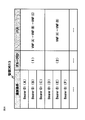
- FIG. 12 is a data configuration diagram schematically illustrating a first configuration example of information included in the management DB according to the fourth embodiment.
- FIG. 13 is a data configuration diagram schematically illustrating a second configuration example of information included in the management DB according to the fourth embodiment.
- FIG. 14 is a data configuration diagram schematically illustrating a third configuration example of information included in the management DB according to the fourth embodiment.
- FIG. 15 is a block diagram illustrating a first example of a functional configuration of a server according to the fifth embodiment of the present invention.
- FIG. 16 is a block diagram illustrating a second example of the functional configuration of the server according to the fifth embodiment.
- FIG. 17 is a block diagram illustrating a third example of the functional configuration of the server according to the fifth embodiment.
- FIG. 18 is a configuration diagram illustrating an example of a communication system according to the fifth embodiment.
- FIG. 19 is a block diagram illustrating an example of a packet classification device according to the fifth embodiment.
- FIG. 20 is a configuration diagram illustrating another example of the communication system according to the fifth embodiment.
- FIG. 20 is a configuration diagram illustrating another example of the communication system according to the fifth embodiment.
- FIG. 21 is a block diagram illustrating an example of a transfer device according to the fifth embodiment.
- 22 is a data configuration diagram schematically illustrating a configuration example of information included in the transfer device illustrated in FIG. 21.
- FIG. 23 is a block diagram illustrating an example of a functional configuration of a control device according to the sixth embodiment of the present invention.
- FIG. 24 is a data configuration diagram schematically illustrating a first configuration example of information included in the management DB illustrated in FIG. 23.
- FIG. 25 is a block diagram illustrating an example of a functional configuration of a control unit of the server according to the sixth embodiment.
- FIG. 26 is a block diagram illustrating an example of a functional configuration of a transfer device according to the sixth embodiment.
- FIG. 27 is a block diagram illustrating an example of a functional configuration of a server according to the seventh embodiment of the present invention.
- FIG. 28 is a data configuration diagram schematically illustrating a first configuration example of information included in the management DB according to the seventh embodiment.
- FIG. 29 is a data configuration diagram illustrating an example of information included in the management DB for schematically describing the path changing operation according to the seventh embodiment.
- FIG. 30 is a data configuration diagram schematically illustrating a second configuration example of information included in the management DB according to the seventh embodiment.
- FIG. 31 is a block diagram showing an example of the functional configuration of the operation management apparatus according to the eighth embodiment of the present invention.
- FIG. 32 is a block diagram illustrating another example of the functional configuration of the operation management apparatus according to the eighth embodiment.
- a virtual machine is constructed for each of various network functions (Network Function: NF) included in a network node of a communication system.
- Network Function Network Function: NF
- NF Network Function
- FIG. 1 shows a configuration example of a communication system according to the first embodiment.
- FIG. 1 illustrates an LTE (Long Term Evolution) communication system
- the communication system of the present invention is not limited to the example of FIG.
- a terminal 1 connects to a base station 2 and accesses the Internet or the like via a core network.
- the core network is composed of, for example, a gateway 3 and an MME (Mobility Management Entity) 4.
- the gateway 3 includes network nodes such as S-GW (Serving Gateway) and P-GW (Packet Data Network Gateway).
- S-GW Serving Gateway
- P-GW Packet Data Network Gateway
- Each network node performs various signal processing related to communication services provided by the communication system.
- the MME 4 executes signal processing related to the mobility management of the terminal 1.
- the network nodes (base station 2, gateway 3, MME 4) illustrated in FIG. 1 can be virtualized for each network function included in each node.
- the network node virtualized according to the present embodiment is not limited to the node illustrated in FIG.
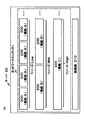
- FIG. 2 shows a configuration example of the server 20 that virtualizes network nodes.
- the control unit 210 of the server 20 can operate a plurality of network functions A, B, C,... That is, the control unit 210 can control the virtual machine for each network function of the network node, and can operate a plurality of network functions individually.
- the control unit 210 may be configured by control software capable of executing computer virtualization, such as a hypervisor.
- the plurality of network functions executed in the network node are functions related to signal processing executed in the network node, for example, and services such as data communication are provided to the user by the signal processing.
- the network node illustrated in FIG. 1 includes, for example, the following network functions.
- P-GW ⁇ Packet processing function (User-Plane function) -Function to manage the billing status according to communication (PCEF: Policy and Charging Enforcement Function) ⁇ Function to control policies such as QoS (PCRF: Policy and Charging Rule Function) -Lawful Interception (LI) function
- S-GW for intercepting communications: ⁇ Packet processing function (User-Plane function) ⁇ Function to process control signaling (C-Plane function)
- MME ⁇ Function to process control signaling (C-Plane function); for example, setting / release of communication session, control of handover, etc.
- ⁇ Manages subscriber information of communication system in cooperation with HSS (Home Subscriber Server)
- Functional base station -Function to perform digital baseband signal processing-Function to perform analog RF (Radio Frequency) signal processing.
- the control unit 210 can operate each of the network functions as a virtual network function (VNF: Virtual Network Function) 200 on the virtual machine.
- VNF Virtual Network Function
- the above function is an example, and the function that the control unit 210 can operate on the virtual machine is not limited to the above example.
- the network node of the present invention is not limited to the above example.
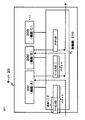
- control unit 210 can also operate the functions of a plurality of types of network nodes (network entities (1) and (2) in FIG. 3) on the virtual machine.
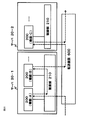
- the VNF 200 may be divided and arranged in a plurality of servers 20.
- the VNFs 200 corresponding to the functions A and B may be arranged in the server 20 (1)
- the VNFs 200 corresponding to the function C may be arranged in the server 20 (2).
- the control unit 210 can transfer the received signal to the VNF 200 and execute signal processing according to the function of the VNF 200.
- the VNF 200 performs signal processing corresponding to the function on signals such as communication data such as packets, bearer communication data, and messages received by the network node.
- FIG. 4 shows a configuration example of the control unit 210.
- the control unit 210 includes, for example, a VM (Virtual Machine) control unit 2100 and a path control unit 2101.
- VM Virtual Machine
- the VM control unit 2100 controls a virtual machine for operating the VNF 200 corresponding to the signal processing executed by the network node.
- the VM control unit 2100 can execute at least one of starting, deleting, and stopping a virtual machine.
- the VM control unit 2100 can also migrate (migrate) an operating virtual machine to another virtual machine.
- the VM control unit 2100 can also control the start / stop, migration, etc. of the virtual machine according to the status of the communication system. For example, the VM control unit 2100 dynamically starts / stops, migrates, etc. the VNF 200 according to the communication volume of the communication system, the congestion status, the load on the server 20, and the like. Further, for example, the VM control unit 2100 executes control such as activation of a new virtual machine and migration from an operating virtual machine to another virtual machine according to the load of the virtual machine executing the VNF 200.
- the path control unit 2101 transfers the received reception signal to the VNF 200.
- the VNF 200 performs corresponding signal processing on the signal transferred from the path control unit 2101.
- FIG. 5 shows an operation example of the server 20 according to the first embodiment.
- the control unit 210 can control the virtual machine for each network function of the network node (operation S10). For example, the control unit 210 starts or stops a virtual machine corresponding to each function of the network node.
- control unit 210 When receiving the signal (operation S11), the control unit 210 transfers the received signal to the VNF 200 (operation S12). The VNF 200 performs corresponding signal processing on the signal transferred from the control unit 210 (operation S13).
- the VNF 200 through which a received signal passes can be controlled according to the type of signal.
- the VNF 200 according to the type of signal flexible signal processing according to communication can be realized.
- the technology according to the second embodiment can be applied to both the first embodiment described above and the embodiments described later.
- the control unit 210 of the server 20 can control a path (hereinafter, referred to as a VNF path) representing the VNF 200 through which a received signal passes.
- a VNF path representing the VNF 200 through which a received signal passes.
- the control unit 210 can control the VNF path through which the received signal passes according to the type of signal.
- the type of signal is, for example, the type of a bearer that is a virtual connection for transmitting a packet, the attribute of a packet identified based on information in the packet, and the like.
- control unit 210 sets a VNF path passing through VNFs (A), (B), and (C) for the signal (1), and VNF ( A VNF path via A) and (B) is set.
- the controller 210 can transfer the packet along the set VNF path.
- the control unit 210 can transfer a packet based on a MAC address, an IP address, or the like assigned to the VNF 200.
- the path control unit 2101 of the control unit 210 controls the VNF path representing the VNF 200 through which the received signal passes, but according to the present embodiment, the VNF path can be controlled according to the type of signal.
- the path control unit 2101 can control the VNF path based on, for example, the communication volume of the user (terminal 1), the communication load / communication volume of the communication system, the load status of the server 20, and the like.
- the path control unit 2101 controls the VNF path of the packet belonging to the bearer according to the bearer traffic. For example, when the traffic exceeds a predetermined threshold, the VNF path is changed.
- the path control unit 2101 can select the VNF 200 configuring the VNF path according to the load status of the virtual machine. For example, the path control unit 2101 preferentially selects a VNF 200 with a low virtual machine load from a plurality of VNFs 200 including the same function, and configures a VNF path.
- the control unit 210 may be configured by, for example, a virtual switch (vSwitch: Virtual Switch) configured by software.
- vSwitch Virtual Switch
- FIG. 7 shows an operation example of the server according to the second embodiment.
- the control unit 210 controls a virtual machine for executing the VNF 200 on the server 20 (operation S20). For example, the control unit 210 executes activation, stop, migration, and the like of the virtual machine. In the example of FIG. 7, the control unit 210 activates a virtual machine for executing the VNF 200 corresponding to each of the functions A, B, and C of the network node.
- control unit 210 When receiving the signal (1) (operation S21), the control unit 210 controls the VNF path so that the signal (1) passes through the corresponding VNF 200 (S22).
- control unit 210 When receiving the signal (2) (operation S23), the control unit 210 controls the VNF path so that the signal (2) passes through the corresponding VNF 200 (operation S24).
- Third Embodiment In the third embodiment of the present invention, a variation related to control of a virtual machine for executing the VNF 200 is illustrated. That is, according to the third embodiment, the virtual machine is controlled in a variety of ways, for example, the utilization efficiency of computing resources (CPU, memory, storage, etc.) used for the virtual machine is improved, and the status regarding the virtual machine Advantages such as simplified management can be obtained.
- the technique of the third embodiment can be applied not only to the first and second embodiments described above, but also to any embodiment described later. Hereinafter, the third embodiment will be described using the configuration of the control unit 210 illustrated in FIG. 4.
- the VM control unit 2100 of the control unit 210 can control computing resources allocated to a virtual machine corresponding to the VNF 200 according to the type of the VNF 200.
- the VM control unit 2100 may change the frequency of dynamic scaling of the virtual machine corresponding to the VNF 200 (for example, dynamic start, stop, deletion, migration, etc. of the virtual machine) according to the type of the VNF 200.
- the computing resource allocated to the virtual machine can be controlled.
- the VM control unit 2100 can control computing resources allocated to the virtual machine so that performance degradation due to dynamic scaling of the VNF 200 that manages the communication status is suppressed.
- FIG. 8 shows a first configuration example of the server 20 according to the third embodiment.
- the VM control unit 2100 of the control unit 210 controls computing resources allocated to the virtual machine corresponding to the VNF 200 according to the function provided by the VNF 200. More specifically, the VM control unit 2100 changes the allocation of computing resources allocated to the VNF 200 in accordance with each function provided by the VNF 200 (functions A, B, and C in FIG. 8). In this example, the VM control unit 2100 controls the amount of resources (Low, Mid, High) allocated to each VNF 200 according to the function of the VNF 200.
- the MME 4 includes a function for managing a bearer context.
- the bearer context is described in, for example, Chapter 5.7 of a document (TS23.401 V12.3.0) regarding technical specifications (3GPP: 3rd Generation Partnership Project) regarding wireless communication.
- the P-GW may include a function (PCEF) that manages charging according to the traffic.
- PCEF function
- the VM control unit 2100 migrates to another virtual machine including the communication status of the VNF 200, for example, when the VNF 200 is migrated to another virtual machine. Therefore, it can be considered that as the information amount of the communication status is larger, the time required for the transition of the communication status becomes longer, and the performance of the communication service regarding the VNF 200 during the transition is lowered. Therefore, when the VNF 200 provides a function for managing the communication status, it is possible to suppress the performance degradation of the communication service by suppressing the execution of scale-out such as addition or migration of the VNF 200.
- the VM control unit 2100 allocates more resources than the resources set based on performance requirements or the like to the VNF 200 including the communication status management function. That is, by allocating surplus resources to the VNF 200, scale-out such as VNF addition or migration can be suppressed, and the above-described performance degradation can be avoided.
- the VM control unit 2100 can control the resource amount allocated to the VNF 200 based on the communication status update frequency by the VNF 200 instead of the function provided by the VNF 200.
- the VM control unit 2100 may allocate surplus resources to the VNF 200 that provides a function with a high communication status update frequency (for example, PCEF of P-GW).
- FIG. 9 shows a second configuration example of the server 20 according to the third embodiment.
- the VM control unit 2100 controls the frequency of dynamic scaling (hereinafter referred to as “change frequency”) such as addition or migration of the VNF 200 according to the function of the VNF 200.
- change frequency the frequency of dynamic scaling
- the addition or migration of the VNF 200 is executed in accordance with, for example, the load status of the communication system or the virtual machine.
- the VNF is changed by adjusting the threshold value of the load status where the VNF 200 is added or migrated.
- the frequency can be controlled.
- the VM control unit 2100 can control the change frequency of the VNF according to the presence / absence of the communication status management function and the update frequency of the communication status. More specifically, when the VNF 200 includes a function for frequently updating the communication status (for example, PCEF), the VM control unit 2100 sets the change frequency of the VNF 200 to be lower than the change frequency set based on performance requirements or the like. . In addition, when the VNF 200 includes a function with a low communication status update frequency (for example, the U-Plane function), the VM control unit 2100 sets the change frequency of the VNF 200 higher than the change frequency set based on performance requirements or the like. Or set to the same level.
- a function for frequently updating the communication status for example, PCEF
- the VM control unit 2100 sets the change frequency of the VNF 200 to be lower than the change frequency set based on performance requirements or the like.
- the VNF 200 includes a function with a low communication status update frequency (for example, the U-Plane function)
- FIG. 10 shows a third configuration example of the server 20 according to the third embodiment.
- the VM control unit 2100 can control each VNF 200 so that the communication status regarding each of the plurality of VNFs 200 is centrally managed.
- the server 20 includes a shared DB (Data Base) 220.
- the shared DB 220 is a database that stores information related to the communication status.
- each VNF 200 activated on the server 20 can acquire information on the communication status with reference to the shared DB 220.
- each VNF 200 can store information on the communication status changed according to the signal processing in the shared DB 220.
- the shared DB 220 is installed outside the server 20, and can exchange information through a network or a dedicated line.
- the VM control unit 2100 controls each VNF 200 so that the communication status related to signal processing by each VNF 200 is managed by the shared DB 220.
- the function for managing the communication status is separated from the VNF 200 by managing the information related to the communication status in the database shared by the VNF 200. Therefore, even when the VM control unit 2100 migrates the VNF 200 to another virtual machine, for example, it is not necessary to include a communication status, and performance degradation due to VNF scale-out can be suppressed.
- the migrated VNF 200 can take over the communication status related to the migration source VNF 200 by referring to the shared DB 220.
- the third example shown in FIG. 10 can be combined with the first example or the second example shown in FIG. 8 or FIG.
- the control device 10 controls the VNF 200 on the server 20. Since the control device 10 can centrally control the VNF 200, the management efficiency of the VNF 200 is improved.
- the technology of the fourth embodiment can be applied to the first to third embodiments and any of the embodiments described later.
- FIG. 11 shows a configuration example of the control device 10.
- the control device 10 includes a VM control unit 11, a path control unit 12, a management DB 13 and an interface 15.
- the control device 10 can communicate with the server 20 via the interface 15.
- the VM control unit 11 can instruct the control unit 210 of the server 20 to control the VNF 200 as in the first to third embodiments described above.
- the VM control unit 11 instructs, for example, the VM control unit 2100 of the control unit 210 to start / stop the virtual machine that executes the VNF 200, to migrate the operating virtual machine to another virtual machine, and the like.
- the VM control unit 11 can instruct the VM control unit 2100 of the control unit 210 to control resources allocated to the VNF 200 according to the functions provided by the VNF 200. .
- the VM control unit 11 can instruct the control unit 210 to control the VNF 200 as in an embodiment described later.
- the path control unit 12 can instruct the control unit 210 of the server 20 to control the VNF path through which the received signal passes, as in the first and second embodiments described above.
- the path control unit 12 notifies the path control unit 2101 of the control unit 210 of information indicating a VNF path according to the type of signal.
- the path control unit 2101 refers to the notified information, identifies the VNF path corresponding to the received signal, and transfers the received signal to the VNF 200 on the identified VNF path.
- the VNF 200 processes the received signal transferred from the path control unit 2101.
- the path control unit 12 can determine the VNF path based on, for example, the communication volume of the user (terminal 1), the communication load / communication volume of the communication system, the load status of the server 20, and the like. The path control unit 12 notifies the path control unit 2101 of the determined VNF path.
- the VM control unit 11 can also instruct the control unit 210 to control the VNF path as in an embodiment described later.
- FIG. 12 shows an example of the data configuration of the management DB 13.
- the management DB 13 includes an identification condition for the path control unit 2101 of the server 20 to identify a communication type and information indicating a VNF path corresponding to the identification condition.
- the path control unit 12 determines a VNF path according to the communication type.
- the path control unit 12 stores the determined VNF path and the communication type identification condition corresponding to the VNF path in the management DB 13.
- the path control unit 12 sets identification conditions by information that can identify UE (User Equipment) such as IMSI (International Mobile Subscriber Identity), TMSI (Temporary Mobile Subscriber Identity), and the like. Further, the path control unit 12 sets an identification condition by information that can identify a bearer such as TEID (Tunnel Endpoint Identifier) and GRE (Generic Routing Encapsulation) key.
- UE User Equipment
- IMSI International Mobile Subscriber Identity
- TMSI Temporary Mobile Subscriber Identity
- a bearer such as TEID (Tunnel Endpoint Identifier) and GRE (Generic Routing Encapsulation) key.
- the path control unit 12 can determine the VNF path based on a predetermined parameter. For example, the path control unit 12 can determine the VNF path based on the traffic (for example, the packet count), the status of the server 20 or the virtual machine (for example, the load status), and the like. Further, the path control unit 12 can compare the above parameter with a predetermined threshold value and change the VNF path according to the comparison result.
- the traffic for example, the packet count
- the status of the server 20 or the virtual machine for example, the load status
- the path control unit 12 can compare the above parameter with a predetermined threshold value and change the VNF path according to the comparison result.
- the path control unit 12 can select the VNF 200 constituting the VNF path according to the load status of the server 20 or the virtual machine. For example, the path control unit 12 preferentially selects a VNF 200 that is virtual on a virtual machine with a low load among a plurality of VNFs 200 including the same function, and configures a VNF path. In addition, for example, the path control unit 12 preferentially selects the VNF 200 operating on the server 20 with a low load among the plurality of VNFs 200 including the same function, and configures the VNF path.
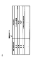
- FIG. 13 shows another example of the data configuration of the management DB 13.
- the path control unit 12 can generate information representing a VNF path using an identifier for identifying each VNF 200 and store the information in the management DB 13.
- the VM control unit 11 may manage the identifier and the attribute of the VNF 200 corresponding to the identifier (for example, the function included in the VNF 200). As illustrated in FIG. 14, the VM control unit 11 can store information including an identifier and the function of the VNF 200 corresponding to the identifier in the management DB 13. The path control unit 12 can determine the VNF path with reference to the information illustrated in FIG.
- control device 10 may be provided by the MME 4 or the gateway 3 (for example, the PCRF function of P-GW). That is, the MME 4 or the gateway 3 can also operate as the control device 10 described above.
- the control unit 210 can transfer the signal to a virtual machine that operates a network function corresponding to the signal, based on tag information included in the received signal.
- the control unit 210 of the server 20 can specify the VNF 200 or the VNF path corresponding to the signal based on the tag information.
- the tag information is generated according to a predetermined rule (for example, a protocol defined by a standard specification or the like) so as to indicate a VNF 200 or VNF path corresponding to the signal, for example.
- the control unit 210 refers to the additional header added as tag information to the received packet, and transfers the packet along the VNF path.
- the additional header includes information regarding the VNF path. Since the control unit 210 can transfer the packet based on the information included in the received packet, it does not have to manage the route information corresponding to the VNF path. Therefore, the control unit 210 can execute packet transfer along the VNF path with a simpler configuration.
- the control unit 210 specifies, for example, the VNF 200 included in the VNF path and the order in the VNF path based on the information of the additional header, and transfers the packet based on the specified VNF 200 and the order.
- the control unit 210 may delete the additional header from the packet when the processing at the last VNF 200 in the VNF path is completed.
- control unit 210 may transfer the packet with reference to the additional header configured with the identifier of the VNF 200.
- the additional header includes an identifier of the VNF 200 corresponding to the VNF path.
- the additional header stores the identifier of each VNF 200 in the order of each VNF 200 in the VNF path.
- the control unit 210 refers to the identifier according to the order stored in the additional header, and transfers the packet to the VNF 200 corresponding to the identifier.
- the control unit 210 refers to the identifier A (ID: A) and the identifier B (ID: B) in this order, and transfers the packet to the VNF 200 corresponding to each identifier.
- the controller 210 may delete the referenced identifier from the additional header as in the example of FIG. 16, and in this example, the identifier is deleted in the order of ID: A and ID: B.
- the control unit 210 may transfer the packet with reference to an additional header configured with an identifier (“service ID” in FIG. 16) indicating a communication service related to the packet.
- the service ID is information that can identify a communication service such as a moving image distribution service, an SNS (Social Network Service) service, or the like.
- the control unit 210 includes, for example, information related to the VNF path associated with each service ID. Based on the information and the service ID given to the received packet, the control unit 210 identifies the VNF path corresponding to the service ID. The control unit 210 may delete the additional header from the packet when the processing at the last VNF 200 in the VNF path is completed.
- a function of adding an additional header to a packet may be arranged in the communication system.
- the function of adding the additional header is arranged at the boundary with the external network in the data center where the server 20 is arranged, for example.
- the function of adding an additional header adds an additional header to a packet received from an external network and transfers the packet into the data center.
- FIG. 18 shows an example of a system in which the above-described additional header assignment function is arranged.
- the packet classification device 230 adds an additional header to the packet.
- the packet classification device 230 is disposed, for example, at the boundary between the data center and the external network (for example, the edge of the communication system).
- the packet classification device 230 classifies the received packet, and adds an additional header according to the content of the packet to the packet.
- the packet classification device 230 can generate an additional header with a predetermined rule so as to indicate a VNF path through which the packet passes.
- the packet classification device 230 can identify the VNF 200 corresponding to the packet.
- FIG. 19 shows a configuration example of the packet classification device 230.
- the packet classification device 230 includes a storage unit 2300, a packet processing unit 2301, and an interface 2302.
- the packet classification device 230 can communicate with the control device 10 via the interface 2302.
- the storage unit 2300 includes, for example, information having the same configuration as that of the management DB 13 illustrated in FIG. 12 or FIG.
- the storage unit 2300 may include information including an identification condition for identifying the type of communication service and a service ID corresponding to the identification condition.
- the packet processing unit 2301 refers to the storage unit 2300 and adds an additional header to the packet. For example, the packet processing unit 2301 identifies the received packet based on the identification condition stored in the storage unit 2300, and adds information indicating the VNF path corresponding to the identification condition matching the packet to the packet as an additional header. .
- the VNF path may be a path that passes through a plurality of servers 20.
- the VNF path passes through the VNF 200 operating on the server 20-1 and the VNF 200 operating on the server 20-2.
- the packet classification device 230 may be configured by a virtual switch or the like configured by software such as a virtual machine.
- the function of the packet classification device 230 can be executed by a virtual switch operating on a server arranged at the edge of the communication system.
- the transfer device 600 can transfer a packet along a path that passes through a plurality of servers 20.
- a packet processed by the VNF 200 including the function B is transferred to the VNF 200 (VNF including the function C) operating on the server 20-2.
- FIG. 21 shows a configuration example of the transfer device 600.
- Transfer device 600 includes a storage unit 610 and a packet processing unit 620.
- the storage unit 610 includes, for example, information of the configuration illustrated in FIG.
- the control device 10 can notify the transfer device 600 of the information illustrated in FIG.
- the storage unit 610 includes information including packet identification conditions and packet processing rules corresponding to the identification conditions.
- the identification condition is a condition for identifying a packet based on information that can identify a UE such as IMSI or TMSI, or information that can identify a bearer such as TEID or GRE Key.
- the identification condition may be, for example, a condition for identifying a packet based on the above-described additional header.
- the packet processing unit 620 compares the above-described identification condition with the packet, and processes the packet according to the processing rule corresponding to the identification condition matching the packet.
- control device 10 monitors the status of the server 20, the virtual machine, and the like, and controls the VNF 200 or the VNF path according to the monitoring result. Therefore, according to the sixth embodiment, the control device 10 can execute resource control according to the status of the communication system.
- the technique of the sixth embodiment can be applied to both the above-described first to fifth embodiments and the later-described embodiments.
- FIG. 23 shows a configuration of the control device 10 according to the present embodiment.
- the control device 10 includes a status collection unit 14 in addition to the configuration exemplified in the above-described embodiment.
- the status collection unit 14 collects information from the server 20 or the transfer device 600, and stores information of the configuration illustrated in FIG. 24 in the management DB 13 based on the collected information.
- the status collection unit 14 can store the status corresponding to each VNF 200 in the management DB 13.
- the status collection unit 14 can collect the load status (“VM Load” and “Server Load” in FIG. 24) of the virtual machine or server 20 corresponding to each VNF 200 and store it in the management DB 13.
- the load status () of the communication path related to each VNF 200 may be collected.
- the status collection unit 14 can also collect the number of packets () counted by the VNF 200 including a predetermined function (for example, PCEF).
- the status collection unit 14 can collect the number of packets counted by the VNF 200 including the PCEF function for each bearer and store it in the management DB 13.
- the path control unit 12 of the control device 10 can monitor whether the number of packets counted by the VNF 200 including the PECF function exceeds a predetermined threshold for each bearer. For example, the path control unit 12 can delete the VNF 200 including the PCEF function from the VNF path related to the bearer whose number of packets has exceeded a predetermined threshold. After the number of packets, which is a predetermined threshold, is exceeded, the user may conclude a contract with a communication operator that charges a flat rate charge regardless of the number of packets. In this case, after the number of packets exceeds a predetermined threshold, the communication operator can charge the user even if the VNF 200 including the PCEF function does not count the number of packets. Therefore, as described above, by deleting the VNF 200 including the PCEF function from the VNF path, the path control unit 12 can allocate the resource of the VNF 200 to another bearer.
- the VM control unit 11 can monitor the amount of the control signal (C-Plane Signaling) of the network node based on the information collected by the status collection unit 14.
- the VM control unit 11 adds a VNF 200 having a function for processing a control signal (for example, a VNF corresponding to the C-Plane function of the MME4 and the C-plane function of the gateway 3) according to the increase of the control signal. be able to.
- the path control unit 12 determines that the VNF path includes a VNF 200 having a lawful interception function (lawful interception function) of the P-GW according to the UE position monitored by the status collection unit 14. Can be controlled. For example, there is a country where a lawful intercept function is required in the P-GW. In such a case, the path control unit 12 includes the VNF 200 having the required function in the VNF path according to the location of the UE. To control.
- a lawful interception function lawful interception function
- FIG. 25 shows a configuration example of the control unit 210 in the server 20 according to the sixth embodiment.
- the control unit 210 includes a status notification unit 2102 in addition to the configuration exemplified in the above-described embodiment.
- the status notification unit 2102 can monitor the load status of the virtual machine corresponding to the VNF 200, the load status of the server 20, the communication status related to the VNF 200 or the server 20, and the like.
- the status notification unit 2102 can also monitor the operating status of each VNF 200 (for example, the packet count by the VNF 200).
- the status notification unit 2102 notifies the control apparatus 10 of the monitored information.
- the status collection unit 14 of the control device 10 stores information in the management DB 13 based on the information notified from the status notification unit 2102 of the server 20.
- FIG. 26 shows a configuration example of the transfer device 600 in the sixth embodiment.
- the transfer device 600 includes a status notification unit 630 in addition to the configuration exemplified in the above-described embodiment.
- the status notification unit 630 monitors the communication status such as the traffic volume and the load on the transfer device 600.
- the status notification unit 630 notifies the control device 10 of the monitored information.
- a VNF path is set for each group composed of a plurality of types of signals. Therefore, it becomes possible to collectively control VNF paths related to a plurality of types of signals, and the operation efficiency of the communication system is improved.
- the technique of the seventh embodiment can be applied to the above-described first to sixth embodiments and any of the embodiments described later.
- FIG. 27 shows a configuration example of a server according to the seventh embodiment.
- the control unit 210 of the server 20 can set a VNF path for each group of a plurality of signals.
- the control unit 210 can set a VNF path for each group of a plurality of bearers.
- the control unit 210 can perform transfer based on the additional header as illustrated in FIGS. 15 to 19 of the fifth embodiment. That is, the received signal can be transferred based on the additional header including information on the VNF 200 or the VNF path corresponding to the group.
- the control device 10 can manage a plurality of signals as a group, and can control the VNF path for each group.
- the control device 10 can also instruct the packet classification device 230 in the fifth embodiment to add an additional header corresponding to the group to the packet.
- FIG. 28 shows a data configuration example of the management DB 13 of the control device 10.
- the path control unit 12 of the control device 10 can instruct the control unit 210 of the server 20 to control the VNF path based on the information illustrated in FIG.
- the management DB 13 includes identification conditions set based on bearer identifiers such as TEID, a group ID indicating a group of a plurality of bearers, and information on the VNF paths of the group.
- bearer identifiers such as TEID, a group ID indicating a group of a plurality of bearers, and information on the VNF paths of the group.
- the control apparatus 10 can group bearers according to the attribute of UE corresponding to each bearer, for example. Examples of UE attributes are shown below.
- -UE stay area E-UTRAN Cell ID, etc.
- Charging characteristics related to UE normal charging, prepaid charging, flat rate, etc.
- -UE communication status whether or not a certain amount of communication has been performed in a certain period
- -Operator ID ID of the operator of the core network to which the terminal 1 is connected
- PDN Packet Data Network
- IDLE state Packet Data Network
- CONNECTED state a state in which the UE does not continuously exchange control signals for session management and mobility management with the core network, Or, it means a state where the wireless connection with the base station is released.
- the CONNECTED state means, for example, a state where the UE is continuously exchanging control signals for session management and mobility management with the core network, or a state where the UE is
- the control apparatus 10 can group bearers according to other attributes.
- the control device 10 groups bearers based on information on UE (User Equipment) in “EPS Bearer Context” disclosed in Chapter 5.7 of the standard specification (3GPP TS23.401). Is possible.
- control apparatus 10 can also group bearers according to the contract contents between the user of the UE and the communication carrier.
- the control device 10 groups bearers related to users (for example, “Premium Subscriber”) who have concluded a contract with a communication carrier higher than other users, and / or bearers related to users of normal contracts. Can be grouped.
- control device 10 can group bearers based on information on the UE location (for example, GSP information, base station information to which the terminal 1 is attached). For example, it is possible to group bearers of UEs that are close to each other based on information on the location.
- control device 10 can also group bearers according to bearer QoS (Quality of Service) information.
- bearer QoS Quality of Service
- control apparatus 10 can group bearers according to QCI (Quality Class Indicator) corresponding to each bearer.
- the path control unit 12 of the control device 10 can instruct the control unit 210 of the server 20 to change the VNF path for each group ID. Therefore, the path control unit 12 can collectively control VNF paths related to a plurality of bearers belonging to the group. In the example of FIG. 29, the path control unit 12 instructs the control unit 210 to change the VNF path corresponding to the group (1).
- the control unit 210 has the same information as the database illustrated in FIG. 28, and can recognize a bearer group, a bearer belonging to the group, and a VNF path of the group. The control unit 210 can change the VNF path corresponding to the bearer group in accordance with an instruction from the path control unit 12.
- each bearer identifier (for example, TEID) may be assigned so that identifiers of a plurality of bearers belonging to the group can be collectively identified.
- the TEID is assigned to each of a plurality of bearers belonging to the group so that the upper 24 bits of the TEID configured by 32-bit information are the same.
- the control unit 10 and the control unit 210 of the server 20 can collectively identify a plurality of bearers belonging to the group based on the upper 24 bits of the TEID.
- the operator of the communication system sets an operation policy in the control device 10, and the control device 10 sets the VNF 200 or the VNF path according to the set operation policy. It can be controlled automatically. By enabling automatic operation by the control device 10, the operation efficiency of the communication system is improved.
- the technique of the eighth embodiment can be applied to the above-described first to seventh embodiments and any of the embodiments described later.
- the operator of the communication system can set an operation policy in the control device 10 using the operation management device 30.
- the operator can also set an operation policy by directly operating the control device 10.
- FIG. 31 shows a configuration example of the operation management apparatus 30.
- the operation management apparatus 30 includes a VNF management unit 31, a path management unit 32, and an interface 34.
- the operation management apparatus 30 can communicate with the control apparatus 10 via the interface 34.
- the VNF management unit 31 can set a virtual machine operation policy related to the VNF 200 to the VM control unit 11 of the control device 10. For example, the VNF management unit 31 sets parameters that are triggers for starting, stopping, and migrating virtual machines, and threshold values for determining whether or not to run, stop, and migrate virtual machines based on the parameters. Can be set in the VM control unit 11.
- Parameters that trigger virtual machine startup, stop, migration, etc. are, for example, the load on the virtual machine, the load on the server 20, the communication load related to the virtual machine, the communication volume of the virtual machine, and the like.
- the VM control unit 11 can acquire information on the parameters via the status collection unit 14 illustrated in the fifth embodiment. The VM control unit 11 compares the acquired information with the threshold value notified from the operation management apparatus 30, and determines whether or not execution, stop, deletion, migration, etc. of the virtual machine is necessary.
- the VNF management unit 31 sets an operation policy for changing the allocation of computing resources (CPU, memory, etc.) of the virtual machine according to the function of the VNF 200.
- the VM control unit 11 may be set.
- the VM control unit 11 controls the control unit 210 of the server 20 so that virtual machine resources are allocated according to the operation policy.
- the VNF management unit 31 performs VM control on an operation policy for changing the frequency of starting, stopping, migrating, etc. of a virtual machine according to the function of the VNF 200.
- You may set to the part 11.
- the VNF management unit 31 sets a threshold value related to execution such as starting, stopping, and migrating a virtual machine according to the type of function provided by the VNF 200.
- the VM control unit 11 operates the virtual machine according to the policy notified from the VNF management unit 31 to change the frequency of VNF activation, stop, migration, etc. according to the type of the VNF 200.
- the path management unit 32 can set an operation policy related to the VNF path for the path control unit 12 of the control device 10.
- the path management unit 32 can set, for example, a policy for constructing a VNF path, a policy for changing the VNF path, and the like in the path control unit 12.
- the path management unit 32 can set, for example, an operation policy for selecting the VNF 200 configuring the VNF path in the path control unit 12 according to the bearer attribute, the UE attribute regarding the bearer, the type of communication service, and the like.
- the path management unit 32 can set an operation policy for selecting the VNF 200 according to the position of the UE in the path control unit 12.
- the path management unit 32 can set the operation policy such that the VNF 200 having the lawful intercept function of P-GW (Lawful Interception function) is included in the VNF path according to the location of the UE.
- P-GW Lawful Interception function
- the path management unit 32 can set the operation policy so that the VNF 200 having the required function is included in the VNF path according to the location of the UE.
- the path management unit 32 can specify the VNF 200 that configures the VNF path to the path control unit 12 according to the QCI (QoS Class Identifier) associated with the bearer. That is, the path management unit 32 can instruct the path control unit 12 to change the function of the virtual network node corresponding to the bearer according to the bearer attribute.
- the path management unit 32 can set an operation policy such that a VNF path is configured by the VNF 200 to which computing resources according to QCI are allocated.
- the path management unit 32 can set the operation policy such that the higher the QCI, the greater the resource amount of the VNF 200 that configures the VNF path.
- the path management unit 32 can also specify, for example, the VNF 200 that configures the VNF path according to the UE attribute exemplified in the seventh embodiment, with respect to the path control unit 12. That is, the path management unit 32 can instruct the path control unit 12 to change the function of the virtual network node corresponding to the UE according to the attribute of the UE.
- the path management unit 32 can also specify, for example, the VNF 200 configuring the VNF path to the path control unit 12 according to the type of communication service. That is, the path management unit 32 can instruct the path control unit 12 to change the function of the virtual network node corresponding to the communication service according to the type of the communication service.
- the path management unit 32 can instruct the path control unit 12 to switch the high-load VNF 200 in the VNF path to another VNF 200 having the same type of function according to the load status of the VNF 200, for example.
- FIG. 32 shows another configuration example of the operation management apparatus 30.
- the operation management apparatus 30 includes a data analysis unit 33.
- the data analysis unit 33 collects the status related to the server 20 or the virtual machine and the status related to the network, and analyzes the collected information.
- the data analysis unit 33 can instruct the VNF management unit 31 and the path management unit 32 to change the operation policy described above according to the analysis result.
- the data analysis unit 33 acquires, for example, information collected by the status collection unit 14 exemplified in the sixth embodiment.
- the data analysis unit 33 can change the operation policy based on the analysis result.
- the data analysis unit 33 can change a threshold value for determining whether or not to start, stop, migrate, etc. a virtual machine based on the analysis result. For example, the data analysis unit 33 can lower the threshold regarding the addition of the VNF 200 having a function for processing the control signal in accordance with an increase in the control signal (C-Plane Signaling) of the network node. Further, the data analysis unit 33 can change the operation policy so that the resource amount of the VNF 200 having a function for processing the control signal increases as the control signal increases.
- the data analysis unit 33 can change the operation policy related to the VNF path based on the analysis result. For example, the data analysis unit 33 can change the operation policy so that a predetermined VNF 200 (for example, a VNF that does not affect the continuity of the communication service) in the VNF path is deleted according to an increase in the load on the communication system. . Since the resources of the deleted VNF 200 can be accommodated to other VNFs 200, a performance decrease accompanying an increase in the load on the communication system is suppressed.
- a predetermined VNF 200 for example, a VNF that does not affect the continuity of the communication service
Abstract
Description
本発明は、仮想マシンの制御に係り、特に、通信システムにおける仮想マシンの制御に関する。 The present invention is based on the priority claim of the Japanese patent application filed on March 4, 2014: Japanese Patent Application No. 2014-04382, the entire contents of which are incorporated herein by reference. It shall be.
The present invention relates to control of a virtual machine, and more particularly to control of a virtual machine in a communication system.
前記通信装置に対し、前記インターフェースを介して、ネットワークノードで実行される複数のネットワーク機能を、それぞれ対応する複数の仮想マシンを運用可能なサーバが、受信した信号に対応するネットワーク機能を識別するためのタグ情報を、前記信号に付加するように指示することを特徴とする制御方法が提供される。 According to the present invention, the communication device communicates with
A server capable of operating a plurality of virtual machines corresponding to a plurality of network functions executed by a network node via the interface for the communication device to identify a network function corresponding to a received signal. The control method is characterized by instructing to add the tag information to the signal.
本発明の第1の実施形態によれば、通信システムのネットワークノードが含む様々なネットワーク機能(Network Function:NF)の各々に対して、仮想マシンが構築される。これにより、たとえばノードのネットワーク機能毎に仮想マシンを増設することが可能となり、仮想マシン制御の柔軟性および適応性を向上させることができる。 1. First Embodiment According to the first embodiment of the present invention, a virtual machine is constructed for each of various network functions (Network Function: NF) included in a network node of a communication system. As a result, for example, a virtual machine can be added for each network function of the node, and the flexibility and adaptability of virtual machine control can be improved.
図2は、ネットワークノードを仮想化するサーバ20の構成例を示す。図2の例示されるように、サーバ20の制御部210は、ネットワークノードで実行される複数のネットワーク機能A、B、C・・・をそれぞれ対応する複数の仮想マシンで運用可能である。つまり、制御部210は、ネットワークノードのネットワーク機能毎に仮想マシンを制御することができ、複数のネットワーク機能を個別に運用可能である。 1.1) Server FIG. 2 shows a configuration example of the server 20 that virtualizes network nodes. As illustrated in FIG. 2, the
P-GW:
・パケットを処理する機能(User-Plane機能)
・通信に応じた課金状態を管理する機能(PCEF:Policy and Charging Enforcement Function)
・QoS等のポリシを制御する機能(PCRF:Policy and Charging Rule Function)
・通信を傍受するための合法的傍受(LI:Lawful Interception)機能
S-GW:
・パケットを処理する機能(User-Plane機能)
・制御シグナリングを処理する機能(C-Plane機能)
MME:
・制御シグナリングを処理する機能(C-Plane機能);例えば、通信用のセッションの設定/解放、ハンドオーバの制御等
・HSS(Home Subscriber Server)と連携して、通信システムの加入者情報を管理する機能
基地局:
・デジタルベースバンド信号処理を行う機能
・アナログRF(Radio Frequency)信号処理を行う機能。 The network node illustrated in FIG. 1 includes, for example, the following network functions.
P-GW:
・ Packet processing function (User-Plane function)
-Function to manage the billing status according to communication (PCEF: Policy and Charging Enforcement Function)
・ Function to control policies such as QoS (PCRF: Policy and Charging Rule Function)
-Lawful Interception (LI) function S-GW for intercepting communications:
・ Packet processing function (User-Plane function)
・ Function to process control signaling (C-Plane function)
MME:
・ Function to process control signaling (C-Plane function); for example, setting / release of communication session, control of handover, etc. ・ Manages subscriber information of communication system in cooperation with HSS (Home Subscriber Server) Functional base station:
-Function to perform digital baseband signal processing-Function to perform analog RF (Radio Frequency) signal processing.
図5は、第1の実施形態によるサーバ20の動作例を示す。 1.2) Operation FIG. 5 shows an operation example of the server 20 according to the first embodiment.
本発明の第2の実施形態によれば、信号の種別に応じて、受信信号が経由するVNF200を制御できる。信号の種別に応じてVNF200を選択することで、通信に応じた柔軟な信号処理を実現できる。第2の実施形態による技術は、上述の第1の実施形態、後述の実施形態のいずれにも適用可能である。 2. Second Embodiment According to the second embodiment of the present invention, the
図6に例示するように、サーバ20の制御部210は、受信信号が経由するVNF200を表すパス(以下、VNFパスと呼ぶ)を制御することが可能である。制御部210は、例えば、信号の種別に応じて、受信信号が経由するVNFパスを制御できる。信号の種別は、例えば、パケットを伝送する仮想的なコネクションであるベアラの種別、パケット内の情報に基づいて識別されるパケットの属性等である。 2.1) Server As illustrated in FIG. 6, the
図7は第2の実施形態によるサーバの動作例を示す。 2.2) Operation FIG. 7 shows an operation example of the server according to the second embodiment.
本発明の第3の実施形態では、VNF200を実行するための仮想マシンの制御に関するバリエーションが例示される。すなわち、第3の実施形態によれば、仮想マシンが多様に制御されることにより、例えば、仮想マシンに用いられるコンピューティングリソース(CPU、メモリ、ストレージ等)の利用効率の向上、仮想マシンに関するステータス管理の簡略化等の利点を得ることができる。第3の実施形態の技術は、上述の第1、第2の実施形態だけでなく、後述するいずれの実施形態にも適用可能である。以下、図4に示す制御部210の構成を用いて、第3の実施形態について説明する。 3. Third Embodiment In the third embodiment of the present invention, a variation related to control of a virtual machine for executing the
図8は、第3の実施形態によるサーバ20の第1構成例を示す。 <First example>
FIG. 8 shows a first configuration example of the server 20 according to the third embodiment.
図9は、第3の実施形態によるサーバ20の第2構成例を示す。 <Second example>
FIG. 9 shows a second configuration example of the server 20 according to the third embodiment.
図10は、第3の実施形態によるサーバ20の第3構成例を示す。 <Third example>
FIG. 10 shows a third configuration example of the server 20 according to the third embodiment.
本発明の第4の実施形態によれば、制御装置10が、サーバ20上のVNF200を制御する。制御装置10によりVNF200を集中制御できるので、VNF200の管理効率が向上する。第4の実施形態の技術は、第1-3の実施形態、および、後述するいずれの実施形態にも適用可能である。 4). Fourth Embodiment According to the fourth embodiment of the present invention, the
図12は、管理DB13のデータ構成の一例を示す。管理DB13は、サーバ20のパス制御部2101が通信種別を識別するための識別条件と、当該識別条件に対応するVNFパスを示す情報とを含む。パス制御部12は、例えば、通信種別に応じてVNFパスを決定する。パス制御部12は、決定したVNFパスと、当該VNFパスに対応する通信種別の識別条件とを、管理DB13に格納する。 <First example>
FIG. 12 shows an example of the data configuration of the
図13は、管理DB13のデータ構成の他の例を示す。この例では、パス制御部12は、各々のVNF200を識別するための識別子を用いてVNFパスを表す情報を生成し、管理DB13に格納することができる。 <Second example>
FIG. 13 shows another example of the data configuration of the
図13のようにVNF200の識別子が用いられる場合、VM制御部11は、識別子と、当該識別子に対応するVNF200の属性(例えば、VNF200が含む機能)とを管理してもよい。図14に例示するように、VM制御部11は、識別子と、当該識別子に対応するVNF200の機能とからなる情報を管理DB13に格納することができる。パス制御部12は、図14に例示された情報を参照し、VNFパスを決定することができる。 <Third example>
When the identifier of the
本発明の第5の実施形態では、VNFパスに沿って受信信号を処理する方法の例が示される。第5の実施形態の技術は、上述の第1-4の実施形態、および、後述するいずれの実施形態にも適用可能である。 5. Fifth Embodiment In the fifth embodiment of the present invention, an example of a method for processing a received signal along a VNF path is shown. The technique of the fifth embodiment can be applied to the above-described first to fourth embodiments and any of the embodiments described later.
図15に例示されるように、制御部210は、受信パケットにタグ情報として付加された追加ヘッダを参照し、VNFパスに沿ってパケットを転送する。追加ヘッダは、VNFパスに関する情報を含む。制御部210は、受信パケットに含まれる情報に基づいてパケットを転送できるので、VNFパスに対応する経路情報を管理しなくてもよい。よって、制御部210は、VNFパスに沿ったパケット転送を、よりシンプルな構成で実行できる。 <First example>
As illustrated in FIG. 15, the
図16に例示されるように、制御部210は、VNF200の識別子で構成された追加ヘッダを参照し、パケットを転送してもよい。追加ヘッダは、VNFパスに対応するVNF200の識別子を含む。また、追加ヘッダは、VNFパスにおける各VNF200の順に、各VNF200の識別子を格納する。 <Second example>
As illustrated in FIG. 16, the
図17に例示されるように、制御部210は、パケットに関する通信サービスを示す識別子(図16の「サービスID」)で構成された追加ヘッダを参照し、パケットを転送してもよい。サービスIDは、例えば、動画配信サービス、SNS(Social Network Service)サービス等の通信サービスを識別可能な情報である。制御部210は、例えば、各サービスIDに対応付けられたVNFパスに関する情報を含む。制御部210は、当該情報と受信パケットに付与されたサービスIDとに基づいて、当該サービスIDに対応するVNFパスを特定する。制御部210は、VNFパスにおける最後のVNF200での処理が完了した場合、パケットから追加ヘッダを削除してもよい。 <Third example>
As illustrated in FIG. 17, the
図18は、上述した追加ヘッダ付与機能が配置されたシステムの一例を示す。図18において、パケット分類装置230が、パケットに追加ヘッダを付与する。パケット分類装置230は、例えば、データセンタと外部ネットワークとの境界(例えば、通信システムのエッジ)に配置される。パケット分類装置230は、受信したパケットを分類し、パケットの内容に応じた追加ヘッダを、当該パケットに付与する。パケット分類装置230は、例えば、パケットが経由するVNFパスを示すように所定のルールで追加ヘッダを生成できる。パケット分類装置230は、例えば、パケットに対応するVNF200を識別可能である。 <Additional header assignment function>
FIG. 18 shows an example of a system in which the above-described additional header assignment function is arranged. In FIG. 18, the
図20に例示するように、VNFパスは、複数のサーバ20を経由するパスでもよい。図20の例では、VNFパスは、サーバ20-1上で稼働するVNF200と、サーバ20-2上で稼働するVNF200とを経由する。 <System configuration example>
As illustrated in FIG. 20, the VNF path may be a path that passes through a plurality of servers 20. In the example of FIG. 20, the VNF path passes through the
本発明の第6の実施形態によれば、制御装置10が、サーバ20、仮想マシン等の状況をモニタし、モニタ結果に応じてVNF200あるいはVNFパスを制御する。よって、第6の実施形態によれば、制御装置10は、通信システムの状況に応じたリソース制御を実行できる。第6の実施形態の技術は、上述の第1-5の実施形態、および、後述の実施形態のいずれにも適用可能である。 6). Sixth Embodiment According to the sixth embodiment of the present invention, the
図23は、本実施形態による制御装置10の構成を示す。制御装置10は、上述の実施形態で例示した構成に加え、ステータス収集部14を含む。 6.1) Control Device FIG. 23 shows a configuration of the
図25は、第6の実施形態によるサーバ20における制御部210の構成例を示す。制御部210は、上述の実施形態で例示された構成に加え、ステータス通知部2102を含む。 6.2) Server FIG. 25 shows a configuration example of the
図26は、第6の実施形態における転送装置600の構成例を示す。転送装置600は、上述の実施形態で例示された構成に加え、ステータス通知部630を含む。ステータス通知部630は、トラフィック量、転送装置600の負荷等の通信状況をモニタする。ステータス通知部630は、モニタした情報を制御装置10に通知する。 6.3) Transfer Device FIG. 26 shows a configuration example of the transfer device 600 in the sixth embodiment. The transfer device 600 includes a status notification unit 630 in addition to the configuration exemplified in the above-described embodiment. The status notification unit 630 monitors the communication status such as the traffic volume and the load on the transfer device 600. The status notification unit 630 notifies the
本発明の第7の実施形態によれば、VNFパスは、複数の種別の信号で構成されるグループ毎に設定される。よって、複数種別の信号に関するVNFパスを一括して制御可能となり、通信システムの運用効率が向上する。第7の実施形態の技術は、上述の第1-6の実施形態、および、後述するいずれの実施形態にも適用可能である。 7. Seventh Embodiment According to the seventh embodiment of the present invention, a VNF path is set for each group composed of a plurality of types of signals. Therefore, it becomes possible to collectively control VNF paths related to a plurality of types of signals, and the operation efficiency of the communication system is improved. The technique of the seventh embodiment can be applied to the above-described first to sixth embodiments and any of the embodiments described later.
・UEの滞在エリア(E-UTRAN Cell ID等)
・UEに関する課金特性(通常課金、プリペイド課金、フラットレート等)
・UEの通信ステータス(一定期間に一定量以上の通信をしたか否か)
・オペレータID(端末1が接続しているコアネットワークのオペレータのID)
・UEが接続しているPacket Data Network(PDN)
・QoS特性
・UEの状態(IDLE状態、CONNECTED状態):IDLE状態は、例えば、UEがコアネットワークとの間でセッション管理およびモビリティ管理のための制御信号の継続的な交換を行っていない状態、あるいは基地局との無線接続が解放(Release)された状態を意味する。CONNECTED状態は、例えば、UEがコアネットワークとの間でセッション管理およびモビリティ管理のための制御信号の継続的な交換を行っている状態、あるいは基地局と無線接続している状態を意味する。 The
-UE stay area (E-UTRAN Cell ID, etc.)
・ Charging characteristics related to UE (normal charging, prepaid charging, flat rate, etc.)
-UE communication status (whether or not a certain amount of communication has been performed in a certain period)
-Operator ID (ID of the operator of the core network to which the
・ Packet Data Network (PDN) to which the UE is connected
-QoS characteristics-UE state (IDLE state, CONNECTED state): The IDLE state is, for example, a state in which the UE does not continuously exchange control signals for session management and mobility management with the core network, Or, it means a state where the wireless connection with the base station is released. The CONNECTED state means, for example, a state where the UE is continuously exchanging control signals for session management and mobility management with the core network, or a state where the UE is wirelessly connected to the base station.
本発明の第8の実施形態によれば、通信システムのオペレータは、制御装置10に運用ポリシを設定し、制御装置10は、設定された運用ポリシに従って、VNF200あるいはVNFパスを自動的に制御することが可能である。制御装置10による自動運用が可能となることで、通信システムの運用効率が向上する。第8の実施形態の技術は、上述の第1-7の実施形態、および、後述するいずれの実施形態にも適用可能である。 8). Eighth Embodiment According to the eighth embodiment of the present invention, the operator of the communication system sets an operation policy in the
2 基地局
3 ゲートウェイ
4 MME
10 制御装置
11 VM制御部
12 パス制御部
13 管理DB
14 ステータス収集部
15 インターフェース
20 サーバ
200 仮想ネットワーク機能
210 制御部
2100 VM制御部
2101 パス制御部
2102 ステータス通知部
220 共有DB
230 パケット分類装置
2300 記憶部
2301 パケット処理部
2302 インターフェース
30 運用管理装置
31 VNF管理部
32 パス管理部
33 データ分析部
34 インターフェース
600 転送装置
610 記憶部
620 パケット処理部
1
10 control device 11 VM control unit 12 path control
14 Status collection unit 15 Interface 20
230 packet classification device 2300 storage unit 2301 packet processing unit 2302
Claims (22)
- ネットワークノードで実行される複数のネットワーク機能を、それぞれ対応する複数の仮想マシンで運用可能な第一の手段と、
受信した信号に付加されたタグ情報に基づいて、当該信号に対応するネットワーク機能を運用する仮想マシンに当該信号を転送可能な第二の手段と
を含むことを特徴とするサーバ。 A first means capable of operating a plurality of network functions executed by a network node on a plurality of corresponding virtual machines;
And a second means capable of transferring the signal to a virtual machine that operates a network function corresponding to the signal based on tag information added to the received signal. - 前記第二の手段は、前記タグ情報に基づいて、前記信号に対応する前記ネットワーク機能を特定可能である
ことを特徴とする請求項1に記載のサーバ。 The server according to claim 1, wherein the second means can identify the network function corresponding to the signal based on the tag information. - 前記第二の手段は、前記信号に対応する前記ネットワーク機能を示すように所定のルールで生成された前記タグ情報に基づいて、前記信号を前記仮想マシンに転送可能である
ことを特徴とする請求項1または2のサーバ。 The second means is capable of transferring the signal to the virtual machine based on the tag information generated by a predetermined rule so as to indicate the network function corresponding to the signal. Item 1 or 2 server. - 前記第二の手段は、前記信号に対応する前記ネットワーク機能を識別可能な通信装置が前記信号に付加した前記タグ情報に基づいて、前記信号を前記仮想マシンに転送可能である
ことを特徴とする請求項1乃至3のいずれか1項に記載のサーバ。 The second means is capable of transferring the signal to the virtual machine based on the tag information added to the signal by a communication device capable of identifying the network function corresponding to the signal. The server according to any one of claims 1 to 3. - 前記第二の手段は、前記ネットワーク機能の識別子に基づいて生成された前記タグ情報に基づいて、前記信号を前記仮想マシンに転送可能である
ことを特徴とする請求項1乃至4のいずれか1項に記載のサーバ。 The said 2nd means can transfer the said signal to the said virtual machine based on the said tag information produced | generated based on the identifier of the said network function. The any one of the Claims 1 thru | or 4 characterized by the above-mentioned. Server as described in the section. - 前記第二の手段は、通信サービスに応じた前記ネットワーク機能を示す前記タグ情報に基づいて、前記信号を前記仮想マシンに転送可能である
ことを特徴とする請求項1乃至5のいずれか1項に記載のサーバ。 The said 2nd means can transfer the said signal to the said virtual machine based on the said tag information which shows the said network function according to a communication service, The any one of Claim 1 thru | or 5 characterized by the above-mentioned. Server described in. - 前記第二の手段は、前記信号が経由する前記ネットワーク機能の順序に従って前記ネットワーク機能の識別情報が格納された前記タグ情報に基づいて、前記信号を前記仮想マシンに転送可能である
ことを特徴とする請求項1乃至6のいずれか1項に記載のサーバ。 The second means can transfer the signal to the virtual machine based on the tag information in which the identification information of the network function is stored in accordance with the order of the network function through which the signal passes. The server according to any one of claims 1 to 6. - 前記第二の手段は、前記ネットワーク機能によって処理された前記信号から、前記タグ情報の一部又は全部を削除可能である
ことを特徴とする請求項1乃至7のいずれか1項の記載のサーバ。 The server according to any one of claims 1 to 7, wherein the second means can delete part or all of the tag information from the signal processed by the network function. . - 前記第二の手段は、前記信号のグループに対応するネットワーク機能を示す前記タグ情報に基づいて、前記信号を前記仮想マシンに転送可能である
ことを特徴とする請求項1乃至8のいずれか1項に記載のサーバ。 The said 2nd means can transfer the said signal to the said virtual machine based on the said tag information which shows the network function corresponding to the said group of signals. The any one of Claim 1 thru | or 8 characterized by the above-mentioned. Server as described in the section. - 前記第二の手段は、前記信号の属性に応じたグループに対応するネットワーク機能を示す前記タグ情報に基づいて、前記信号を前記仮想マシンに転送可能である
ことを特徴とする請求項1乃至9のいずれか1項に記載のサーバ。 The second means can transfer the signal to the virtual machine based on the tag information indicating a network function corresponding to a group corresponding to the attribute of the signal. The server according to any one of the above. - 通信装置と通信可能なインターフェースと、
前記通信装置に対し、前記インターフェースを介して、ネットワークノードで実行される複数のネットワーク機能を、それぞれ対応する複数の仮想マシンを運用可能なサーバが、受信した信号に対応するネットワーク機能を識別するためのタグ情報を、前記信号に付加するように指示する制御手段と、
を含むことを特徴とする制御装置。 An interface capable of communicating with a communication device;
A server capable of operating a plurality of virtual machines corresponding to a plurality of network functions executed by a network node via the interface for the communication device to identify a network function corresponding to a received signal. Control means for instructing to add the tag information to the signal;
The control apparatus characterized by including. - 前記制御手段は、前記信号に対応する前記ネットワーク機能を識別するための前記タグ情報を前記信号に付加するように、前記通信装置に指示する
ことを特徴とする請求項11に記載の制御装置。 The control device according to claim 11, wherein the control unit instructs the communication device to add the tag information for identifying the network function corresponding to the signal to the signal. - 前記制御手段は、前記信号に対応する前記ネットワーク機能を示すように所定のルールで生成された前記タグ情報を前記信号に付加することを、前記通信装置に指示する
ことを特徴とする請求項11または12の制御装置。 The said control means instruct | indicates to the said communication apparatus to add the said tag information produced | generated by the predetermined rule so that the said network function corresponding to the said signal may be shown to the said signal. Or 12 control devices. - 前記制御手段は、前記ネットワーク機能の識別子に基づいて生成された前記タグ情報を前記信号に付加するように、前記通信装置に指示する
ことを特徴とする請求項11乃至13のいずれか1項に記載の制御装置。 The said control means instruct | indicates to the said communication apparatus to add the said tag information produced | generated based on the identifier of the said network function to the said signal. Any one of Claim 11 thru | or 13 characterized by the above-mentioned. The control device described. - 前記制御手段は、通信サービスに応じた前記ネットワーク機能を示す前記タグ情報を、前記信号に付加するように、前記通信装置に指示する
ことを特徴とする請求項11乃至14のいずれか1項に記載の制御装置。 The said control means instruct | indicates the said communication apparatus to add the said tag information which shows the said network function according to a communication service to the said signal. The control device described. - 前記制御手段は、前記信号が経由する前記ネットワーク機能の順序に従って前記ネットワーク機能の識別情報が格納された前記タグ情報を前記信号に付加するように、前記通信装置に指示する
ことを特徴とする請求項11乃至15のいずれか1項に記載の制御装置。 The control means instructs the communication device to add the tag information storing the identification information of the network function to the signal in accordance with the order of the network function through which the signal passes. Item 16. The control device according to any one of Items 11 to 15. - 信号を処理する通信装置であって、
前記通信装置を制御する制御装置と通信するインターフェースと、
ネットワークノードで実行される複数のネットワーク機能を、それぞれ対応する仮想マシンで運用可能なサーバが、受信した信号に対応するネットワーク機能を識別するためのタグ情報を、前記制御装置の指示に従って前記信号に付加する信号処理手段と、
を含むことを特徴とする通信装置。 A communication device for processing a signal,
An interface for communicating with a control device for controlling the communication device;
A tag capable of identifying a network function corresponding to a received signal by a server capable of operating a plurality of network functions executed by the network node in each corresponding virtual machine is added to the signal according to an instruction from the control device. Signal processing means to be added;
A communication device comprising: - ネットワークノードで実行される複数のネットワーク機能を、それぞれ対応する複数の仮想マシンで運用可能な第一の手段と、
受信した信号に付加されたタグ情報に基づいて、当該信号に対応するネットワーク機能を運用する仮想マシンに当該信号を転送可能な第二の手段と
を含むことを特徴とする通信システム。 A first means capable of operating a plurality of network functions executed by a network node on a plurality of corresponding virtual machines;
And a second means capable of transferring the signal to a virtual machine that operates a network function corresponding to the signal based on tag information added to the received signal. - 通信装置に、前記信号に前記タグ情報を付加するように指示可能な制御装置を含むことを特徴とする請求項18の通信システム。 The communication system according to claim 18, further comprising a control device capable of instructing the communication device to add the tag information to the signal.
- ネットワークノードで実行される複数のネットワーク機能を、それぞれ対応する複数の仮想マシンで運用し、
受信した信号に付加されたタグ情報に基づいて、当該信号に対応するネットワーク機能を運用する仮想マシンに当該信号を転送する
ことを特徴とする通信方法。 Operate multiple network functions executed on network nodes on multiple corresponding virtual machines,
A communication method, comprising: transferring a signal to a virtual machine that operates a network function corresponding to the signal based on tag information added to the received signal. - 通信装置と通信し、
前記通信装置に対し、前記インターフェースを介して、ネットワークノードで実行される複数のネットワーク機能を、それぞれ対応する複数の仮想マシンを運用可能なサーバが、受信した信号に対応するネットワーク機能を識別するためのタグ情報を、前記信号に付加するように指示する
ことを特徴とする制御方法。 Communicate with the communication device,
A server capable of operating a plurality of virtual machines corresponding to a plurality of network functions executed by a network node via the interface for the communication device to identify a network function corresponding to a received signal. An instruction is given to add the tag information to the signal. - コンピュータに、
通信装置と通信する処理と、
前記通信装置に対し、前記インターフェースを介して、ネットワークノードで実行される複数のネットワーク機能を、それぞれ対応する複数の仮想マシンを運用可能なサーバが、受信した信号に対応するネットワーク機能を識別するためのタグ情報を、前記信号に付加するように指示する処理と
を実行させることを特徴とするプログラム。 On the computer,
Processing to communicate with the communication device;
A server capable of operating a plurality of virtual machines corresponding to a plurality of network functions executed by a network node via the interface for the communication device to identify a network function corresponding to a received signal. And a process for instructing to add the tag information to the signal.
Priority Applications (3)
| Application Number | Priority Date | Filing Date | Title |
|---|---|---|---|
| US15/123,993 US20170024237A1 (en) | 2014-03-04 | 2015-03-03 | Server, control apparatus, and operation method |
| JP2016506138A JPWO2015133126A1 (en) | 2014-03-04 | 2015-03-03 | Server, control device, management device, communication system, communication method, control method, management method, and program |
| EP15757844.4A EP3116173A4 (en) | 2014-03-04 | 2015-03-03 | Server, control device, management device, communication system, communication method, control method, management method, and program |
Applications Claiming Priority (2)
| Application Number | Priority Date | Filing Date | Title |
|---|---|---|---|
| JP2014-041382 | 2014-03-04 | ||
| JP2014041382 | 2014-03-04 |
Publications (1)
| Publication Number | Publication Date |
|---|---|
| WO2015133126A1 true WO2015133126A1 (en) | 2015-09-11 |
Family
ID=54054942
Family Applications (1)
| Application Number | Title | Priority Date | Filing Date |
|---|---|---|---|
| PCT/JP2015/001109 WO2015133126A1 (en) | 2014-03-04 | 2015-03-03 | Server, control device, management device, communication system, communication method, control method, management method, and program |
Country Status (4)
| Country | Link |
|---|---|
| US (1) | US20170024237A1 (en) |
| EP (1) | EP3116173A4 (en) |
| JP (1) | JPWO2015133126A1 (en) |
| WO (1) | WO2015133126A1 (en) |
Cited By (4)
| Publication number | Priority date | Publication date | Assignee | Title |
|---|---|---|---|---|
| JP2017135449A (en) * | 2016-01-25 | 2017-08-03 | 富士通株式会社 | Packet relay method and packet relay program |
| WO2017212603A1 (en) * | 2016-06-09 | 2017-12-14 | 日本電気株式会社 | Virtual network management apparatus, virtual network management method, and program |
| WO2023157168A1 (en) * | 2022-02-17 | 2023-08-24 | 日本電信電話株式会社 | Communication system, integrated controller, and switching method |
| JP7382462B2 (en) | 2017-12-20 | 2023-11-16 | ノキア ソリューションズ アンド ネットワークス オサケユキチュア | Method and apparatus for load balancing in cloud radio access networks |
Families Citing this family (3)
| Publication number | Priority date | Publication date | Assignee | Title |
|---|---|---|---|---|
| US11650848B2 (en) | 2016-01-21 | 2023-05-16 | Suse Llc | Allocating resources for network function virtualization |
| US10491567B2 (en) * | 2017-03-17 | 2019-11-26 | Verizon Patent And Licensing Inc. | Dynamic firewall configuration based on proxy container deployment |
| KR102423755B1 (en) * | 2017-12-14 | 2022-07-21 | 삼성전자주식회사 | Server and method for controlling packet transmission |
Citations (1)
| Publication number | Priority date | Publication date | Assignee | Title |
|---|---|---|---|---|
| JP2015032932A (en) * | 2013-08-01 | 2015-02-16 | 日本電信電話株式会社 | Route control system in carrier network, and method |
Family Cites Families (1)
| Publication number | Priority date | Publication date | Assignee | Title |
|---|---|---|---|---|
| US6085238A (en) * | 1996-04-23 | 2000-07-04 | Matsushita Electric Works, Ltd. | Virtual LAN system |
-
2015
- 2015-03-03 US US15/123,993 patent/US20170024237A1/en not_active Abandoned
- 2015-03-03 EP EP15757844.4A patent/EP3116173A4/en not_active Withdrawn
- 2015-03-03 WO PCT/JP2015/001109 patent/WO2015133126A1/en active Application Filing
- 2015-03-03 JP JP2016506138A patent/JPWO2015133126A1/en active Pending
Patent Citations (1)
| Publication number | Priority date | Publication date | Assignee | Title |
|---|---|---|---|---|
| JP2015032932A (en) * | 2013-08-01 | 2015-02-16 | 日本電信電話株式会社 | Route control system in carrier network, and method |
Non-Patent Citations (4)
| Title |
|---|
| "Network Functions Virtualisation (NFV", UPDATE WHITE PAPER, 17 October 2013 (2013-10-17), pages 8 - 9, XP055358013, Retrieved from the Internet <URL:http://portal.etsi.org/NFV/NFV_White_Paper2.pdf> [retrieved on 20150520] * |
| "Network Functions Virtualisation (NFV); Use Cases", ETSI GS NFV 001, vol. 1.1, October 2013 (2013-10-01), pages 23 - 32, XP014157405, Retrieved from the Internet <URL:http://www.etsi.org/deliver/etsi_gs/NFV/001_099/001/01.01.01_60/gs_nfv001v010101p.pdf> [retrieved on 20150520] * |
| HISASHI KOJIMA ET AL.: "Service chaining methods for network function virtualization on carrier networks", IEICE TECHNICAL REPORT, vol. 113, no. 205, 5 September 2013 (2013-09-05), pages 13 - 18 * |
| See also references of EP3116173A4 * |
Cited By (6)
| Publication number | Priority date | Publication date | Assignee | Title |
|---|---|---|---|---|
| JP2017135449A (en) * | 2016-01-25 | 2017-08-03 | 富士通株式会社 | Packet relay method and packet relay program |
| WO2017212603A1 (en) * | 2016-06-09 | 2017-12-14 | 日本電気株式会社 | Virtual network management apparatus, virtual network management method, and program |
| JPWO2017212603A1 (en) * | 2016-06-09 | 2019-04-04 | 日本電気株式会社 | Virtual network management apparatus, virtual network management method and program |
| JP7382462B2 (en) | 2017-12-20 | 2023-11-16 | ノキア ソリューションズ アンド ネットワークス オサケユキチュア | Method and apparatus for load balancing in cloud radio access networks |
| WO2023157168A1 (en) * | 2022-02-17 | 2023-08-24 | 日本電信電話株式会社 | Communication system, integrated controller, and switching method |
| WO2023157399A1 (en) * | 2022-02-17 | 2023-08-24 | 日本電信電話株式会社 | Communication system, integrated controller, control device, and switching method |
Also Published As
| Publication number | Publication date |
|---|---|
| JPWO2015133126A1 (en) | 2017-04-06 |
| US20170024237A1 (en) | 2017-01-26 |
| EP3116173A1 (en) | 2017-01-11 |
| EP3116173A4 (en) | 2017-10-25 |
Similar Documents
| Publication | Publication Date | Title |
|---|---|---|
| WO2015133124A1 (en) | Server, control device, management device, communication system, communication method, control method, management method, and program | |
| WO2015133126A1 (en) | Server, control device, management device, communication system, communication method, control method, management method, and program | |
| WO2015029420A1 (en) | Communication apparatus, communication method, control apparatus and management apparatus in communication system | |
| JP6436103B2 (en) | Information processing apparatus, communication method, network control apparatus, network control method, communication system, and program | |
| US20150071171A1 (en) | Communication device and method in a communication system, and device and method for communication path control | |
| JPWO2018016043A1 (en) | Resource management device, resource management method and program | |
| WO2015133125A1 (en) | Server, control device, management device, communication system, communication method, control method, management method, and program | |
| EP3107249B1 (en) | Information processing device, communication method, and computer program | |
| JP6665931B2 (en) | Virtual network management device, virtual network management method and program | |
| US20170164253A1 (en) | Communication system, communication apparatus, communication method, and program | |
| WO2015029417A1 (en) | Communication apparatus and method in communication system, and communication path control apparatus and method | |
| JPWO2015141228A1 (en) | COMMUNICATION DEVICE, COMMUNICATION METHOD, COMMUNICATION SYSTEM, AND PROGRAM | |
| JP6414065B2 (en) | Communication apparatus and method in communication system, communication path control apparatus and method | |
| US20170054637A1 (en) | Information processing apparatus, communication method, network control apparatus, network control method, communication system, and program | |
| JPWO2015141227A1 (en) | COMMUNICATION DEVICE, COMMUNICATION METHOD, COMMUNICATION SYSTEM, AND PROGRAM | |
| JP6500777B2 (en) | Communication apparatus and method in communication system, control apparatus and method for communication path | |
| WO2015029419A1 (en) | Management apparatus and method in communication system | |
| US20170134505A1 (en) | Communication apparatus, communication method, and program | |
| WO2015141229A1 (en) | Communication device, communication method, communication system, and program |
Legal Events
| Date | Code | Title | Description |
|---|---|---|---|
| 121 | Ep: the epo has been informed by wipo that ep was designated in this application |
Ref document number: 15757844 Country of ref document: EP Kind code of ref document: A1 |
|
| ENP | Entry into the national phase |
Ref document number: 2016506138 Country of ref document: JP Kind code of ref document: A |
|
| NENP | Non-entry into the national phase |
Ref country code: DE |
|
| WWE | Wipo information: entry into national phase |
Ref document number: 15123993 Country of ref document: US |
|
| REEP | Request for entry into the european phase |
Ref document number: 2015757844 Country of ref document: EP |
|
| WWE | Wipo information: entry into national phase |
Ref document number: 2015757844 Country of ref document: EP |