US11505075B2 - Vehicle including fuel cell, battery-charging method for the vehicle, and recording medium having recorded therein program for executing the method - Google Patents
Vehicle including fuel cell, battery-charging method for the vehicle, and recording medium having recorded therein program for executing the method Download PDFInfo
- Publication number
- US11505075B2 US11505075B2 US17/035,183 US202017035183A US11505075B2 US 11505075 B2 US11505075 B2 US 11505075B2 US 202017035183 A US202017035183 A US 202017035183A US 11505075 B2 US11505075 B2 US 11505075B2
- Authority
- US
- United States
- Prior art keywords
- voltage
- battery
- level
- vehicle
- stack
- Prior art date
- Legal status (The legal status is an assumption and is not a legal conclusion. Google has not performed a legal analysis and makes no representation as to the accuracy of the status listed.)
- Active, expires
Links
Images




Classifications
-
- H—ELECTRICITY
- H02—GENERATION; CONVERSION OR DISTRIBUTION OF ELECTRIC POWER
- H02M—APPARATUS FOR CONVERSION BETWEEN AC AND AC, BETWEEN AC AND DC, OR BETWEEN DC AND DC, AND FOR USE WITH MAINS OR SIMILAR POWER SUPPLY SYSTEMS; CONVERSION OF DC OR AC INPUT POWER INTO SURGE OUTPUT POWER; CONTROL OR REGULATION THEREOF
- H02M1/00—Details of apparatus for conversion
- H02M1/0067—Converter structures employing plural converter units, other than for parallel operation of the units on a single load
- H02M1/007—Plural converter units in cascade
-
- B—PERFORMING OPERATIONS; TRANSPORTING
- B60—VEHICLES IN GENERAL
- B60L—PROPULSION OF ELECTRICALLY-PROPELLED VEHICLES; SUPPLYING ELECTRIC POWER FOR AUXILIARY EQUIPMENT OF ELECTRICALLY-PROPELLED VEHICLES; ELECTRODYNAMIC BRAKE SYSTEMS FOR VEHICLES IN GENERAL; MAGNETIC SUSPENSION OR LEVITATION FOR VEHICLES; MONITORING OPERATING VARIABLES OF ELECTRICALLY-PROPELLED VEHICLES; ELECTRIC SAFETY DEVICES FOR ELECTRICALLY-PROPELLED VEHICLES
- B60L53/00—Methods of charging batteries, specially adapted for electric vehicles; Charging stations or on-board charging equipment therefor; Exchange of energy storage elements in electric vehicles
- B60L53/20—Methods of charging batteries, specially adapted for electric vehicles; Charging stations or on-board charging equipment therefor; Exchange of energy storage elements in electric vehicles characterised by converters located in the vehicle
- B60L53/22—Constructional details or arrangements of charging converters specially adapted for charging electric vehicles
-
- B—PERFORMING OPERATIONS; TRANSPORTING
- B60—VEHICLES IN GENERAL
- B60L—PROPULSION OF ELECTRICALLY-PROPELLED VEHICLES; SUPPLYING ELECTRIC POWER FOR AUXILIARY EQUIPMENT OF ELECTRICALLY-PROPELLED VEHICLES; ELECTRODYNAMIC BRAKE SYSTEMS FOR VEHICLES IN GENERAL; MAGNETIC SUSPENSION OR LEVITATION FOR VEHICLES; MONITORING OPERATING VARIABLES OF ELECTRICALLY-PROPELLED VEHICLES; ELECTRIC SAFETY DEVICES FOR ELECTRICALLY-PROPELLED VEHICLES
- B60L58/00—Methods or circuit arrangements for monitoring or controlling batteries or fuel cells, specially adapted for electric vehicles
- B60L58/40—Methods or circuit arrangements for monitoring or controlling batteries or fuel cells, specially adapted for electric vehicles for controlling a combination of batteries and fuel cells
-
- B—PERFORMING OPERATIONS; TRANSPORTING
- B60—VEHICLES IN GENERAL
- B60K—ARRANGEMENT OR MOUNTING OF PROPULSION UNITS OR OF TRANSMISSIONS IN VEHICLES; ARRANGEMENT OR MOUNTING OF PLURAL DIVERSE PRIME-MOVERS IN VEHICLES; AUXILIARY DRIVES FOR VEHICLES; INSTRUMENTATION OR DASHBOARDS FOR VEHICLES; ARRANGEMENTS IN CONNECTION WITH COOLING, AIR INTAKE, GAS EXHAUST OR FUEL SUPPLY OF PROPULSION UNITS IN VEHICLES
- B60K1/00—Arrangement or mounting of electrical propulsion units
-
- B—PERFORMING OPERATIONS; TRANSPORTING
- B60—VEHICLES IN GENERAL
- B60L—PROPULSION OF ELECTRICALLY-PROPELLED VEHICLES; SUPPLYING ELECTRIC POWER FOR AUXILIARY EQUIPMENT OF ELECTRICALLY-PROPELLED VEHICLES; ELECTRODYNAMIC BRAKE SYSTEMS FOR VEHICLES IN GENERAL; MAGNETIC SUSPENSION OR LEVITATION FOR VEHICLES; MONITORING OPERATING VARIABLES OF ELECTRICALLY-PROPELLED VEHICLES; ELECTRIC SAFETY DEVICES FOR ELECTRICALLY-PROPELLED VEHICLES
- B60L50/00—Electric propulsion with power supplied within the vehicle
- B60L50/40—Electric propulsion with power supplied within the vehicle using propulsion power supplied by capacitors
-
- B—PERFORMING OPERATIONS; TRANSPORTING
- B60—VEHICLES IN GENERAL
- B60L—PROPULSION OF ELECTRICALLY-PROPELLED VEHICLES; SUPPLYING ELECTRIC POWER FOR AUXILIARY EQUIPMENT OF ELECTRICALLY-PROPELLED VEHICLES; ELECTRODYNAMIC BRAKE SYSTEMS FOR VEHICLES IN GENERAL; MAGNETIC SUSPENSION OR LEVITATION FOR VEHICLES; MONITORING OPERATING VARIABLES OF ELECTRICALLY-PROPELLED VEHICLES; ELECTRIC SAFETY DEVICES FOR ELECTRICALLY-PROPELLED VEHICLES
- B60L50/00—Electric propulsion with power supplied within the vehicle
- B60L50/50—Electric propulsion with power supplied within the vehicle using propulsion power supplied by batteries or fuel cells
- B60L50/60—Electric propulsion with power supplied within the vehicle using propulsion power supplied by batteries or fuel cells using power supplied by batteries
-
- B—PERFORMING OPERATIONS; TRANSPORTING
- B60—VEHICLES IN GENERAL
- B60L—PROPULSION OF ELECTRICALLY-PROPELLED VEHICLES; SUPPLYING ELECTRIC POWER FOR AUXILIARY EQUIPMENT OF ELECTRICALLY-PROPELLED VEHICLES; ELECTRODYNAMIC BRAKE SYSTEMS FOR VEHICLES IN GENERAL; MAGNETIC SUSPENSION OR LEVITATION FOR VEHICLES; MONITORING OPERATING VARIABLES OF ELECTRICALLY-PROPELLED VEHICLES; ELECTRIC SAFETY DEVICES FOR ELECTRICALLY-PROPELLED VEHICLES
- B60L50/00—Electric propulsion with power supplied within the vehicle
- B60L50/50—Electric propulsion with power supplied within the vehicle using propulsion power supplied by batteries or fuel cells
- B60L50/70—Electric propulsion with power supplied within the vehicle using propulsion power supplied by batteries or fuel cells using power supplied by fuel cells
-
- B—PERFORMING OPERATIONS; TRANSPORTING
- B60—VEHICLES IN GENERAL
- B60L—PROPULSION OF ELECTRICALLY-PROPELLED VEHICLES; SUPPLYING ELECTRIC POWER FOR AUXILIARY EQUIPMENT OF ELECTRICALLY-PROPELLED VEHICLES; ELECTRODYNAMIC BRAKE SYSTEMS FOR VEHICLES IN GENERAL; MAGNETIC SUSPENSION OR LEVITATION FOR VEHICLES; MONITORING OPERATING VARIABLES OF ELECTRICALLY-PROPELLED VEHICLES; ELECTRIC SAFETY DEVICES FOR ELECTRICALLY-PROPELLED VEHICLES
- B60L53/00—Methods of charging batteries, specially adapted for electric vehicles; Charging stations or on-board charging equipment therefor; Exchange of energy storage elements in electric vehicles
- B60L53/20—Methods of charging batteries, specially adapted for electric vehicles; Charging stations or on-board charging equipment therefor; Exchange of energy storage elements in electric vehicles characterised by converters located in the vehicle
- B60L53/24—Using the vehicle's propulsion converter for charging
-
- B—PERFORMING OPERATIONS; TRANSPORTING
- B60—VEHICLES IN GENERAL
- B60L—PROPULSION OF ELECTRICALLY-PROPELLED VEHICLES; SUPPLYING ELECTRIC POWER FOR AUXILIARY EQUIPMENT OF ELECTRICALLY-PROPELLED VEHICLES; ELECTRODYNAMIC BRAKE SYSTEMS FOR VEHICLES IN GENERAL; MAGNETIC SUSPENSION OR LEVITATION FOR VEHICLES; MONITORING OPERATING VARIABLES OF ELECTRICALLY-PROPELLED VEHICLES; ELECTRIC SAFETY DEVICES FOR ELECTRICALLY-PROPELLED VEHICLES
- B60L58/00—Methods or circuit arrangements for monitoring or controlling batteries or fuel cells, specially adapted for electric vehicles
- B60L58/10—Methods or circuit arrangements for monitoring or controlling batteries or fuel cells, specially adapted for electric vehicles for monitoring or controlling batteries
-
- B—PERFORMING OPERATIONS; TRANSPORTING
- B60—VEHICLES IN GENERAL
- B60L—PROPULSION OF ELECTRICALLY-PROPELLED VEHICLES; SUPPLYING ELECTRIC POWER FOR AUXILIARY EQUIPMENT OF ELECTRICALLY-PROPELLED VEHICLES; ELECTRODYNAMIC BRAKE SYSTEMS FOR VEHICLES IN GENERAL; MAGNETIC SUSPENSION OR LEVITATION FOR VEHICLES; MONITORING OPERATING VARIABLES OF ELECTRICALLY-PROPELLED VEHICLES; ELECTRIC SAFETY DEVICES FOR ELECTRICALLY-PROPELLED VEHICLES
- B60L58/00—Methods or circuit arrangements for monitoring or controlling batteries or fuel cells, specially adapted for electric vehicles
- B60L58/10—Methods or circuit arrangements for monitoring or controlling batteries or fuel cells, specially adapted for electric vehicles for monitoring or controlling batteries
- B60L58/12—Methods or circuit arrangements for monitoring or controlling batteries or fuel cells, specially adapted for electric vehicles for monitoring or controlling batteries responding to state of charge [SoC]
-
- H—ELECTRICITY
- H02—GENERATION; CONVERSION OR DISTRIBUTION OF ELECTRIC POWER
- H02J—ELECTRIC POWER NETWORKS; CIRCUIT ARRANGEMENTS OR SYSTEMS FOR SUPPLYING OR DISTRIBUTING ELECTRIC POWER; SYSTEMS FOR STORING ELECTRIC ENERGY
- H02J1/00—Circuit arrangements for DC mains or DC distribution networks
- H02J1/10—Parallel operation of DC sources
- H02J1/12—Parallel operation of DC sources having power converters with further DC sources without power converters
-
- H—ELECTRICITY
- H02—GENERATION; CONVERSION OR DISTRIBUTION OF ELECTRIC POWER
- H02J—ELECTRIC POWER NETWORKS; CIRCUIT ARRANGEMENTS OR SYSTEMS FOR SUPPLYING OR DISTRIBUTING ELECTRIC POWER; SYSTEMS FOR STORING ELECTRIC ENERGY
- H02J15/00—Systems for storing electric energy specially adapted for power networks
- H02J15/50—Systems for storing electric energy specially adapted for power networks using stored hydrogen
-
- H02J7/0048—
-
- H02J7/007182—
-
- H—ELECTRICITY
- H02—GENERATION; CONVERSION OR DISTRIBUTION OF ELECTRIC POWER
- H02J—ELECTRIC POWER NETWORKS; CIRCUIT ARRANGEMENTS OR SYSTEMS FOR SUPPLYING OR DISTRIBUTING ELECTRIC POWER; SYSTEMS FOR STORING ELECTRIC ENERGY
- H02J7/00—Circuit arrangements for charging or discharging batteries or for supplying loads from batteries
- H02J7/34—Parallel operation in networks using both storage and other DC sources, e.g. providing buffering
-
- H—ELECTRICITY
- H02—GENERATION; CONVERSION OR DISTRIBUTION OF ELECTRIC POWER
- H02J—ELECTRIC POWER NETWORKS; CIRCUIT ARRANGEMENTS OR SYSTEMS FOR SUPPLYING OR DISTRIBUTING ELECTRIC POWER; SYSTEMS FOR STORING ELECTRIC ENERGY
- H02J7/00—Circuit arrangements for charging or discharging batteries or for supplying loads from batteries
- H02J7/80—Circuit arrangements for charging or discharging batteries or for supplying loads from batteries including monitoring or indicating arrangements
- H02J7/82—Control of state of charge [SOC]
-
- H—ELECTRICITY
- H02—GENERATION; CONVERSION OR DISTRIBUTION OF ELECTRIC POWER
- H02J—ELECTRIC POWER NETWORKS; CIRCUIT ARRANGEMENTS OR SYSTEMS FOR SUPPLYING OR DISTRIBUTING ELECTRIC POWER; SYSTEMS FOR STORING ELECTRIC ENERGY
- H02J7/00—Circuit arrangements for charging or discharging batteries or for supplying loads from batteries
- H02J7/90—Regulation of charging or discharging current or voltage
- H02J7/96—Regulation of charging or discharging current or voltage in response to battery voltage
-
- H—ELECTRICITY
- H02—GENERATION; CONVERSION OR DISTRIBUTION OF ELECTRIC POWER
- H02M—APPARATUS FOR CONVERSION BETWEEN AC AND AC, BETWEEN AC AND DC, OR BETWEEN DC AND DC, AND FOR USE WITH MAINS OR SIMILAR POWER SUPPLY SYSTEMS; CONVERSION OF DC OR AC INPUT POWER INTO SURGE OUTPUT POWER; CONTROL OR REGULATION THEREOF
- H02M3/00—Conversion of DC power input into DC power output
- H02M3/02—Conversion of DC power input into DC power output without intermediate conversion into AC
- H02M3/04—Conversion of DC power input into DC power output without intermediate conversion into AC by static converters
- H02M3/10—Conversion of DC power input into DC power output without intermediate conversion into AC by static converters using discharge tubes with control electrode or semiconductor devices with control electrode
- H02M3/145—Conversion of DC power input into DC power output without intermediate conversion into AC by static converters using discharge tubes with control electrode or semiconductor devices with control electrode using devices of a triode or transistor type requiring continuous application of a control signal
- H02M3/155—Conversion of DC power input into DC power output without intermediate conversion into AC by static converters using discharge tubes with control electrode or semiconductor devices with control electrode using devices of a triode or transistor type requiring continuous application of a control signal using semiconductor devices only
- H02M3/156—Conversion of DC power input into DC power output without intermediate conversion into AC by static converters using discharge tubes with control electrode or semiconductor devices with control electrode using devices of a triode or transistor type requiring continuous application of a control signal using semiconductor devices only with automatic control of output voltage or current, e.g. switching regulators
-
- H—ELECTRICITY
- H02—GENERATION; CONVERSION OR DISTRIBUTION OF ELECTRIC POWER
- H02M—APPARATUS FOR CONVERSION BETWEEN AC AND AC, BETWEEN AC AND DC, OR BETWEEN DC AND DC, AND FOR USE WITH MAINS OR SIMILAR POWER SUPPLY SYSTEMS; CONVERSION OF DC OR AC INPUT POWER INTO SURGE OUTPUT POWER; CONTROL OR REGULATION THEREOF
- H02M3/00—Conversion of DC power input into DC power output
- H02M3/02—Conversion of DC power input into DC power output without intermediate conversion into AC
- H02M3/04—Conversion of DC power input into DC power output without intermediate conversion into AC by static converters
- H02M3/10—Conversion of DC power input into DC power output without intermediate conversion into AC by static converters using discharge tubes with control electrode or semiconductor devices with control electrode
- H02M3/145—Conversion of DC power input into DC power output without intermediate conversion into AC by static converters using discharge tubes with control electrode or semiconductor devices with control electrode using devices of a triode or transistor type requiring continuous application of a control signal
- H02M3/155—Conversion of DC power input into DC power output without intermediate conversion into AC by static converters using discharge tubes with control electrode or semiconductor devices with control electrode using devices of a triode or transistor type requiring continuous application of a control signal using semiconductor devices only
- H02M3/156—Conversion of DC power input into DC power output without intermediate conversion into AC by static converters using discharge tubes with control electrode or semiconductor devices with control electrode using devices of a triode or transistor type requiring continuous application of a control signal using semiconductor devices only with automatic control of output voltage or current, e.g. switching regulators
- H02M3/158—Conversion of DC power input into DC power output without intermediate conversion into AC by static converters using discharge tubes with control electrode or semiconductor devices with control electrode using devices of a triode or transistor type requiring continuous application of a control signal using semiconductor devices only with automatic control of output voltage or current, e.g. switching regulators including plural semiconductor devices as final control devices for a single load
-
- H—ELECTRICITY
- H02—GENERATION; CONVERSION OR DISTRIBUTION OF ELECTRIC POWER
- H02P—CONTROL OR REGULATION OF ELECTRIC MOTORS, ELECTRIC GENERATORS OR DYNAMO-ELECTRIC CONVERTERS; CONTROLLING TRANSFORMERS, REACTORS OR CHOKE COILS
- H02P27/00—Arrangements or methods for the control of AC motors characterised by the kind of supply voltage
- H02P27/04—Arrangements or methods for the control of AC motors characterised by the kind of supply voltage using variable-frequency supply voltage, e.g. inverter or converter supply voltage
- H02P27/06—Arrangements or methods for the control of AC motors characterised by the kind of supply voltage using variable-frequency supply voltage, e.g. inverter or converter supply voltage using DC to AC converters or inverters
-
- B—PERFORMING OPERATIONS; TRANSPORTING
- B60—VEHICLES IN GENERAL
- B60L—PROPULSION OF ELECTRICALLY-PROPELLED VEHICLES; SUPPLYING ELECTRIC POWER FOR AUXILIARY EQUIPMENT OF ELECTRICALLY-PROPELLED VEHICLES; ELECTRODYNAMIC BRAKE SYSTEMS FOR VEHICLES IN GENERAL; MAGNETIC SUSPENSION OR LEVITATION FOR VEHICLES; MONITORING OPERATING VARIABLES OF ELECTRICALLY-PROPELLED VEHICLES; ELECTRIC SAFETY DEVICES FOR ELECTRICALLY-PROPELLED VEHICLES
- B60L2210/00—Converter types
- B60L2210/10—DC to DC converters
- B60L2210/12—Buck converters
-
- B—PERFORMING OPERATIONS; TRANSPORTING
- B60—VEHICLES IN GENERAL
- B60L—PROPULSION OF ELECTRICALLY-PROPELLED VEHICLES; SUPPLYING ELECTRIC POWER FOR AUXILIARY EQUIPMENT OF ELECTRICALLY-PROPELLED VEHICLES; ELECTRODYNAMIC BRAKE SYSTEMS FOR VEHICLES IN GENERAL; MAGNETIC SUSPENSION OR LEVITATION FOR VEHICLES; MONITORING OPERATING VARIABLES OF ELECTRICALLY-PROPELLED VEHICLES; ELECTRIC SAFETY DEVICES FOR ELECTRICALLY-PROPELLED VEHICLES
- B60L2210/00—Converter types
- B60L2210/10—DC to DC converters
- B60L2210/14—Boost converters
-
- B—PERFORMING OPERATIONS; TRANSPORTING
- B60—VEHICLES IN GENERAL
- B60L—PROPULSION OF ELECTRICALLY-PROPELLED VEHICLES; SUPPLYING ELECTRIC POWER FOR AUXILIARY EQUIPMENT OF ELECTRICALLY-PROPELLED VEHICLES; ELECTRODYNAMIC BRAKE SYSTEMS FOR VEHICLES IN GENERAL; MAGNETIC SUSPENSION OR LEVITATION FOR VEHICLES; MONITORING OPERATING VARIABLES OF ELECTRICALLY-PROPELLED VEHICLES; ELECTRIC SAFETY DEVICES FOR ELECTRICALLY-PROPELLED VEHICLES
- B60L2240/00—Control parameters of input or output; Target parameters
- B60L2240/40—Drive Train control parameters
- B60L2240/54—Drive Train control parameters related to batteries
- B60L2240/547—Voltage
-
- H—ELECTRICITY
- H02—GENERATION; CONVERSION OR DISTRIBUTION OF ELECTRIC POWER
- H02J—ELECTRIC POWER NETWORKS; CIRCUIT ARRANGEMENTS OR SYSTEMS FOR SUPPLYING OR DISTRIBUTING ELECTRIC POWER; SYSTEMS FOR STORING ELECTRIC ENERGY
- H02J2105/00—Networks for supplying or distributing electric power characterised by their spatial reach or by the load
- H02J2105/30—Networks for supplying or distributing electric power characterised by their spatial reach or by the load the load networks being external to vehicles, i.e. exchanging power with vehicles
- H02J2105/33—Networks for supplying or distributing electric power characterised by their spatial reach or by the load the load networks being external to vehicles, i.e. exchanging power with vehicles exchanging power with road vehicles
- H02J2105/37—Networks for supplying or distributing electric power characterised by their spatial reach or by the load the load networks being external to vehicles, i.e. exchanging power with vehicles exchanging power with road vehicles exchanging power with electric vehicles [EV] or with hybrid electric vehicles [HEV]
-
- H—ELECTRICITY
- H02—GENERATION; CONVERSION OR DISTRIBUTION OF ELECTRIC POWER
- H02J—ELECTRIC POWER NETWORKS; CIRCUIT ARRANGEMENTS OR SYSTEMS FOR SUPPLYING OR DISTRIBUTING ELECTRIC POWER; SYSTEMS FOR STORING ELECTRIC ENERGY
- H02J2207/00—Details of circuit arrangements for charging or discharging batteries or supplying loads from batteries
- H02J2207/20—Charging or discharging characterised by the power electronics converter
-
- H—ELECTRICITY
- H02—GENERATION; CONVERSION OR DISTRIBUTION OF ELECTRIC POWER
- H02P—CONTROL OR REGULATION OF ELECTRIC MOTORS, ELECTRIC GENERATORS OR DYNAMO-ELECTRIC CONVERTERS; CONTROLLING TRANSFORMERS, REACTORS OR CHOKE COILS
- H02P2201/00—Indexing scheme relating to controlling arrangements characterised by the converter used
- H02P2201/09—Boost converter, i.e. DC-DC step up converter increasing the voltage between the supply and the inverter driving the motor
-
- H—ELECTRICITY
- H02—GENERATION; CONVERSION OR DISTRIBUTION OF ELECTRIC POWER
- H02P—CONTROL OR REGULATION OF ELECTRIC MOTORS, ELECTRIC GENERATORS OR DYNAMO-ELECTRIC CONVERTERS; CONTROLLING TRANSFORMERS, REACTORS OR CHOKE COILS
- H02P2201/00—Indexing scheme relating to controlling arrangements characterised by the converter used
- H02P2201/11—Buck converter, i.e. DC-DC step down converter decreasing the voltage between the supply and the inverter driving the motor
-
- Y—GENERAL TAGGING OF NEW TECHNOLOGICAL DEVELOPMENTS; GENERAL TAGGING OF CROSS-SECTIONAL TECHNOLOGIES SPANNING OVER SEVERAL SECTIONS OF THE IPC; TECHNICAL SUBJECTS COVERED BY FORMER USPC CROSS-REFERENCE ART COLLECTIONS [XRACs] AND DIGESTS
- Y02—TECHNOLOGIES OR APPLICATIONS FOR MITIGATION OR ADAPTATION AGAINST CLIMATE CHANGE
- Y02T—CLIMATE CHANGE MITIGATION TECHNOLOGIES RELATED TO TRANSPORTATION
- Y02T10/00—Road transport of goods or passengers
- Y02T10/60—Other road transportation technologies with climate change mitigation effect
- Y02T10/64—Electric machine technologies in electromobility
-
- Y—GENERAL TAGGING OF NEW TECHNOLOGICAL DEVELOPMENTS; GENERAL TAGGING OF CROSS-SECTIONAL TECHNOLOGIES SPANNING OVER SEVERAL SECTIONS OF THE IPC; TECHNICAL SUBJECTS COVERED BY FORMER USPC CROSS-REFERENCE ART COLLECTIONS [XRACs] AND DIGESTS
- Y02—TECHNOLOGIES OR APPLICATIONS FOR MITIGATION OR ADAPTATION AGAINST CLIMATE CHANGE
- Y02T—CLIMATE CHANGE MITIGATION TECHNOLOGIES RELATED TO TRANSPORTATION
- Y02T10/00—Road transport of goods or passengers
- Y02T10/60—Other road transportation technologies with climate change mitigation effect
- Y02T10/70—Energy storage systems for electromobility, e.g. batteries
-
- Y—GENERAL TAGGING OF NEW TECHNOLOGICAL DEVELOPMENTS; GENERAL TAGGING OF CROSS-SECTIONAL TECHNOLOGIES SPANNING OVER SEVERAL SECTIONS OF THE IPC; TECHNICAL SUBJECTS COVERED BY FORMER USPC CROSS-REFERENCE ART COLLECTIONS [XRACs] AND DIGESTS
- Y02—TECHNOLOGIES OR APPLICATIONS FOR MITIGATION OR ADAPTATION AGAINST CLIMATE CHANGE
- Y02T—CLIMATE CHANGE MITIGATION TECHNOLOGIES RELATED TO TRANSPORTATION
- Y02T10/00—Road transport of goods or passengers
- Y02T10/60—Other road transportation technologies with climate change mitigation effect
- Y02T10/7072—Electromobility specific charging systems or methods for batteries, ultracapacitors, supercapacitors or double-layer capacitors
-
- Y—GENERAL TAGGING OF NEW TECHNOLOGICAL DEVELOPMENTS; GENERAL TAGGING OF CROSS-SECTIONAL TECHNOLOGIES SPANNING OVER SEVERAL SECTIONS OF THE IPC; TECHNICAL SUBJECTS COVERED BY FORMER USPC CROSS-REFERENCE ART COLLECTIONS [XRACs] AND DIGESTS
- Y02—TECHNOLOGIES OR APPLICATIONS FOR MITIGATION OR ADAPTATION AGAINST CLIMATE CHANGE
- Y02T—CLIMATE CHANGE MITIGATION TECHNOLOGIES RELATED TO TRANSPORTATION
- Y02T10/00—Road transport of goods or passengers
- Y02T10/60—Other road transportation technologies with climate change mitigation effect
- Y02T10/72—Electric energy management in electromobility
-
- Y—GENERAL TAGGING OF NEW TECHNOLOGICAL DEVELOPMENTS; GENERAL TAGGING OF CROSS-SECTIONAL TECHNOLOGIES SPANNING OVER SEVERAL SECTIONS OF THE IPC; TECHNICAL SUBJECTS COVERED BY FORMER USPC CROSS-REFERENCE ART COLLECTIONS [XRACs] AND DIGESTS
- Y02—TECHNOLOGIES OR APPLICATIONS FOR MITIGATION OR ADAPTATION AGAINST CLIMATE CHANGE
- Y02T—CLIMATE CHANGE MITIGATION TECHNOLOGIES RELATED TO TRANSPORTATION
- Y02T10/00—Road transport of goods or passengers
- Y02T10/80—Technologies aiming to reduce greenhouse gasses emissions common to all road transportation technologies
- Y02T10/92—Energy efficient charging or discharging systems for batteries, ultracapacitors, supercapacitors or double-layer capacitors specially adapted for vehicles
-
- Y—GENERAL TAGGING OF NEW TECHNOLOGICAL DEVELOPMENTS; GENERAL TAGGING OF CROSS-SECTIONAL TECHNOLOGIES SPANNING OVER SEVERAL SECTIONS OF THE IPC; TECHNICAL SUBJECTS COVERED BY FORMER USPC CROSS-REFERENCE ART COLLECTIONS [XRACs] AND DIGESTS
- Y02—TECHNOLOGIES OR APPLICATIONS FOR MITIGATION OR ADAPTATION AGAINST CLIMATE CHANGE
- Y02T—CLIMATE CHANGE MITIGATION TECHNOLOGIES RELATED TO TRANSPORTATION
- Y02T90/00—Enabling technologies or technologies with a potential or indirect contribution to GHG emissions mitigation
- Y02T90/10—Technologies relating to charging of electric vehicles
- Y02T90/14—Plug-in electric vehicles
-
- Y—GENERAL TAGGING OF NEW TECHNOLOGICAL DEVELOPMENTS; GENERAL TAGGING OF CROSS-SECTIONAL TECHNOLOGIES SPANNING OVER SEVERAL SECTIONS OF THE IPC; TECHNICAL SUBJECTS COVERED BY FORMER USPC CROSS-REFERENCE ART COLLECTIONS [XRACs] AND DIGESTS
- Y02—TECHNOLOGIES OR APPLICATIONS FOR MITIGATION OR ADAPTATION AGAINST CLIMATE CHANGE
- Y02T—CLIMATE CHANGE MITIGATION TECHNOLOGIES RELATED TO TRANSPORTATION
- Y02T90/00—Enabling technologies or technologies with a potential or indirect contribution to GHG emissions mitigation
- Y02T90/40—Application of hydrogen technology to transportation, e.g. using fuel cells
Definitions
- Embodiments of the present disclosure relate to a vehicle including a fuel cell, a battery-charging method for the vehicle, and a recording medium having a program recorded therein for executing the method.
- a battery is charged with power generated in the fuel cell, and a load such as a motor is driven by the power charged in the battery.
- the vehicle includes a direct-current/direct-current (DC/DC) converter that boosts the stack voltage generated in the fuel cell.
- DC/DC direct-current/direct-current
- embodiments of the present disclosure are directed to a vehicle including a fuel cell, a battery-charging method for the vehicle, and a recording medium having a program recorded therein for executing the method that substantially obviate one or more problems due to limitations and disadvantages of the related art.
- An object of the present disclosure is to provide a vehicle including a fuel cell, a battery-charging method for the vehicle, and a recording medium having a program recorded therein for executing the method that are capable of preventing elements or a battery from being damaged by overcurrent when the level of a voltage charged in the battery is lower than the level of stack voltage.
- a vehicle including a fuel cell may include a battery, a cell stack including a plurality of unit cells stacked on one another, a boost converter configured to bypass a stack voltage output from the cell stack, or to convert the level of the stack voltage and output the bypassed or converted stack voltage as a first voltage in response to a first control signal, a first switching unit configured to be switched in response to a first switching signal to form a main path to supply the first voltage to the battery, a buck converter configured to convert the level of the first voltage and output the converted first voltage to the battery as a second voltage in response to a second control signal and having second rated power lower than first rated power of the boost converter, a second switching unit configured to be switched in response to a second switching signal to form a bypass path to supply the second voltage to the battery, and a controller configured to inspect the level of a voltage charged in the battery and generate the first control signal, the second control signal, the first switching signal, and the second switching signal in response to the result of the inspection.
- the second rated power may be 5% to 10% of the first rated power.
- the second switching unit may have third rated power, and the third rated power may be 5% to 10% of the first rated power.
- the second switching unit may be disposed between the boost converter and the buck converter.
- the second switching unit may be disposed between the buck converter and the battery.
- the controller may generate the first switching signal and the second switching signal such that the first switching unit and the second switching unit are alternately switched.
- the boost converter may include a first capacitor disposed between an output terminal of a positive-electrode side of the cell stack and an output terminal of a negative-electrode side of the cell stack, a first inductor including a first end connected to the output terminal of the positive-electrode side of the cell stack, a first diode including a positive electrode connected to a second end of the first inductor, a second capacitor disposed between a negative electrode of the first diode and the output terminal of the negative-electrode side of the cell stack, and a first semiconductor switch configured to be switched on or off in response to the first control signal.
- the first semiconductor switch may be connected to the positive electrode of the first diode and the output terminal of the negative-electrode side of the cell stack and disposed between the positive electrode of the first diode and the output terminal of the negative-electrode side, and the controller may generate the first control signal such that the first semiconductor switch is switched off to form the bypass path or such that the first semiconductor switch is switched on to form the main path.
- the first switching unit may include a first switch disposed between the negative electrode of the first diode and an input terminal of a positive-electrode side of the battery, the first switch being switched in response to the first switching signal, and a second switch disposed between the output terminal of the negative-electrode side of the cell stack and an input terminal of a negative-electrode side of the battery, the second switch being switched in response to the first switching signal.
- the buck converter may include a second inductor including one side connected to the input terminal of the positive-electrode side of the battery, a second semiconductor switch configured to be switched on or off in response to the second control signal, the second semiconductor switch being disposed between the negative electrode of the first diode and a second side of the second inductor, and a second diode including a negative electrode connected to the second side of the second inductor and a positive electrode connected to the output terminal of the negative-electrode side of the cell stack, and the controller may generate the second control signal such that the second semiconductor switch is switched on to form the bypass path or such that the second semiconductor switch is switched off to form the main path.
- the second switching unit may include a third switch disposed between the one side of the second inductor and the input terminal of the positive-electrode side of the battery, the third switch being switched in response to the second switching signal, and a fourth switch disposed between the positive electrode of the second diode and the input terminal of the negative-electrode side of the battery, the fourth switch being switched in response to the second switching signal.
- the second switching unit may include a fifth switch disposed between the negative electrode of the first diode and the second semiconductor switch, the fifth switch being switched in response to the second switching signal, and a sixth switch disposed between the output terminal of the negative-electrode side of the cell stack and the positive electrode of the second diode, the sixth switch being switched in response to the second switching signal.
- each of the second rated power and the third rated power may be determined according to the time required for the level of the voltage charged in the battery to reach the level of the stack voltage.
- the switch included in the first switching unit or the second switching unit may include a relay, a semiconductor switch, or a diode.
- the vehicle may further include a load stage connected to the main path and configured to receive the first voltage or to receive the voltage charged in the battery.
- the load stage may include an inverter connected to the input terminal of the positive-electrode side of the battery and the input terminal of the negative-electrode side of the battery, the inverter being configured to convert the first voltage supplied thereto in a direct current form into an alternating-current-type first voltage or to convert the voltage charged in the battery in a direct current form into an alternating-current-type second voltage, and a motor configured to be driven in response to the alternating-current-type first voltage or the alternating-current-type second voltage.
- a battery-charging method for a vehicle including a battery, a cell stack including a plurality of unit cells stacked on one another, a boost converter configured to bypass a stack voltage output from the cell stack or to convert a level of the stack voltage and output the bypassed or converted stack voltage as a first voltage, and a buck converter configured to convert a level of the first voltage and output the converted first voltage as a second voltage and having rated power lower than the rated power of the boost converter, may include inspecting a level of a voltage charged in the battery, forming a bypass path to supply the second voltage, formed by converting the level of the stack voltage bypassed from the boost converter, to the battery when the inspected level of the voltage charged in the battery has not reached the level of the stack voltage, and forming a main path to supply the first voltage having a level converted by the boost converter to the battery when the level of the voltage charged in the battery reaches the level of the stack voltage.
- a non-transitory computer-readable recording medium may have a program recorded therein for executing a battery-charging method for a vehicle including a cell stack including a plurality of unit cells stacked on one another, a boost converter configured to bypass a stack voltage output from the cell stack or to convert the level of the stack voltage and output the bypassed or converted stack voltage as a first voltage, a battery configured to be charged with the first voltage output from the boost converter, and a buck converter configured to convert the level of the first voltage and output the converted first voltage as a second voltage and having rated power lower than the rated power of the boost converter.
- the program when executed by a processor, causes the processor to inspect the level of the voltage charged in the battery, to form a bypass path to supply the second voltage, formed by converting the level of the stack voltage bypassed from the boost converter, to the battery when the inspected level of the voltage charged in the battery has not reached the level of the stack voltage, and to form a main path to supply the first voltage having a level converted by the boost converter to the battery when the level of the voltage charged in the battery reaches the level of the stack voltage, and the recording medium may be read by a computer.
- FIG. 1 is a block diagram of a vehicle including a fuel cell according to an exemplary embodiment
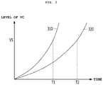
- FIG. 2 is a graph exemplarily illustrating the time taken for the level of voltage charged in a battery to reach the level of stack voltage
- FIG. 3 is a block diagram of a vehicle including a fuel cell according to another exemplary embodiment
- FIG. 4 is a circuit diagram according to an exemplary embodiment of the vehicle shown in FIG. 1 ;
- FIG. 5 is a circuit diagram according to an exemplary embodiment of the vehicle shown in FIG. 3 ;
- FIG. 6 is a flowchart illustrating a battery-charging method according to an exemplary embodiment.
- FIG. 7 is a block diagram of a vehicle according to a second comparative example.
- relational terms such as “first”, “second”, “on/upper part/above” and “under/lower part/below”, are used only to distinguish between one subject or element and another subject or element, without necessarily requiring or involving any physical or logical relationship or sequence between the subjects or elements.
- FIG. 1 is a block diagram of a vehicle 100 A including a fuel cell according to an exemplary embodiment.
- the vehicle 100 A may include a cell stack 110 , a boost converter 120 , a first switching unit 130 , a buck converter 140 , a second switching unit 150 , a battery 160 , and a controller 170 .
- the fuel cell may be, for example, a polymer electrolyte membrane fuel cell (or a proton exchange membrane fuel cell) (PEMFC), which has been studied most extensively as a power source for driving vehicles.
- the fuel cell may include a cell stack 110 .
- the cell stack 110 may include a plurality of unit cells, which are stacked on one another in a first direction. Each unit cell may generate 0.6 volts to 1.0 volts of electricity, on average 0.7 volts of electricity. The number of unit cells may be determined depending on the magnitude of power to be generated in the fuel cell.
- the boost converter 120 bypasses the voltage generated in the cell stack 110 and output therefrom (hereinafter, referred to as “stack voltage”), or converts the level of the stack voltage and outputs the same in response to a first control signal C 1 .
- the stack voltage corresponds to a potential difference between an output terminal (PO shown in FIG. 4 or 5 ) of a positive-electrode side of the cell stack 110 and an output terminal (NO shown in FIG. 4 or 5 ) of a negative-electrode side of the cell stack 110 .
- first voltage the voltage output from the boost converter 120 for convenience of description.
- the first control signal C 1 may be generated by the controller 170 .
- the controller 170 When the level of the voltage charged in the battery 160 has not reached the level of the stack voltage, the controller 170 generates the first control signal C 1 such that the boost converter 120 bypasses the stack voltage.
- the controller 170 performs control such that the boost converter 120 converts the level of the direct-current-type stack voltage and outputs the direct-current-type voltage having the converted level.
- the boost converter 120 may be a direct-current/direct-current converter that boosts the stack voltage and outputs the boosted voltage as the first voltage.
- the boost converter 120 may increase the level of the stack voltage to a level required by the battery 160 or to a level required by a load stage 180 to be described later with reference to FIGS. 4 and 5 .
- the controller 170 may inspect the level of the voltage charged in the battery 160 and may generate the first control signal C 1 according to the result of the inspection.
- the first switching unit 130 may be switched on in response to the first switching signal S 1 , and may form a main path MCP for supplying the first voltage output from the boost converter 120 to the battery 160 .
- the first switching signal S 1 may be generated by the controller 170 .
- the controller 170 may generate the first switching signal S 1 to switch the first switching unit 130 off so that the main path MCP is not formed.
- the controller 170 may generate the first switching signal S 1 to switch the first switching unit 130 on so that the main path MCP is formed. That is, when the first switching unit 130 is switched on, the main path MCP, through which current is capable of flowing from the boost converter 120 to the battery 160 , may be formed.
- the controller 170 may inspect the level of the voltage charged in the battery 160 , and may generate the first switching signal S 1 according to the result of the inspection.
- the buck converter 140 converts the level of the first voltage output from the boost converter 120 and outputs the same to the battery 160 in response to a second control signal C 2 .
- second voltage the voltage output from the buck converter 140 is referred to as “second voltage” for convenience of description.
- the second control signal C 2 may be generated by the controller 170 .
- the controller 170 may generate the second control signal C 2 so that the buck converter 140 converts the level of the stack voltage bypassed from the boost converter 120 .
- the controller 170 stops the operation of the buck converter 140 through the second control signal C 2 .
- the boost converter 120 may increase the level of the stack voltage, whereas the buck converter 140 may decrease the level of the first voltage.
- the controller 170 may inspect the level of the voltage charged in the battery 160 and may generate the second control signal C 2 according to the result of the inspection.
- the second switching unit 150 may be switched in response to the second switching signal S 2 , and may form a bypass path BCP for supplying the second voltage output from the buck converter 140 to the battery 160 .
- the second switching signal S 2 may be generated by the controller 170 .
- the controller 170 may generate the second switching signal S 2 to switch the second switching unit 150 on so that the bypass path BCP is formed.
- the controller 170 may generate the second switching signal S 2 to switch the second switching unit 150 off so that the bypass path BCP is not formed. That is, when the second switching unit 150 is switched on, the bypass path BCP, through which current is capable of flowing from the boost converter 120 to the battery 160 , may be formed.
- the controller 170 may inspect the level of the voltage charged in the battery 160 and may generate the second switching signal S 2 according to the result of the inspection.
- the controller 170 may generate the first and second switching signals S 1 and S 2 such that the first switching unit 130 and the second switching unit 150 are alternately switched.
- the rated power of the buck converter 140 (hereinafter, referred to as “second rated power”) is lower than the rated power of the boost converter 120 (hereinafter, referred to as “first rated power”).
- the current flows to the battery 160 through the bypass path BCP, which is formed by the buck converter 140 , having low rated power, and the second switching unit 150 , rather than flowing through the main path MCP, whereby the boost converter 120 and the battery 160 may be prevented from being damaged.
- the second rated power may be 5% to 10% of the first rated power, but the disclosure is not limited thereto.
- the rated power of the second switching unit 150 (hereinafter, referred to as “third rated power”), which forms the bypass path BCP together with the buck converter 140 , may be 5% to 10% of the first rated power.
- each of the second rated power and the third rated power may be determined according to the time (or the period) required for the level of the voltage charged in the battery 160 to reach the level of the stack voltage.
- FIG. 2 is a graph exemplarily illustrating the time taken for the level of the voltage VC charged in the battery 160 to reach the level VS of the stack voltage, in which the horizontal axis denotes time and the vertical axis denotes the level of the voltage VC charged in the battery 160 .
- a first time T 1 is taken for the level of the voltage VC charged in the battery 160 to reach the level VS of the stack voltage.
- a second time T 2 is taken for the level of the voltage VC charged in the battery 160 to reach the level VS of the stack voltage.
- the values of the second rated power and the third rated power may be increased in order for the level of the voltage VC charged in the battery 160 to reach the level VS of the stack voltage more quickly.
- each of the second rated power and the third rated power may be 10% of the first rated power.
- each of the second rated power and the third rated power may be 5% of the first rated power.
- the disclosure is not limited to any specific ratio of each of the second rated power and the third rated power to the first rated power.
- FIG. 3 is a block diagram of a vehicle 100 B including a fuel cell according to another exemplary embodiment.
- the vehicle 100 B shown in FIG. 3 may include a cell stack 110 , a boost converter 120 , a first switching unit 130 , a buck converter 140 , a second switching unit 150 , a battery 160 , and a controller 170 .
- the vehicle 100 B shown in FIG. 3 is configured such that the second switching unit 150 is disposed between the boost converter 120 and the buck converter 140 . Except for the position at which the second switching unit 150 is disposed, the vehicle 100 B shown in FIG. 3 is the same as the vehicle 100 A shown in FIG. 1 . That is, the cell stack 110 , the boost converter 120 , the first switching unit 130 , the buck converter 140 , the second switching unit 150 , the battery 160 , and the controller 170 shown in FIG.
- FIG. 3 correspond to the cell stack 110 , the boost converter 120 , the first switching unit 130 , the buck converter 140 , the second switching unit 150 , the battery 160 , and the controller 170 shown in FIG. 1 , respectively, and thus a duplicate description thereof will be omitted.
- FIG. 4 is a circuit diagram according to an exemplary embodiment of the vehicle 100 A shown in FIG. 1 .
- the vehicle 100 A shown in FIG. 4 may include a cell stack 110 , a boost converter 120 A, a first switching unit 130 A, a buck converter 140 A, a second switching unit 150 A, a battery 160 , and a controller 170 A.
- the cell stack 110 , the boost converter 120 A, the first switching unit 130 A, the buck converter 140 A, the second switching unit 150 A, the battery 160 , and the controller 170 A shown in FIG. 4 perform the same functions as the cell stack 110 , the boost converter 120 , the first switching unit 130 , the buck converter 140 , the second switching unit 150 , the battery 160 , and the controller 170 shown in FIG. 1 , respectively, and thus a duplicate description thereof will be omitted.
- the boost converter 120 A, the first switching unit 130 A, the buck converter 140 A, the second switching unit 150 A, and the controller 170 A shown in FIG. 4 correspond to the respective embodiments of the boost converter 120 , the first switching unit 130 , the buck converter 140 , the second switching unit 150 , and the controller 170 shown in FIG. 1 .
- the boost converter 120 A may include first and second capacitors CA 1 and CA 2 , a first inductor L 1 , a first diode D 1 , and a first semiconductor switch.
- the first capacitor CA 1 may be disposed between an output terminal PO of a positive-electrode side of the cell stack 110 and an output terminal NO of a negative-electrode side of the cell stack 110 .
- the first inductor L 1 has one end connected to the output terminal PO of the positive-electrode side of the cell stack 110 and the other end connected to the positive electrode of the first diode D 1 . That is, the first inductor L 1 is disposed between the output terminal PO of the positive-electrode side of the cell stack 110 and the positive electrode of the first diode D 1 .
- the first diode D 1 has a positive electrode connected to the other end of the first inductor L 1 .
- the second capacitor CA 2 may be disposed between a negative electrode of the first diode D 1 and the output terminal NO of the negative-electrode side of the cell stack 110 .
- the first and second capacitors CA 1 and CA 2 are smoothing capacitors.
- the first semiconductor switch may be switched on or off in response to the first control signal C 1 , and may be connected to the positive electrode of the first diode D 1 and the output terminal NO of the negative-electrode side of the cell stack 110 while being disposed therebetween.
- the first semiconductor switch may be implemented as an insulated gate bipolar transistor (IGBT) or a field effect transistor (FET).
- IGBT insulated gate bipolar transistor
- FET field effect transistor
- the first semiconductor switch may be implemented as a first transistor SS 1 .
- the first transistor SS 1 may include a gate G connected to the first control signal C 1 , a drain D connected to the positive electrode of the first diode D 1 , and a source S connected to the output terminal NO of the negative-electrode side of the cell stack 110 .
- the first transistor SS 1 which is the first semiconductor switch, may be turned off in response to the first control signal C 1 output from the controller 170 A, and current may flow in the direction indicated by the arrow CP.
- the first transistor SS 1 which is the first semiconductor switch, may be turned on in response to the first control signal C 1 output from the controller 170 A, and the operation of boosting the stack voltage may be performed.
- the first switching unit 130 A may include first and second switches 132 and 134 .
- the first switch 132 may be disposed between the negative electrode of the first diode D 1 and an input terminal PI of a positive-electrode side of the battery 160 , and may be switched on or off in response to a 1-1 st switching signal S 11 .
- the second switch 134 may be disposed between an output terminal NO of a negative-electrode side of the cell stack 110 and an input terminal NI of a negative-electrode side of the battery 160 , and may be switched on or off in response to a 1-2 nd switching signal S 12 .
- the first and second switches 132 and 134 may be switched on at the same time, or may be switched off at the same time. Therefore, the 1-1 st switching signal S 11 and the 1-2 nd switching signal S 12 may be the same signal.
- each of the 1-1 st switching signal S 11 and the 1-2 nd switching signal S 12 corresponds to the first switching signal S 1 described above.
- the buck converter 140 A may include a second inductor L 2 , a second semiconductor switch, and a second diode D 2 .
- the second inductor L 2 may include one end connected to the input terminal PI of the positive-electrode side of the battery 160 via the second switching unit 150 A and the other end connected to the negative electrode of the second diode D 2 . That is, the second inductor L 2 may be disposed between the input terminal PI of the positive-electrode side of the battery 160 and the negative electrode of the second diode D 2 . Also, the second inductor L 2 may be connected to the input terminal PI of the positive-electrode side of the battery 160 and the negative electrode of the second diode D 2 .
- the second semiconductor switch may be switched on or off in response to the second control signal C 2 , and may be connected to the negative electrode of the first diode D 1 and the other end of the second inductor L 2 while being disposed therebetween. Similar to the first semiconductor switch, the second semiconductor switch may also be implemented as an IGBT or an FET. For example, as illustrated in FIG. 4 , the second semiconductor switch may be implemented as a second transistor SS 2 .
- the second transistor SS 2 may include a gate G connected to the second control signal C 2 , a drain D connected to the negative electrode of the first diode D 1 , and a source S connected to the other end of the second inductor L 2 (i.e. the negative electrode of the second diode D 2 ).
- the second diode D 2 may include a negative electrode connected to the other end of the second inductor L 2 and a positive electrode connected to the output terminal NO of the negative-electrode side of the cell stack 110 .
- the second transistor SS 2 which is the second semiconductor switch, may be turned on in response to the second control signal C 2 output from the controller 170 A.
- the second transistor SS 2 which is the second semiconductor switch, may be turned off in response to the second control signal C 2 output from the controller 170 A.
- the bypass path BCP may not be formed, and when the main path MCP is not formed, the bypass path BCP may be formed.
- the fact that the first rated power of the boost converter 120 and 120 A is higher than the second rated power of the buck converter 140 and 140 A means that the first inductor L 1 and the first diode D 1 , which are included in the boost converter 120 A, withstand higher current without being damaged than the second inductor L 2 and the second diode D 2 , which are included in the buck converter 140 A.
- the second inductor L 2 and the second diode D 2 may be capable of withstanding only about 5% to 10% of the level of the current that the first inductor L 1 and the first diode D 1 may be capable of withstanding.
- the second switching unit 150 A may include third and fourth switches 152 and 154 .
- the third switch 152 may be disposed between one end of the second inductor L 2 and the input terminal PI of the positive-electrode side of the battery 160 , and may be switched on or off in response to a 2-1 st switching signal S 21 .
- the fourth switch 154 may be disposed between the positive electrode of the second diode D 2 and the input terminal NI of the negative-electrode side of the battery 160 , and may be switched on or off in response to a 2-2 nd switching signal S 22 .
- the third and fourth switches 152 and 154 may be switched on at the same time, or may be switched off at the same time. Therefore, the 2-1 st switching signal S 21 and the 2-2 nd switching signal S 22 may be the same signal. Each of the 2-1 st switching signal S 21 and the 2-2 nd switching signal S 22 corresponds to the second switching signal S 2 described above.
- the fact that the first rated power of the boost converter 120 and 120 A is higher than the third rated power of the second switching unit 150 A means that the first inductor L 1 and the first diode D 1 , which are included in the boost converter 120 A, are capable of withstanding higher current without being damaged than the third and fourth switches 152 and 154 , which are included in the second switching unit 150 A.
- the third and fourth switches 152 and 154 may be capable of withstanding only about 5% to 10% of the level of the current that the first inductor L 1 and the first diode D 1 may be capable of withstanding.
- FIG. 5 is a circuit diagram according to an exemplary embodiment of the vehicle 100 B shown in FIG. 3 .
- the vehicle 100 B shown in FIG. 5 may include a cell stack 110 , a boost converter 120 A, a first switching unit 130 A, a buck converter 140 A, a second switching unit 150 B, a battery 160 , and a controller 170 A.
- the vehicle 100 B shown in FIG. 5 is configured such that the second switching unit 150 B is disposed between the boost converter 120 A and buck converter 140 A. Except for this difference, the vehicle 100 B shown in FIG. 5 is the same as the vehicle 100 A shown in FIG. 4 , and thus a duplicate description thereof will be omitted. Therefore, only the second switching unit 150 B shown in FIG. 5 , which is disposed at a position different from that shown in FIG. 4 , will be described below.
- the second switching unit 150 B may include fifth and sixth switches 156 and 158 .
- the fifth switch 156 may be disposed between the negative electrode of the first diode D 1 and the drain D of the second transistor SS 2 , which is the second semiconductor switch, and may be switched on or off in response to the 2-1 st switching signal S 21 .
- the sixth switch 158 may be disposed between the output terminal NO of the negative-electrode side of the cell stack 110 and the positive electrode of the second diode D 2 , and may be switched on or off in response to the 2-2 nd switching signal S 22 .
- the fifth and sixth switches 156 and 158 may be switched on at the same time or may be switched off at the same time. Therefore, the 2-1 st switching signal S 21 and the 2-2 nd switching signal S 22 may be the same signal. Each of the 2-1 st switch signal S 21 and the 2-2 nd switching signal S 22 corresponds to the second switching signal S 2 described above.
- At least one of the first and second switches 132 and 134 which are included in the first switching unit 120 A shown in FIGS. 4 and 5 , the third and fourth switches 152 and 154 , which are included in the second switching unit 150 A shown in FIG. 4 , or the fifth and sixth switches 156 and 158 , which are included in the second switching unit 150 B shown in FIG. 5 , may include a relay, a semiconductor switch, or a diode.
- the disclosure is not limited to any specific form of each of the first to sixth switches 132 , 134 , 152 , 154 , 156 and 158 .
- each of the first and second switches 132 and 134 may be switched on, and when a first switching signal S 1 having a “low” level (e.g. 0 volts) is supplied from the controller 170 and 170 A, each of the first and second switches 132 and 134 may be switched off.
- a first switching signal S 1 having a “high” level e.g. 12 volts
- a first switching signal S 1 having a “low” level e.g. 0 volts
- each of the third to sixth switches 152 , 154 , 156 and 158 may be switched on, and when a second switching signal S 2 having a “low” level (e.g. 0 volts) is supplied from the controller 170 and 170 A, each of the third to sixth switches 152 , 154 , 156 and 158 may be switched off.
- a second switching signal S 2 having a “high” level e.g. 12 volts
- a second switching signal S 2 having a “low” level e.g. 0 volts
- the vehicle 100 A and 100 B including a fuel cell according to the embodiment may further include a load stage 180 , as shown in FIGS. 4 and 5 .
- the load stage 180 may be connected to the main path MCP to receive the first voltage output from the boost converter 120 A. Alternatively, regardless of the formation of the main path MCP by the first switching unit 130 A, the load stage 180 may receive the voltage charged in the battery 160 .
- the load stage 180 may include an inverter 182 and a motor 184 .
- the inverter 182 is connected to the input terminal PI of the positive-electrode side of the battery 160 and the input terminal NI of the negative-electrode side of the battery 160 .
- the inverter 182 converts the direct-current-type first voltage supplied thereto or the direct-current-type voltage charged in the battery 160 into alternating-current-type voltage, and outputs the alternating-current-type voltage to the motor 184 according to the driving state of the vehicle 100 A and 100 B.
- the motor 184 may be driven in response to the alternating-current-type voltage output from the inverter 182 . That is, the motor 184 may rotate by receiving the alternating-current-type voltage for the motor from the inverter 182 , and may propel the vehicle 100 A and 100 B.
- the motor 184 may be a three-phase AC rotating device including a rotor having a permanent magnet embedded therein.
- the disclosure is not limited to any specific form of the motor 184 .
- the load stage 180 of the vehicle 100 A and 100 B may include components required for driving the vehicle, such as motor-driven power steering (MDPS), a radiator fan, headlights, and the like.
- MDPS motor-driven power steering
- Each of the various loads included in the load stage 180 may be driven by receiving the first voltage or the voltage charged in the battery 160 as driving voltage.
- FIG. 6 is a flowchart illustrating a battery-charging method 200 according to an exemplary embodiment.
- the battery-charging method 200 according to the embodiment shown in FIG. 6 may be performed in the vehicle 100 A and 100 B shown in FIG. 1, 3, 4 or 5 , but the disclosure is not limited thereto. That is, according to another exemplary embodiment, the battery-charging method 200 according to the embodiment shown in FIG. 6 may also be performed in a vehicle including a fuel cell, which has a different configuration from the vehicle 100 A and 100 B shown in FIG. 1, 3, 4 or 5 .
- the controller 170 and 170 A of the vehicle 100 A and 100 B shown in FIG. 1, 3, 4 or 5 may perform the battery-charging method 200 according to the embodiment shown in FIG. 6 , but the disclosure is not limited thereto. That is, according to another exemplary embodiment, the controller 170 and 170 A of the vehicle 100 A and 100 B shown in FIG. 1, 3, 4 or 5 may perform a battery-charging method having a process different from the battery-charging method 200 according to the embodiment shown in FIG. 6 .
- the level of the voltage charged in the battery 160 is inspected (step 210 ).
- step 210 whether the inspected level of the voltage charged in the battery 160 has reached the level of the stack voltage is determined (step 220 ).
- the bypass path BCP is formed to supply the second voltage, formed by converting the level of the first voltage bypassed from the boost converter 120 and 120 A, to the battery 160 (step 230 ), and the procedure returns to step 220 .
- the controller 170 and 170 A switches the first switching unit 130 and 130 A off using the first switching signal S 1 , and switches the second switching unit 150 , 150 A and 150 B on using the second switching signal S 2 .
- the main path MCP is formed to supply the first voltage, the level of which is converted by the boost converter 120 and 120 A, to the battery 160 (step 240 ).
- the controller 170 and 170 A switches the first switching unit 130 and 130 A on using the first switching signal S 1 , and switches the second switching unit 150 , 150 A and 150 B off using the second switching signal S 2 .
- a vehicle includes various kinds of electronic control units (ECUs).
- An ECU is a kind of computer having therein software capable of performing various functions for a vehicle.
- the battery-charging method 200 according to the embodiment described above may be executed by an ECU.
- a recording medium on which a program for executing the battery-charging method 200 , which is performed in the vehicle 100 A and 100 B including a fuel cell, is recorded may have stored thereon a program for implementing a function of determining whether the level of the voltage charged in the battery 160 has reached the level of the stack voltage, a function of forming the bypass path to supply the second voltage to the battery 160 when the level of the voltage charged in the battery 160 has not reached the level of the stack voltage, and a function of forming the main path to supply the first voltage to the battery 160 when the level of the voltage charged in the battery 160 reaches the level of the stack voltage.
- the recording medium may be read by a computer.
- the computer-readable recording medium includes all kinds of recording devices in which data that may be read by a computer system are stored. Examples of the computer-readable recording medium may include ROM, RAM, a CD-ROM, a magnetic tape, a floppy disk, and an optical data storage device.
- the computer-readable recording medium may also be distributed over network-coupled computer systems so that the computer-readable code is stored and executed by e.g., a processor, in a distributed fashion. Also, functional programs, code, and code segments for accomplishing the battery-charging method may be easily devised by programmers skilled in the art to which the present disclosure pertains.
- the aforementioned controllers may be a processor (e.g., computer, microprocessor, CPU, ASIC, circuitry, logic circuits, etc.).
- the controllers may be implemented by a non-transitory memory storing, e.g., a program(s), software instructions reproducing algorithms, etc., which, when executed, controls operations of various components of the vehicle, and a processor configured to execute the program(s), software instructions reproducing algorithms, etc.
- the memory and the processor may be implemented as separate semiconductor circuits.
- the memory and the processor may be implemented as a single integrated semiconductor circuit.
- the processor may embody one or more processor(s).
- a vehicle according to a first comparative example is the same as the vehicle 100 A and 100 B according to the embodiment, except that it does not include the buck converter 140 or the second switching unit 150 shown in FIGS. 1, 3, 4 and 5 .
- the first semiconductor switch SS 1 is in the off state in the boost converter 120 and 120 A until the level of the voltage charged in the battery 160 reaches the level of the stack voltage, and thus current flows through the first diode D 1 in the direction indicated by the arrow CP, as shown in FIG. 4 .
- a very large level of current may flow in the direction indicated by the arrow CP in the state in which the boost converter 120 and 120 A is short-circuited. Therefore, in the case of the vehicle according to the first comparative example, the internal elements CA 1 , L 1 , D 1 and CA 2 of the boost converter 120 and 120 A, particularly the first diode D 1 , may burn out, and the battery 160 may be damaged.
- FIG. 7 is a block diagram of a vehicle 10 according to a second comparative example.
- the vehicle 10 according to the second comparative example shown in FIG. 7 includes a cell stack 12 , a boost converter 20 , a first switching unit 30 , a buck converter 40 , a battery 60 , and a controller 70 .
- the cell stack 12 , the boost converter 20 , the first switching unit 30 , the buck converter 40 , the battery 60 , and the controller 70 perform the same functions and have the same configurations as the cell stack 110 , the boost converter 120 , the first switching unit 130 , the buck converter 140 , the battery 160 , and the controller 170 , respectively, of the vehicle 100 A and 100 B according to exemplary embodiments of the present disclosure. Therefore, first and second control signals C 1 and C 2 and a first switching signal S 1 shown in FIG. 7 perform the same functions as the first and second control signals C 1 and C 2 and the first switching signal S 1 shown in FIGS. 4 and 5 , respectively.
- the buck converter 40 is disposed between the first switching unit 30 and the battery 60 in order to prevent the battery 60 and internal elements of the boost converter 20 from being damaged in the state in which the voltage charged in the battery 60 has not reached the stack voltage.
- the buck converter 40 is disposed in the path through which power from the cell stack 12 is charged into the battery 60 . Therefore, when the battery 60 is charged with power, the power inevitably passes through the buck converter 40 , which may lead to deterioration in power-charging efficiency.
- the buck converter 40 shown in FIG. 7 is absent from the path through which power from the cell stack 110 is charged into the battery 160 , thereby exhibiting improved power-charging efficiency compared to the second comparative example.
- a process of transmitting driving energy from the cell stack 12 to a load stage may be the same as that in the vehicle 100 A and 100 B according to the embodiment.
- the buck converter 40 is disposed in the path through which driving energy is transmitted from the battery 60 to a load stage (not shown). Therefore, when energy charged in the battery 60 is supplied to the load stage, the energy inevitably passes through the buck converter 40 , which may lead to deterioration in efficiency of utilization of charged power.
- the power charged in the battery 160 is directly supplied to the load stage 180 , rather than passing through the buck converter 40 , thereby exhibiting improved efficiency of utilization of charged power compared to the second comparative example.
- no buck converter is disposed in a path through which power from a cell stack is charged into the battery, unlike the second comparative example, thereby exhibiting improved power-charging efficiency compared to the second comparative example.
Landscapes
- Engineering & Computer Science (AREA)
- Power Engineering (AREA)
- Transportation (AREA)
- Mechanical Engineering (AREA)
- Life Sciences & Earth Sciences (AREA)
- Sustainable Development (AREA)
- Sustainable Energy (AREA)
- Chemical & Material Sciences (AREA)
- Combustion & Propulsion (AREA)
- Electric Propulsion And Braking For Vehicles (AREA)
- Dc-Dc Converters (AREA)
Abstract
Description
Claims (19)
Applications Claiming Priority (2)
| Application Number | Priority Date | Filing Date | Title |
|---|---|---|---|
| KR10-2020-0003072 | 2020-01-09 | ||
| KR1020200003072A KR102676247B1 (en) | 2020-01-09 | 2020-01-09 | Vehicle including fuel cell, method for charging battery performed in the vehicle, and recording medium for recording program performing the method |
Publications (2)
| Publication Number | Publication Date |
|---|---|
| US20210213842A1 US20210213842A1 (en) | 2021-07-15 |
| US11505075B2 true US11505075B2 (en) | 2022-11-22 |
Family
ID=76708977
Family Applications (1)
| Application Number | Title | Priority Date | Filing Date |
|---|---|---|---|
| US17/035,183 Active 2041-01-28 US11505075B2 (en) | 2020-01-09 | 2020-09-28 | Vehicle including fuel cell, battery-charging method for the vehicle, and recording medium having recorded therein program for executing the method |
Country Status (3)
| Country | Link |
|---|---|
| US (1) | US11505075B2 (en) |
| KR (1) | KR102676247B1 (en) |
| CN (1) | CN113103926B (en) |
Cited By (1)
| Publication number | Priority date | Publication date | Assignee | Title |
|---|---|---|---|---|
| US20220166339A1 (en) * | 2020-11-23 | 2022-05-26 | Richtek Technology Corporation | High efficiency charging system and power conversion circuit thereof |
Families Citing this family (6)
| Publication number | Priority date | Publication date | Assignee | Title |
|---|---|---|---|---|
| US12587021B2 (en) * | 2021-09-15 | 2026-03-24 | Halo Microelectronics International | Versatile battery charging system and control method |
| CN113890371B (en) * | 2021-09-30 | 2023-11-24 | 康舒科技股份有限公司 | Multi-output power distribution control device |
| US12431720B2 (en) | 2021-11-09 | 2025-09-30 | Samsung Electronics Co., Ltd. | Charger integrated circuit for charging series battery device and electronic device including same |
| CN114701375B (en) * | 2021-11-12 | 2023-07-07 | 上海汽车集团股份有限公司 | A kind of electric vehicle charging system and electric vehicle |
| KR102911851B1 (en) * | 2021-12-16 | 2026-01-14 | 현대자동차주식회사 | Fuel cell apparatus |
| CN114689970B (en) * | 2022-03-24 | 2025-01-17 | 联合汽车电子有限公司 | Shutdown path detection method, circuit and storage medium for DCDC converter |
Citations (9)
| Publication number | Priority date | Publication date | Assignee | Title |
|---|---|---|---|---|
| JP2000036308A (en) | 1998-07-16 | 2000-02-02 | Toyota Motor Corp | Fuel cell system |
| US20030234634A1 (en) * | 2002-06-25 | 2003-12-25 | Young-Kook Lee | Method and system for diagnosing an arm-short of a bi-directional DC/DC converter |
| JP2009165243A (en) | 2007-12-28 | 2009-07-23 | Toyota Motor Corp | Fuel cell system |
| KR101039679B1 (en) | 2009-11-17 | 2011-06-09 | 현대자동차주식회사 | Mild hybrid system and method controlling thereof |
| US20120112684A1 (en) * | 2010-09-30 | 2012-05-10 | Yang Xu | Control system and control method of a solar power supply |
| JP5326228B2 (en) | 2006-09-04 | 2013-10-30 | トヨタ自動車株式会社 | Fuel cell system |
| US20140302415A1 (en) * | 2013-03-15 | 2014-10-09 | Ford Global Technologies, Llc | Apparatus and method for heating a fuel cell stack |
| JP2017091882A (en) | 2015-11-12 | 2017-05-25 | 日産自動車株式会社 | Power adjusting system |
| US20180026463A1 (en) * | 2016-07-21 | 2018-01-25 | GM Global Technology Operations LLC | Apparatus and method to apply voltage to fuel cell stack from high voltage system for usage during diagnostic tests |
Family Cites Families (10)
| Publication number | Priority date | Publication date | Assignee | Title |
|---|---|---|---|---|
| US8373381B2 (en) * | 2005-04-22 | 2013-02-12 | GM Global Technology Operations LLC | DC/DC-less coupling of matched batteries to fuel cells |
| JP4561827B2 (en) * | 2007-12-28 | 2010-10-13 | トヨタ自動車株式会社 | Fuel cell system and boost converter for fuel cell |
| JP2013101844A (en) * | 2011-11-09 | 2013-05-23 | Toyota Motor Corp | Fuel cell system and control method for the same |
| CN107215223B (en) * | 2015-09-16 | 2020-06-12 | 唐棣 | Fuel cell hybrid electric vehicle system |
| JP6330822B2 (en) * | 2016-01-14 | 2018-05-30 | トヨタ自動車株式会社 | Fuel cell system and control method thereof |
| CN109155531B (en) * | 2016-07-22 | 2022-04-29 | 株式会社村田制作所 | Battery device, electronic device, electric vehicle, power storage system, and control method |
| US10486543B2 (en) * | 2016-10-25 | 2019-11-26 | Toyota Jidosha Kabushiki Kaisha | Voltage control device for fuel-cell vehicle |
| KR101905997B1 (en) * | 2016-11-09 | 2018-10-08 | 현대자동차주식회사 | Charging apparatus in vehicle |
| DE102017210800A1 (en) * | 2017-06-27 | 2018-12-27 | Mahle International Gmbh | Method for cooling a fuel cell and a cooling system |
| KR102449850B1 (en) * | 2017-07-12 | 2022-10-04 | 현대자동차주식회사 | Pre-charge relay control system for fuel cell vehicle and control method of the same |
-
2020
- 2020-01-09 KR KR1020200003072A patent/KR102676247B1/en active Active
- 2020-09-28 US US17/035,183 patent/US11505075B2/en active Active
- 2020-11-11 CN CN202011257118.4A patent/CN113103926B/en active Active
Patent Citations (9)
| Publication number | Priority date | Publication date | Assignee | Title |
|---|---|---|---|---|
| JP2000036308A (en) | 1998-07-16 | 2000-02-02 | Toyota Motor Corp | Fuel cell system |
| US20030234634A1 (en) * | 2002-06-25 | 2003-12-25 | Young-Kook Lee | Method and system for diagnosing an arm-short of a bi-directional DC/DC converter |
| JP5326228B2 (en) | 2006-09-04 | 2013-10-30 | トヨタ自動車株式会社 | Fuel cell system |
| JP2009165243A (en) | 2007-12-28 | 2009-07-23 | Toyota Motor Corp | Fuel cell system |
| KR101039679B1 (en) | 2009-11-17 | 2011-06-09 | 현대자동차주식회사 | Mild hybrid system and method controlling thereof |
| US20120112684A1 (en) * | 2010-09-30 | 2012-05-10 | Yang Xu | Control system and control method of a solar power supply |
| US20140302415A1 (en) * | 2013-03-15 | 2014-10-09 | Ford Global Technologies, Llc | Apparatus and method for heating a fuel cell stack |
| JP2017091882A (en) | 2015-11-12 | 2017-05-25 | 日産自動車株式会社 | Power adjusting system |
| US20180026463A1 (en) * | 2016-07-21 | 2018-01-25 | GM Global Technology Operations LLC | Apparatus and method to apply voltage to fuel cell stack from high voltage system for usage during diagnostic tests |
Cited By (2)
| Publication number | Priority date | Publication date | Assignee | Title |
|---|---|---|---|---|
| US20220166339A1 (en) * | 2020-11-23 | 2022-05-26 | Richtek Technology Corporation | High efficiency charging system and power conversion circuit thereof |
| US12348153B2 (en) * | 2020-11-23 | 2025-07-01 | Richtek Technology Corporation | High efficiency charging system and power conversion circuit thereof |
Also Published As
| Publication number | Publication date |
|---|---|
| CN113103926A (en) | 2021-07-13 |
| US20210213842A1 (en) | 2021-07-15 |
| KR102676247B1 (en) | 2024-06-20 |
| CN113103926B (en) | 2026-03-10 |
| KR20210090320A (en) | 2021-07-20 |
Similar Documents
| Publication | Publication Date | Title |
|---|---|---|
| US20210213842A1 (en) | Vehicle including fuel cell, battery-charging method for the vehicle, and recording medium having recorded therein program for executing the method | |
| US12090875B2 (en) | Multi-input charging system and method using a motor driving device | |
| US7728562B2 (en) | Voltage link control of a DC-AC boost converter system | |
| US8299739B2 (en) | Motor drive | |
| US11390179B2 (en) | Vehicle and method for controlling thereof | |
| US10651772B2 (en) | Inverter system for vehicle and control method thereof | |
| CN102195330B (en) | Battery charging circuit and charging method | |
| KR20230119441A (en) | System of charging battery for vehicle using motor driving system | |
| CN110034318B (en) | Fuel cell system and control method of fuel cell system | |
| CN101722906B (en) | Electrical system and automotive drive system having an on-demand boost converter, and related operating methods | |
| JP2020010517A (en) | Charge control device and charge control system | |
| US20220410741A1 (en) | System for charging vehicle battery using motor driving system | |
| US12617300B2 (en) | Integrated vehicle power converter and battery charger | |
| US20250196653A1 (en) | Electrical circuit and storage medium | |
| CN116587895B (en) | A charging and electric drive control system and its control method | |
| US12597618B2 (en) | Fuel cell vehicle, method of controlling startup thereof, and recording medium storing program to execute the method | |
| JP2020048301A (en) | Power converter | |
| JP2023181682A (en) | Power control device and power control method | |
| JP2022160202A (en) | Power conversion device | |
| JP7010117B2 (en) | Motor system | |
| US20250042269A1 (en) | Power control apparatus for fuel cell vehicle, power control method thereof, and power system for fuel cell vehicle including the power control apparatus | |
| US20250319777A1 (en) | Electric vehicle | |
| US20250211018A1 (en) | Charging system | |
| US20250196691A1 (en) | Electric circuit and non-transitory storage medium | |
| JP7455735B2 (en) | fuel cell system |
Legal Events
| Date | Code | Title | Description |
|---|---|---|---|
| FEPP | Fee payment procedure |
Free format text: ENTITY STATUS SET TO UNDISCOUNTED (ORIGINAL EVENT CODE: BIG.); ENTITY STATUS OF PATENT OWNER: LARGE ENTITY |
|
| AS | Assignment |
Owner name: HYUNDAI MOTOR COMPANY, KOREA, REPUBLIC OF Free format text: ASSIGNMENT OF ASSIGNORS INTEREST;ASSIGNORS:LEE, WOO YOUNG;KIM, JU HAN;REEL/FRAME:053911/0841 Effective date: 20200915 Owner name: KIA MOTORS CORPORATION, KOREA, REPUBLIC OF Free format text: ASSIGNMENT OF ASSIGNORS INTEREST;ASSIGNORS:LEE, WOO YOUNG;KIM, JU HAN;REEL/FRAME:053911/0841 Effective date: 20200915 |
|
| STPP | Information on status: patent application and granting procedure in general |
Free format text: DOCKETED NEW CASE - READY FOR EXAMINATION |
|
| STPP | Information on status: patent application and granting procedure in general |
Free format text: NON FINAL ACTION MAILED |
|
| STPP | Information on status: patent application and granting procedure in general |
Free format text: RESPONSE TO NON-FINAL OFFICE ACTION ENTERED AND FORWARDED TO EXAMINER |
|
| STPP | Information on status: patent application and granting procedure in general |
Free format text: NOTICE OF ALLOWANCE MAILED -- APPLICATION RECEIVED IN OFFICE OF PUBLICATIONS |
|
| STCF | Information on status: patent grant |
Free format text: PATENTED CASE |
|
| MAFP | Maintenance fee payment |
Free format text: PAYMENT OF MAINTENANCE FEE, 4TH YEAR, LARGE ENTITY (ORIGINAL EVENT CODE: M1551); ENTITY STATUS OF PATENT OWNER: LARGE ENTITY Year of fee payment: 4 |