US11502463B2 - Connection apparatus with variable electrical connection between conductor terminals - Google Patents
Connection apparatus with variable electrical connection between conductor terminals Download PDFInfo
- Publication number
- US11502463B2 US11502463B2 US16/623,566 US201816623566A US11502463B2 US 11502463 B2 US11502463 B2 US 11502463B2 US 201816623566 A US201816623566 A US 201816623566A US 11502463 B2 US11502463 B2 US 11502463B2
- Authority
- US
- United States
- Prior art keywords
- housing
- plug
- contacts
- conductor terminals
- connection apparatus
- Prior art date
- Legal status (The legal status is an assumption and is not a legal conclusion. Google has not performed a legal analysis and makes no representation as to the accuracy of the status listed.)
- Active
Links
- 239000004020 conductor Substances 0.000 title claims abstract description 53
- 230000000717 retained effect Effects 0.000 claims description 3
- 230000037431 insertion Effects 0.000 claims 2
- 238000003780 insertion Methods 0.000 claims 2
- 238000010586 diagram Methods 0.000 description 3
- 239000002184 metal Substances 0.000 description 2
- 230000007935 neutral effect Effects 0.000 description 2
- 238000005192 partition Methods 0.000 description 2
- 239000000463 material Substances 0.000 description 1
- 238000005457 optimization Methods 0.000 description 1
- 210000002105 tongue Anatomy 0.000 description 1
Images


Classifications
-
- H—ELECTRICITY
- H01—ELECTRIC ELEMENTS
- H01R—ELECTRICALLY-CONDUCTIVE CONNECTIONS; STRUCTURAL ASSOCIATIONS OF A PLURALITY OF MUTUALLY-INSULATED ELECTRICAL CONNECTING ELEMENTS; COUPLING DEVICES; CURRENT COLLECTORS
- H01R29/00—Coupling parts for selective co-operation with a counterpart in different ways to establish different circuits, e.g. for voltage selection, for series-parallel selection, programmable connectors
-
- H—ELECTRICITY
- H01—ELECTRIC ELEMENTS
- H01R—ELECTRICALLY-CONDUCTIVE CONNECTIONS; STRUCTURAL ASSOCIATIONS OF A PLURALITY OF MUTUALLY-INSULATED ELECTRICAL CONNECTING ELEMENTS; COUPLING DEVICES; CURRENT COLLECTORS
- H01R13/00—Details of coupling devices of the kinds covered by groups H01R12/70 or H01R24/00 - H01R33/00
- H01R13/46—Bases; Cases
- H01R13/502—Bases; Cases composed of different pieces
-
- H—ELECTRICITY
- H01—ELECTRIC ELEMENTS
- H01R—ELECTRICALLY-CONDUCTIVE CONNECTIONS; STRUCTURAL ASSOCIATIONS OF A PLURALITY OF MUTUALLY-INSULATED ELECTRICAL CONNECTING ELEMENTS; COUPLING DEVICES; CURRENT COLLECTORS
- H01R9/00—Structural associations of a plurality of mutually-insulated electrical connecting elements, e.g. terminal strips or terminal blocks; Terminals or binding posts mounted upon a base or in a case; Bases therefor
- H01R9/22—Bases, e.g. strip, block, panel
- H01R9/24—Terminal blocks
- H01R9/2491—Terminal blocks structurally associated with plugs or sockets
-
- H—ELECTRICITY
- H01—ELECTRIC ELEMENTS
- H01H—ELECTRIC SWITCHES; RELAYS; SELECTORS; EMERGENCY PROTECTIVE DEVICES
- H01H1/00—Contacts
- H01H1/12—Contacts characterised by the manner in which co-operating contacts engage
- H01H1/36—Contacts characterised by the manner in which co-operating contacts engage by sliding
- H01H1/365—Bridging contacts
-
- H—ELECTRICITY
- H01—ELECTRIC ELEMENTS
- H01H—ELECTRIC SWITCHES; RELAYS; SELECTORS; EMERGENCY PROTECTIVE DEVICES
- H01H15/00—Switches having rectilinearly-movable operating part or parts adapted for actuation in opposite directions, e.g. slide switch
- H01H15/02—Details
- H01H15/06—Movable parts; Contacts mounted thereon
-
- H—ELECTRICITY
- H01—ELECTRIC ELEMENTS
- H01H—ELECTRIC SWITCHES; RELAYS; SELECTORS; EMERGENCY PROTECTIVE DEVICES
- H01H19/00—Switches operated by an operating part which is rotatable about a longitudinal axis thereof and which is acted upon directly by a solid body external to the switch, e.g. by a hand
- H01H19/46—Switches operated by an operating part which is rotatable about a longitudinal axis thereof and which is acted upon directly by a solid body external to the switch, e.g. by a hand the operating part having three operative positions, e.g. off/star/delta
-
- H—ELECTRICITY
- H01—ELECTRIC ELEMENTS
- H01R—ELECTRICALLY-CONDUCTIVE CONNECTIONS; STRUCTURAL ASSOCIATIONS OF A PLURALITY OF MUTUALLY-INSULATED ELECTRICAL CONNECTING ELEMENTS; COUPLING DEVICES; CURRENT COLLECTORS
- H01R4/00—Electrically-conductive connections between two or more conductive members in direct contact, i.e. touching one another; Means for effecting or maintaining such contact; Electrically-conductive connections having two or more spaced connecting locations for conductors and using contact members penetrating insulation
- H01R4/28—Clamped connections, spring connections
- H01R4/48—Clamped connections, spring connections utilising a spring, clip, or other resilient member
- H01R4/4809—Clamped connections, spring connections utilising a spring, clip, or other resilient member using a leaf spring to bias the conductor toward the busbar
- H01R4/48185—Clamped connections, spring connections utilising a spring, clip, or other resilient member using a leaf spring to bias the conductor toward the busbar adapted for axial insertion of a wire end
Definitions
- the invention relates to a connection apparatus for connecting electrical devices.
- a generic connection apparatus is known from DE 2010 012 519 U1.
- phase-strands of the three-phase motor are connected in series so that one end of a phase-strand is connected to the beginning of the next phase-strand.
- connection apparatus in which the interconnection of the multiple conductors is easily altered between at least two different states.
- DE 2010 012 519 U1 provides a configuration plug for the conductive connection of one or more of the multiple terminals in at least two different positions to obtain at least two different types of circuits.
- the configuration plug is preferably set from the outside of a housing of the connection apparatus and rotated to change the circuit position.
- connection apparatus for connecting electrical devices such as electric motors to an AC system.
- the connection apparatus includes a housing that has at least one housing portion in which a plurality of first and second conductor terminals are arranged, each conductor terminal having at least one or two or more individual terminals, and having a configuration plug for the conductive connection of one or more of the first and/or second conductor terminals in at least two different positions to obtain at least two different types of circuits.
- the configuration plug is rotatably and/or slidably guided in or on the housing or at least on the at least one housing portion relative thereto, and due to this relative movement, it can be rotated and/or slid into at least two different rotation and/or sliding positions in order to obtain at least two different types of circuits.
- the configuration plug is retained on or in the housing or at least on or in a portion of the housing and its operation is further simplified so that operating errors or problems due to a loss of configuration plugs can be excluded.
- contacts are formed on the configuration plug for contact with corresponding contacts of the conductor terminals in such a manner that with the configuration plug, one or more of the first and/or the second conductor terminals are conductively connected to one another.
- the conductive connection is such that when connecting a device such as an AC electric motor, a star connection is provided as a first type of circuit in the first rotational and/or sliding position and a delta connection is provided as a second type of circuit in the second rotational and/or sliding position of the configuration plug.
- the configuration plug can be rotatably and/or slidably arranged in or on the housing, for example, in a straight or ring-segment-shaped or circular-segment-shaped groove or the like.
- the configuration plug may also be slidable or rotatable on a rotary bearing in order to be able to move it into the various configurations for a delta connection and a star connection.
- the movement of the configuration plugs can be a pure linear sliding movement or a pure rotation movement or a combined or superimposed sliding and rotation movement according to different embodiments.
- the configuration plug may be arranged in the housing such as between the cover and a lower portion. However, it can protrude with an extension such as a handle extension from the housing.
- the housing includes the first housing portion and the configuration plug forms a further housing portion which is rotatable and/or slidable relative thereto and thus provides a housing function.
- the configuration plug can thus also form a housing portion itself, i.e., it can form the cover which is movably guided on the lower housing portion with the conductor terminals or a cover for opening the lower housing portion on which it can be rotated or slid, or the lower housing portion.
- the lower housing portion can then be rotated and/or slid relative to the cover including the conductor terminals.
- the contacts of the configuration plugs are then arranged in the lower housing portion. This is movable relative to the cover with the conductor terminals relatively slidable.
- the cover is then the housing portion to which the configuration plug, as a lower housing portion, is relatively movable.
- the configuration plug is then slidably and/or rotatably guided on the housing portion and serves as another housing portion.
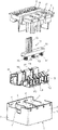
- FIG. 1 is an exploded view of an embodiment of a connection apparatus according to the invention
- FIGS. 2 a and 2 b are perspective and exploded views, respectively, of a connection plug of the connection apparatus of FIG. 1 ;
- FIGS. 3 a and 3 b are top plan views of the connection apparatus of FIG. 1 in first and second configurations, respectively;
- FIGS. 4 a and 4 b are bottom perspective views of a metal subassembly and the connection plug of the connection apparatus of FIG. 1 in the first and second configurations, respectively;
- FIGS. 5 a and 5 b are bottom plan views of the components of FIG. 4 in the first and second configurations, respectively;
- FIGS. 6 a and 6 b are schematic diagrams illustrating the function and structure of the connection apparatus of FIG. 1 in the first and second configurations, respectively;
- FIGS. 7 a and 7 b are schematic diagrams illustrating the function and structure of a further embodiment of the connection apparatus of FIG. 1 in the first and second configurations, respectively;
- FIGS. 8 a , 8 b , and 8 c are schematic diagrams illustrating the function and structure of another embodiment of the connection apparatus of FIG. 1 in delta, neutral and star configurations, respectively.
- the connection apparatus of FIGS. 1 to 6 is used for connecting electrical devices, in particular electric motors, to an AC system. It has a housing 1 , which preferably has a lower housing portion 2 and an upper housing portion or cover 3 which can be placed on the lower housing portion 2 .
- the housing 1 is a separate housing. However, the housing 1 can also be attached to or integrally formed with another—higher-level—housing.
- the cover 3 can be latched to the lower housing portion 2 .
- the lower housing portion 2 has a base 4 and side walls 5 as well as partition walls 6 , which define chambers 7 in which in the example shown, three first single or multiple conductor terminals W 1 , V 1 , U 1 and three second single or multiple conductor terminals V 2 , U 2 , W 2 are arranged.
- corresponding contours or partition walls are also formed in order to define the chambers 7 .
- At least three first conductor terminals W 1 , V 1 , U 1 and at least three second conductor terminals V 2 , U 2 , W 2 are provided in the illustrated embodiments. These can be designed to connect a single conductor end or to connect several conductor ends. In this way, several devices such as motors or the like can be connected.
- openings 8 are formed in the cover 3 .
- openings 9 for releasing the conductors from the conductor terminals W 1 , V 2 , U 1 , V 2 , U 2 , W 2 using tools such as screwdrivers or actuators are provided on the housings 1 , in particular on its covers 3 .
- the first conductor terminals W 1 , V 1 and U 1 are each designed in a preferred embodiment for the connection of three conductor ends.
- the second conductor terminals V 2 , U 2 , W 2 are designed for the connection of one or two conductor ends.
- individual conductor terminals are also designed as single or multiple direct plug-in connections (push-in connections), each with a clamping spring 10 and a busbar 11 .
- Each terminal may further be provided with a clamping cage which may be formed from the busbars 11 .
- the first and/or second conductor terminals W 1 , V, U 1 ; V 2 , U 2 , W 2 can also be designed with other connection configurations such as screw-connections or spring-cage connections.
- a configuration plug 12 is also slidably guided.
- the configuration plug 12 includes an extension 13 which protrudes from the housing 1 . Preferably, it protrudes with a handle extension 13 from an opening 14 of the cover 3 .
- the configuration plug 12 has several contacts K 1 , K 2 , K 3 , K 4 , K 5 , K 6 as shown in FIG. 1 . These contacts K 1 -K 6 are in the assembled state of the connection apparatus, preferably in the interior of the housing 1 .
- the contacts K 1 , K 2 or K 3 , K 4 as well as K 5 and K 6 are conductively connected to one another.
- the contacts K 1 to K 6 are formed at free ends of spring struts or formed as spring contacts.
- the configuration plug 12 with the contacts K 1 to K 6 can be moved or pushed within the housing into at least two different positions S 1 , S 2 which provides various circuits or types of circuits S 1 . S 2 for the operation or supply of motors.
- the contacts K 1 to K 6 of the configuration plug 12 are formed for the contact of the corresponding contact areas on the first and second conductor terminals.
- two or three contact areas KW 1 , KV 1 and KU 1 as well as KW 2 , KU 2 - 1 , KU 2 - 2 , KU 2 - 3 , KV 2 - 1 , KV 2 - 2 and KV 2 - 3 are formed corresponding with the first contacts K 1 to K 6 .
- the one, two or three contact areas KW 1 and KW 2 or KU 2 - 1 , KU 2 - 2 , KU 2 - 3 and KV 2 - 1 , KV 2 - 2 and KV 2 - 3 can be conductively connected to one another. They are then formed, for example, by different contact areas on a correspondingly shaped busbar element. This is illustrated in FIGS. 6 and 7 .
- These contacts are electrically connected to the respective corresponding conductor terminals W 1 , V 1 , U 1 or V 2 , U 2 and W 2 . They can be integrally formed, e.g., as tongues or webs from the material of the busbars of these connections. Individual contacts of KW 1 , KV 1 and KU 1 as well as KW 2 , KU 2 - 1 , KU 2 - 2 , KU 2 - 3 , KV 2 - 1 , KV 2 - 2 and KV 2 - 3 are located on both sides of a straight channel 15 in the housing 1 .
- the contacts K 1 to K 6 of the configuration plugs 12 contact, in a first configuration or slide position S 1 , the contact areas KW 1 , KV 1 and KU 1 as well as KW 2 - 1 , KW 2 - 2 , KU 2 - 1 , KU 2 - 2 , KU 2 - 3 , KV 2 - 1 , KV 2 - 2 and KV 2 - 3 in such way that a delta connection is obtained as shown in FIG. 5 a or 6 a .
- the contacts K 1 to K 6 of the configuration plug 12 contact, in a second slide position S 2 , the contact areas KW 1 , KV 1 and KU 1 as well as KW 2 - 1 , KW 2 - 2 , KU 2 - 1 , KU 2 - 2 , KU 2 - 3 , KV 2 - 1 , KV 2 - 2 and KV 2 - 3 , in such a way that a star connection is obtained as shown in FIGS. 5 b and 7 b.
- FIGS. 6 and 7 show schematic representations of the metal parts of FIGS. 4 and 5 , respectively, and can thus be transferred directly to these figures.
- the contacts K 1 -K 6 of the configuration plugs 12 are formed as spring contacts on an insulating bar 16 , and the contacts of the first and second conductor terminals form a channel in which the configuration plug 12 is slidably guided in order to contact the corresponding contacts of the respective first and/or second conductor terminals with the spring contacts K 1 to K 6 in the first and second sliding positions S 1 , S 2 , respectively in the manner shown in FIG. 6 or FIG. 7 .
- a channel 17 may be formed in the housing 1 , in particular in the cover 3 , in which channel the opening 14 is formed, which is penetrated by the handle extension 13 .
- the sliding function is visually easily recognizable.
- signs such as a triangle or a star can be provided in order to illustrate in which sliding position S 1 or S 2 a configuration or circuit type is realized.
- the configuration plug 12 is preferably arranged and retained in the housing 1 .
- the insulating bar 16 and the handle extension 13 shown in FIGS. 2 a and 2 b may be integrally made of plastic.
- the contacts of the configuration plug 12 and of the conductor terminals on the housing are not distributed on a straight channel but distributed on a circular arc segment-like channel.
- the configuration plug 12 is arranged rotatably and/or slidably on the housing 1 , for example, on a ring-segment-shaped or circular-segment-shaped groove or the like, or rotatably on a rotary bearing in order to be able to be moved between the delta connection and star connection.
- the movement of the configuration plugs 12 can in this embodiment be a pure rotation or a superimposed rotation and sliding movement.
- the configuration plug 12 can also form a housing portion such as the lower housing portion. This portion is slidable relative to the cover 3 as a further housing portion with the conductor terminals (see the openings 8 , 9 ), because the cover 3 is slidable on the lower housing portion 2 . The contacts of the configuration plugs 12 are then arranged in the lower housing portion 2 . This is movable or slidable relative to the cover 3 with the conductor terminals.
- the configuration plug 12 is then relatively slidably guided on the housing portion although it also serves a housing function, namely that of the lower housing portion 2 .
Abstract
Description
Claims (11)
Applications Claiming Priority (3)
| Application Number | Priority Date | Filing Date | Title |
|---|---|---|---|
| DE202017103748.7U DE202017103748U1 (en) | 2017-06-23 | 2017-06-23 | Connection device with variable electrical connection between conductor connections |
| DE202017103748.7 | 2017-06-23 | ||
| PCT/EP2018/065437 WO2018234088A1 (en) | 2017-06-23 | 2018-06-12 | Connection apparatus with variable electrical connection between conductor terminals |
Publications (2)
| Publication Number | Publication Date |
|---|---|
| US20210028586A1 US20210028586A1 (en) | 2021-01-28 |
| US11502463B2 true US11502463B2 (en) | 2022-11-15 |
Family
ID=62599612
Family Applications (1)
| Application Number | Title | Priority Date | Filing Date |
|---|---|---|---|
| US16/623,566 Active US11502463B2 (en) | 2017-06-23 | 2018-06-12 | Connection apparatus with variable electrical connection between conductor terminals |
Country Status (4)
| Country | Link |
|---|---|
| US (1) | US11502463B2 (en) |
| CN (1) | CN110785896B (en) |
| DE (2) | DE202017103748U1 (en) |
| WO (1) | WO2018234088A1 (en) |
Families Citing this family (1)
| Publication number | Priority date | Publication date | Assignee | Title |
|---|---|---|---|---|
| CN113258386B (en) * | 2021-06-17 | 2021-09-28 | 广东电网有限责任公司东莞供电局 | Power terminal connection integrated device |
Citations (22)
| Publication number | Priority date | Publication date | Assignee | Title |
|---|---|---|---|---|
| US2446232A (en) * | 1946-08-22 | 1948-08-03 | Gen Railway Signal Co | Plug board arrangement |
| US3054078A (en) * | 1959-10-08 | 1962-09-11 | Burndy Corp | Intermediate panel connector |
| US3533044A (en) * | 1968-06-17 | 1970-10-06 | Ibm | Electrical connecting device |
| DE2006147C3 (en) | 1970-02-11 | 1978-10-26 | Maerkische Elektro-Industrie Adolf Vedder Kg, 5890 Schalksmuehle | Star-delta switch |
| EP0001208A1 (en) | 1977-08-12 | 1979-04-04 | Motomu Miyamoto | Star-delta change-over switch |
| US4718853A (en) * | 1986-10-01 | 1988-01-12 | Gte Products Corporation | Four pole, vehicle-trailer electrical connector |
| US4773867A (en) * | 1986-07-02 | 1988-09-27 | Amp Incorporated | Premise distribution cross connect apparatus |
| US4856999A (en) * | 1986-01-20 | 1989-08-15 | Heinrich Kopp Gmbh & Co. Kg | Electric adapter connector |
| US5000699A (en) * | 1989-08-07 | 1991-03-19 | Societe Anonyme Dite: Labinal | Device for interconnecting conductors in a group of electrical conductors |
| US5190460A (en) * | 1991-11-27 | 1993-03-02 | At&T Bell Laboratories | Central office connector for a distributing frame system |
| DE20301077U1 (en) | 2003-01-24 | 2003-04-10 | Wago Verwaltungs Gmbh | Connecting terminal e.g. for three-phase current motors, has bridging combs stamped in one piece from flat material strip |
| US6616460B1 (en) * | 2000-09-28 | 2003-09-09 | Channell Limited | Telecommunications connector |
| US6749451B2 (en) * | 2001-05-10 | 2004-06-15 | Heinrich Kopp Ag | Electrical plug-in adapter for optional connection to different national plug-in systems |
| DE60007846T2 (en) | 1999-03-24 | 2004-12-30 | Vitalner Sport D.O.O. | STAR DELTA SWITCH |
| US6992257B2 (en) * | 2001-04-06 | 2006-01-31 | Adc Telecommunications, Inc. | Electronic signal transmission and switching jack |
| US7317168B1 (en) * | 2004-03-12 | 2008-01-08 | Ralph Monserrat | Interface module for audiovisual devices |
| US7566226B2 (en) * | 2007-05-08 | 2009-07-28 | Mitek Corp., Inc. | Adjustable terminal block |
| DE102008010150A1 (en) | 2008-02-20 | 2009-09-03 | Phoenix Contact Gmbh & Co. Kg | Electrical adjusting module for switching on and off of electric circuit, has carrier module comprising spring contacts that are arranged in row, and contact unit for electrically connecting and separating spring contacts |
| DE102008025432A1 (en) | 2008-02-29 | 2009-09-10 | Phoenix Contact Gmbh & Co. Kg | Clamping connection block i.e. motor terminal block, for electrical connection of three-phase motor, has plug parts that are arranged in housing such that plug parts are electrically connected with contacts of connection plugs |
| DE202010012519U1 (en) | 2010-04-17 | 2011-10-05 | Weidmüller Interface GmbH & Co. KG | Connection device with variable electrical connection between conductor connections |
| US20140120750A1 (en) | 2012-10-31 | 2014-05-01 | International Business Machines Corporation | Implementing reconfigurable power connector for multiple wiring configurations |
| CN203911180U (en) | 2014-06-18 | 2014-10-29 | 国家电网公司 | Wiring terminal for electric power |
-
2017
- 2017-06-23 DE DE202017103748.7U patent/DE202017103748U1/en active Active
-
2018
- 2018-06-12 DE DE112018003183.7T patent/DE112018003183A5/en active Pending
- 2018-06-12 US US16/623,566 patent/US11502463B2/en active Active
- 2018-06-12 CN CN201880041902.6A patent/CN110785896B/en active Active
- 2018-06-12 WO PCT/EP2018/065437 patent/WO2018234088A1/en active Application Filing
Patent Citations (22)
| Publication number | Priority date | Publication date | Assignee | Title |
|---|---|---|---|---|
| US2446232A (en) * | 1946-08-22 | 1948-08-03 | Gen Railway Signal Co | Plug board arrangement |
| US3054078A (en) * | 1959-10-08 | 1962-09-11 | Burndy Corp | Intermediate panel connector |
| US3533044A (en) * | 1968-06-17 | 1970-10-06 | Ibm | Electrical connecting device |
| DE2006147C3 (en) | 1970-02-11 | 1978-10-26 | Maerkische Elektro-Industrie Adolf Vedder Kg, 5890 Schalksmuehle | Star-delta switch |
| EP0001208A1 (en) | 1977-08-12 | 1979-04-04 | Motomu Miyamoto | Star-delta change-over switch |
| US4856999A (en) * | 1986-01-20 | 1989-08-15 | Heinrich Kopp Gmbh & Co. Kg | Electric adapter connector |
| US4773867A (en) * | 1986-07-02 | 1988-09-27 | Amp Incorporated | Premise distribution cross connect apparatus |
| US4718853A (en) * | 1986-10-01 | 1988-01-12 | Gte Products Corporation | Four pole, vehicle-trailer electrical connector |
| US5000699A (en) * | 1989-08-07 | 1991-03-19 | Societe Anonyme Dite: Labinal | Device for interconnecting conductors in a group of electrical conductors |
| US5190460A (en) * | 1991-11-27 | 1993-03-02 | At&T Bell Laboratories | Central office connector for a distributing frame system |
| DE60007846T2 (en) | 1999-03-24 | 2004-12-30 | Vitalner Sport D.O.O. | STAR DELTA SWITCH |
| US6616460B1 (en) * | 2000-09-28 | 2003-09-09 | Channell Limited | Telecommunications connector |
| US6992257B2 (en) * | 2001-04-06 | 2006-01-31 | Adc Telecommunications, Inc. | Electronic signal transmission and switching jack |
| US6749451B2 (en) * | 2001-05-10 | 2004-06-15 | Heinrich Kopp Ag | Electrical plug-in adapter for optional connection to different national plug-in systems |
| DE20301077U1 (en) | 2003-01-24 | 2003-04-10 | Wago Verwaltungs Gmbh | Connecting terminal e.g. for three-phase current motors, has bridging combs stamped in one piece from flat material strip |
| US7317168B1 (en) * | 2004-03-12 | 2008-01-08 | Ralph Monserrat | Interface module for audiovisual devices |
| US7566226B2 (en) * | 2007-05-08 | 2009-07-28 | Mitek Corp., Inc. | Adjustable terminal block |
| DE102008010150A1 (en) | 2008-02-20 | 2009-09-03 | Phoenix Contact Gmbh & Co. Kg | Electrical adjusting module for switching on and off of electric circuit, has carrier module comprising spring contacts that are arranged in row, and contact unit for electrically connecting and separating spring contacts |
| DE102008025432A1 (en) | 2008-02-29 | 2009-09-10 | Phoenix Contact Gmbh & Co. Kg | Clamping connection block i.e. motor terminal block, for electrical connection of three-phase motor, has plug parts that are arranged in housing such that plug parts are electrically connected with contacts of connection plugs |
| DE202010012519U1 (en) | 2010-04-17 | 2011-10-05 | Weidmüller Interface GmbH & Co. KG | Connection device with variable electrical connection between conductor connections |
| US20140120750A1 (en) | 2012-10-31 | 2014-05-01 | International Business Machines Corporation | Implementing reconfigurable power connector for multiple wiring configurations |
| CN203911180U (en) | 2014-06-18 | 2014-10-29 | 国家电网公司 | Wiring terminal for electric power |
Also Published As
| Publication number | Publication date |
|---|---|
| US20210028586A1 (en) | 2021-01-28 |
| WO2018234088A1 (en) | 2018-12-27 |
| CN110785896A (en) | 2020-02-11 |
| CN110785896B (en) | 2022-03-18 |
| DE202017103748U1 (en) | 2018-09-26 |
| DE112018003183A5 (en) | 2020-03-05 |
Similar Documents
| Publication | Publication Date | Title |
|---|---|---|
| US7052299B2 (en) | Low voltage electricity distribution circuit | |
| US7537496B2 (en) | Electrical terminal block | |
| US7766689B2 (en) | Plug adapter for an electrical switching device | |
| JP5249360B2 (en) | Component unit comprising a switching bridge and at least two electrical modular terminal blocks and a switching bridge | |
| US7008249B2 (en) | Selectable receptacle | |
| US10355377B2 (en) | Electrical switching device comprising electrical clamping connections | |
| US7609137B2 (en) | Electrical switchgear | |
| JPH04230967A (en) | Apparatus binding terminal | |
| JP2008027908A (en) | Electric connector | |
| PT93398B (en) | MOUNTING AND LIGHTING DEVICE FOR SIDE ALIGNMENT OF MODULAR ELECTRICAL APPLIANCES | |
| US11502463B2 (en) | Connection apparatus with variable electrical connection between conductor terminals | |
| US3165372A (en) | Cable connector assembly | |
| US6064018A (en) | Molded case circuit breaker molded pole assembly | |
| RU2683239C2 (en) | Plug-in unit | |
| US7121856B2 (en) | Device for connection of busbars to equipment of an electrical switchboard | |
| US11137420B2 (en) | Device for measuring at least one electrical quantity of a current flowing through at least one electrical device | |
| KR100563522B1 (en) | Connecting device for a module rack of a low-voltage switchgear cabinet | |
| US6252187B1 (en) | Link switch | |
| EP1962320B1 (en) | Modular electric appliance in blocks | |
| CA2489538C (en) | Field convertible tap-off unit | |
| CN117673812A (en) | Modular system and method for providing a terminal block and terminal block |
Legal Events
| Date | Code | Title | Description |
|---|---|---|---|
| AS | Assignment |
Owner name: WEIDMUELLER INTERFACE GMBH & CO. KG, GERMANY Free format text: ASSIGNMENT OF ASSIGNORS INTEREST;ASSIGNORS:BOENSCH, MATTHIAS;RIGHTS, JOERG;DIEKMANN, TORSTEN;AND OTHERS;SIGNING DATES FROM 20191114 TO 20191122;REEL/FRAME:051306/0492 |
|
| FEPP | Fee payment procedure |
Free format text: ENTITY STATUS SET TO UNDISCOUNTED (ORIGINAL EVENT CODE: BIG.); ENTITY STATUS OF PATENT OWNER: LARGE ENTITY |
|
| STPP | Information on status: patent application and granting procedure in general |
Free format text: NON FINAL ACTION MAILED |
|
| STPP | Information on status: patent application and granting procedure in general |
Free format text: RESPONSE TO NON-FINAL OFFICE ACTION ENTERED AND FORWARDED TO EXAMINER Free format text: NON FINAL ACTION MAILED |
|
| STPP | Information on status: patent application and granting procedure in general |
Free format text: RESPONSE TO NON-FINAL OFFICE ACTION ENTERED AND FORWARDED TO EXAMINER |
|
| STPP | Information on status: patent application and granting procedure in general |
Free format text: FINAL REJECTION MAILED |
|
| STPP | Information on status: patent application and granting procedure in general |
Free format text: DOCKETED NEW CASE - READY FOR EXAMINATION |
|
| STPP | Information on status: patent application and granting procedure in general |
Free format text: NON FINAL ACTION MAILED |
|
| STPP | Information on status: patent application and granting procedure in general |
Free format text: FINAL REJECTION MAILED |
|
| STPP | Information on status: patent application and granting procedure in general |
Free format text: DOCKETED NEW CASE - READY FOR EXAMINATION |
|
| STPP | Information on status: patent application and granting procedure in general |
Free format text: NOTICE OF ALLOWANCE MAILED -- APPLICATION RECEIVED IN OFFICE OF PUBLICATIONS |
|
| STPP | Information on status: patent application and granting procedure in general |
Free format text: PUBLICATIONS -- ISSUE FEE PAYMENT VERIFIED |
|
| STCF | Information on status: patent grant |
Free format text: PATENTED CASE |