US11490713B2 - Collapsible drinking cup - Google Patents
Collapsible drinking cup Download PDFInfo
- Publication number
- US11490713B2 US11490713B2 US16/901,096 US202016901096A US11490713B2 US 11490713 B2 US11490713 B2 US 11490713B2 US 202016901096 A US202016901096 A US 202016901096A US 11490713 B2 US11490713 B2 US 11490713B2
- Authority
- US
- United States
- Prior art keywords
- cup
- cup according
- collapsible cup
- cap
- floor
- Prior art date
- Legal status (The legal status is an assumption and is not a legal conclusion. Google has not performed a legal analysis and makes no representation as to the accuracy of the status listed.)
- Active, expires
Links
Images


Classifications
-
- A—HUMAN NECESSITIES
- A45—HAND OR TRAVELLING ARTICLES
- A45F—TRAVELLING OR CAMP EQUIPMENT: SACKS OR PACKS CARRIED ON THE BODY
- A45F3/00—Travelling or camp articles; Sacks or packs carried on the body
- A45F3/16—Water-bottles; Mess-tins; Cups
- A45F3/20—Water-bottles; Mess-tins; Cups of flexible material; Collapsible or stackable cups
-
- A—HUMAN NECESSITIES
- A47—FURNITURE; DOMESTIC ARTICLES OR APPLIANCES; COFFEE MILLS; SPICE MILLS; SUCTION CLEANERS IN GENERAL
- A47G—HOUSEHOLD OR TABLE EQUIPMENT
- A47G19/00—Table service
- A47G19/22—Drinking vessels or saucers used for table service
-
- B—PERFORMING OPERATIONS; TRANSPORTING
- B65—CONVEYING; PACKING; STORING; HANDLING THIN OR FILAMENTARY MATERIAL
- B65D—CONTAINERS FOR STORAGE OR TRANSPORT OF ARTICLES OR MATERIALS, e.g. BAGS, BARRELS, BOTTLES, BOXES, CANS, CARTONS, CRATES, DRUMS, JARS, TANKS, HOPPERS, FORWARDING CONTAINERS; ACCESSORIES, CLOSURES, OR FITTINGS THEREFOR; PACKAGING ELEMENTS; PACKAGES
- B65D21/00—Nestable, stackable or joinable containers; Containers of variable capacity
- B65D21/08—Containers of variable capacity
- B65D21/086—Collapsible or telescopic containers
-
- B—PERFORMING OPERATIONS; TRANSPORTING
- B65—CONVEYING; PACKING; STORING; HANDLING THIN OR FILAMENTARY MATERIAL
- B65D—CONTAINERS FOR STORAGE OR TRANSPORT OF ARTICLES OR MATERIALS, e.g. BAGS, BARRELS, BOTTLES, BOXES, CANS, CARTONS, CRATES, DRUMS, JARS, TANKS, HOPPERS, FORWARDING CONTAINERS; ACCESSORIES, CLOSURES, OR FITTINGS THEREFOR; PACKAGING ELEMENTS; PACKAGES
- B65D41/00—Caps, e.g. crown caps or crown seals, i.e. members having parts arranged for engagement with the external periphery of a neck or wall defining a pouring opening or discharge aperture; Protective cap-like covers for closure members, e.g. decorative covers of metal foil or paper
- B65D41/02—Caps or cap-like covers without lines of weakness, tearing strips, tags, or like opening or removal devices
- B65D41/023—Caps or cap-like covers without lines of weakness, tearing strips, tags, or like opening or removal devices with integral internal sealing means
-
- A—HUMAN NECESSITIES
- A45—HAND OR TRAVELLING ARTICLES
- A45F—TRAVELLING OR CAMP EQUIPMENT: SACKS OR PACKS CARRIED ON THE BODY
- A45F3/00—Travelling or camp articles; Sacks or packs carried on the body
- A45F3/16—Water-bottles; Mess-tins; Cups
- A45F3/20—Water-bottles; Mess-tins; Cups of flexible material; Collapsible or stackable cups
- A45F2003/205—Collapsible or foldable cups
-
- A—HUMAN NECESSITIES
- A47—FURNITURE; DOMESTIC ARTICLES OR APPLIANCES; COFFEE MILLS; SPICE MILLS; SUCTION CLEANERS IN GENERAL
- A47G—HOUSEHOLD OR TABLE EQUIPMENT
- A47G19/00—Table service
- A47G19/22—Drinking vessels or saucers used for table service
- A47G2019/2277—Drinking vessels or saucers used for table service collapsible
-
- B—PERFORMING OPERATIONS; TRANSPORTING
- B65—CONVEYING; PACKING; STORING; HANDLING THIN OR FILAMENTARY MATERIAL
- B65D—CONTAINERS FOR STORAGE OR TRANSPORT OF ARTICLES OR MATERIALS, e.g. BAGS, BARRELS, BOTTLES, BOXES, CANS, CARTONS, CRATES, DRUMS, JARS, TANKS, HOPPERS, FORWARDING CONTAINERS; ACCESSORIES, CLOSURES, OR FITTINGS THEREFOR; PACKAGING ELEMENTS; PACKAGES
- B65D2251/00—Details relating to container closures
- B65D2251/20—Sealing means
Definitions
- the present invention relates to a drinking cup. More particularly this invention concerns such a cup that can be collapsed to a smaller size when not in use.
- Another object is the provision of such an improved collapsible drinking cup that overcomes the above-given disadvantages, in particular that safe, reusable, and whose size can be significantly reduced for storage, shipping, or use by, for example, a camper.
- a collapsible cup has according to the invention a tubular body having an upper end and a lower end, centered on an axis, and formed with a plurality of helicoidal ridge formations spaced angularly around the tubular body and each extending between the ends of the body.
- a floor of greater rigidity than the body closes the lower end of the body.
- a ring reinforces the upper end of the body so that the upper and lower ends are significantly stiffer and less elastically deformable than therebetween.
- the body and ridges are formed of an elastically deformable synthetic resin such opposite angular twisting of the upper and lower ends axially compresses together the upper and lower ends and moves the upper end down close to the lower end.
- the body is unitarily formed with the ridges and floor.
- the floor's greater rigidity than the body is achieved by making it much thicker, which makes the cup bottom-heavy and very stable.
- the body is frustoconical and flares from the lower end to the upper end. What is more the body and ridges are of the same wall thickness such that each ridge forms in the cup a respective radially inwardly open groove. These ridges are responsible for the extremely compact axial compression of the cup, with the ends rotating oppositely relative to each other with axial compression.
- the upper end of the cup body is formed with a circularly annular U-section rim centered on the axis forming an axially open annular groove in which the ring is seated. This opens downward toward the lower end to keep the ring out of contact with the user of the cup.
- the lower end of the cup body is formed according to the invention with an invertable U-section rim flange forming a radially inwardly open groove.
- the rim flange is invertable from a position with its groove open radially inward below the floor to a position overlying an upper edge of the upper end and also of U-section and open radially inward, but above the floor.
- the collapsible cup of the invention further has a cap sealingly fittable with the upper end. In the compacted position when held closed by the inverted lower rim flange, the outer edge of the cap is held by the inverted lower rim flange down on the upper end of the body.
- This cap can be made out of the same plastic as the cup body, or can even be at least partially of wood.
- the cap of this invention is formed with an axially downwardly extending projection fittable loosely in the upper end of the body and itself formed with a radially outwardly projecting lip compressible when the cap is fitted into the upper end against an inner edge of the upper end.
- the beneficial novelty of the invention in question is that due to the unique geometry of the middle portion of the cup body, the malleable nature of the bottom portion, and the hard structural properties of the top section reinforced by the ring, the silicone cup can be twisted and collapsed down for convenience and space saving.
- the cup is designed so that in its collapsed orientation it can easily fit in a pocket.
- the fluid-tight lid is provided to ensure that no fluid leaks out once collapsed.
- the lid is also hollowed out in the center to form a cavity for cup material to fit in once collapsed.
- the hard metal ring works in conjunction with the novel mushroom-shaped bottom section of the cup body to hold all components together.
- FIG. 1A is an exploded perspective view from above of the inventive cup
- FIG. 1B is a top view of the body of the cup
- FIG. 1C is a bottom view of the cup
- FIG. 1D is an exploded side elevational view of the cup
- FIG. 1E is a side exploded view of the cup
- FIG. 1F is a view like FIG. 1E but in vertical section through the cup;
- FIG. 2A is a side view of the cap of this invention.
- FIGS. 2B, 2C, and 2D are bottom, side, and top views of the cap
- FIG. 2E is a perspective view of the cap
- FIG. 3A is a side view of the reinforcing ring of the inventive cup
- FIG. 3B is a perspective view of the FIG. 3A ring
- FIG. 3C is a top view of the FIG. 3A ring, the top view being identical;
- FIG. 4A is a bottom view of the fully collapsed cup
- FIGS. 4B and 4C are side and top views of the FIG. 4A collapsed cup
- FIG. 4D is a perspective view from above of the FIG. 4A collapsed cup
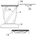
- FIG. 5A is a side elevational view of another inventive cup
- FIGS. 5B and 5C are perspective views of the cup as shown in FIG. 5A from above and from below;
- FIGS. 5D and 5E are bottom and top views of the FIG. 5A cup
- FIG. 6A is a sectional view through the cup of FIG. 4A when closed and collapsed.
- FIG. 6B is a perspective view from above of the collapsed cup of FIGS. 5A-E .
- a collapsible cup according to the invention has a cup body 10 , a reinforcement ring 20 , and a cap 30 .
- the body 10 has an upwardly flaring frustoconical side wall 11 centered on an axis A and terminating at an upper rim 12 that is bent over to form a downwardly open groove 15 .
- the wall 11 is closed downwardly at its lower end by a thick floor 13 from which projects a downwardly open annular flange 14 forming a radially inwardly open groove 16 and a downwardly open hole 17 of roughly the same inner diameter as an outer diameter of the body 10 at the floor 13 .
- the floor 13 is a disk having planar upper and lower faces extending perpendicular to the axis A.
- the side wall 11 is formed with a plurality, here four, of spiral or helical ridge formations 18 that are angularly equispaced about the axis A and that each extend from the floor 13 up to slightly below the upper rim 12 .
- the side wall 11 including the formations 18 , is of uniform wall thickness so that each formation 18 forms a respective inwardly open spiral groove 19 .
- the entire body 10 is formed of molded food-grade silicone and is sufficiently rigid to stand on its own, but still highly elastically deformable as will be described below.
- the ring 20 also shown in FIGS. 3A-3B is of plain construction of metal, preferable aluminum, stainless steel or the like and is quite rigid and only limitedly radially elastically deformable. It is of rectangular section and is normally fitted into the groove 15 formed by the bent-over rim 12 , where it is permanently fixed. It serves to reinforce the upper end of the body and hold it in a desired circular shape that cannot be radially expanded.
- the cap 30 also shown in FIGS. 2A-2E comprises a flat disk 31 from which downwardly extends a short tubularly cylindrical flange 32 of an outside diameter that is slightly less than an inside diameter of the upper end of the body 10 at the upper rim 12 .
- a planar and annular lip 33 projects radially outward from a cylindrical outer surface of the flange 32 .
- This cap 30 is also molded of one piece from a food-grade silicone that may be of somewhat greater rigidity than the body 10 . Thus this cap 30 can fit into the upper end of the body 10 with some radial compression of the seal lip 33 to effectively close the upper end of the cup body 10 .
- the cup body 10 When erect as shown in FIGS. 1A, 1D, 1E, and 1F the cup body 10 can contain a drinkable liquid. When the lid is fitted in place, the liquid is tightly contained.
- the entire cup can be axial compressed by pushing its upper and lower end faced toward each other in line with the axis A. Due to the presence of the spiral formations 18 , this axial compression will cause the upper end to rotate oppositely about the axis A relative to the lower end and ensure that the side wall 11 compacts uniformly until the outwardly projecting spiral formations 18 lie or nearly lie axially one atop the other. In fact this axial compaction can be aided by simultaneously oppositely twisting the upper and lower rims 12 and 14 , and in fact such axial opposite twisting will cause the cup body 11 to axially shorten.
- the flexible lower rim 14 can be inverted to deform up around the upper rim 12 reinforced by the ring 20 and flip over atop it, forming the entire cup into a compact and dimensionally stable coin-shaped body as shown in FIGS. 4A-4E .
- the cap 30 is normally upwardly closing the body 10 while this is done, but in fact the cup can be axially twist-compacted without the cap 30 in place.
- the entire cup with or without its cap can be pocketed or stored in a backpack or the like, taking up very little room. Yet when a cup is needed, the compacted cup can be restored to its erect condition simply by peeling back or de-inverting the inverted lower rim 14 , whereupon it will naturally spring elastically back into the full erect position shown in FIGS. 1A and 1D-1F .
- FIGS. 5A-F show an alternate model of the cup where instead of a separate cap 30 as described immediately above, there is a simple circular cap 30 ′ that fits tightly within the rim 12 and that is permanently secured to the cup body 11 at the rim 12 by a flexible tongue 34 formed unitarily of molded silicone with the rest of the cup.
- This cap 30 ′ also has a drink fitting 35 that can be snapped between an open and closed position to allow the liquid to be drunk from the cup without opening it, somewhat in the manner of an infant's sippy cup.
- This cup can also be compacted as shown in FIGS. 6A and 6B for packing and transport.
Landscapes
- Engineering & Computer Science (AREA)
- Mechanical Engineering (AREA)
- Table Devices Or Equipment (AREA)
Abstract
Description
Claims (8)
Priority Applications (1)
| Application Number | Priority Date | Filing Date | Title |
|---|---|---|---|
| US16/901,096 US11490713B2 (en) | 2020-05-22 | 2020-06-15 | Collapsible drinking cup |
Applications Claiming Priority (2)
| Application Number | Priority Date | Filing Date | Title |
|---|---|---|---|
| US202063029204P | 2020-05-22 | 2020-05-22 | |
| US16/901,096 US11490713B2 (en) | 2020-05-22 | 2020-06-15 | Collapsible drinking cup |
Publications (2)
| Publication Number | Publication Date |
|---|---|
| US20210361053A1 US20210361053A1 (en) | 2021-11-25 |
| US11490713B2 true US11490713B2 (en) | 2022-11-08 |
Family
ID=78609208
Family Applications (1)
| Application Number | Title | Priority Date | Filing Date |
|---|---|---|---|
| US16/901,096 Active 2041-02-12 US11490713B2 (en) | 2020-05-22 | 2020-06-15 | Collapsible drinking cup |
Country Status (1)
| Country | Link |
|---|---|
| US (1) | US11490713B2 (en) |
Families Citing this family (7)
| Publication number | Priority date | Publication date | Assignee | Title |
|---|---|---|---|---|
| WO2021138669A1 (en) | 2020-01-03 | 2021-07-08 | Miir Holdings, Llc | Methods for making a container, and related systems |
| US11490713B2 (en) * | 2020-05-22 | 2022-11-08 | Theo Andreas Stewart-Stand | Collapsible drinking cup |
| USD946352S1 (en) * | 2020-07-02 | 2022-03-22 | Miir Holdings, Llc | Cup with lid |
| USD945829S1 (en) * | 2021-04-14 | 2022-03-15 | Wenyong YUE | Water bottle |
| USD1009544S1 (en) | 2021-08-04 | 2024-01-02 | Miir Holdings, Llc | French press |
| USD1084774S1 (en) | 2023-03-01 | 2025-07-22 | Miir Holdings, Llc | Cup |
| USD1096318S1 (en) | 2023-11-29 | 2025-10-07 | Miir Holdings, Llc | Cup |
Citations (35)
| Publication number | Priority date | Publication date | Assignee | Title |
|---|---|---|---|---|
| US248867A (en) * | 1881-11-01 | Drinking cup or glass | ||
| US296902A (en) * | 1884-04-15 | Collapsing cup | ||
| US577764A (en) * | 1897-02-23 | John lines | ||
| US761559A (en) * | 1903-05-21 | 1904-05-31 | Edythe Totten | Portable tea-steeper. |
| US1048935A (en) * | 1912-09-25 | 1912-12-31 | John F Brady | Drinking-cup. |
| US1093873A (en) * | 1913-04-14 | 1914-04-21 | John F Mitchell | Collapsible drinking-cup. |
| US1228706A (en) * | 1915-12-02 | 1917-06-05 | William F Smythe | Collapsible drinking-cup. |
| US1233117A (en) * | 1917-03-28 | 1917-07-10 | Henry M Parker | Collapsible fabric bucket. |
| US1264040A (en) * | 1917-04-03 | 1918-04-23 | Wallace D Fackler | Drinking-cup. |
| US1464548A (en) * | 1922-01-27 | 1923-08-14 | George R Stephens | Collapsible bucket |
| US1581418A (en) * | 1924-08-04 | 1926-04-20 | Walter S Baker | Drinking cup |
| US2886084A (en) * | 1958-07-30 | 1959-05-12 | Delphine L Davison | Collapsible double wall container |
| US3946903A (en) * | 1971-07-30 | 1976-03-30 | Carol Parker | Collapsible, spirally fluted container |
| US4408644A (en) * | 1981-12-08 | 1983-10-11 | Svantesson & Andersson Mekaniska (Samek) Ab | Drinking cup |
| US4872576A (en) * | 1987-07-17 | 1989-10-10 | Tadashi Nakamura | Soft-metal made can body with squashing guides |
| US4930644A (en) * | 1988-12-22 | 1990-06-05 | Robbins Edward S Iii | Thin film container with removable lid and related process |
| US20030160055A1 (en) * | 2002-02-01 | 2003-08-28 | Cockroach Design Llc | Collapsible drinking and storage receptacle |
| US20130032592A1 (en) * | 2011-02-11 | 2013-02-07 | Nova Lee | Leak proof collapsible cup |
| US20130075393A1 (en) * | 2011-08-16 | 2013-03-28 | David B. Haynie | Collapsible bottle |
| US8684230B1 (en) * | 2011-06-14 | 2014-04-01 | Russell Jon Greenberg | Twistable and collapsible container for dispensing measured dosages of liquid |
| US20140332528A1 (en) * | 2013-05-13 | 2014-11-13 | Jason A. Blum | Collapsible cup for hot and cold beverages |
| US20150253055A1 (en) * | 2014-03-10 | 2015-09-10 | Sam Tung Tsui | Collapsible Multi-Purpose Containers |
| US20150313389A1 (en) * | 2014-04-30 | 2015-11-05 | Vera Isidro Velasquez | Collapsible Bottle Apparatus |
| US20160309930A1 (en) * | 2015-04-24 | 2016-10-27 | Gregory Stewart | Expandable drinking cup assembly with lid and straw |
| US20170253363A1 (en) * | 2016-03-04 | 2017-09-07 | Silikids, Inc. | Silicone Cup with Metal Ring and Openings for Inserting Metal Ring |
| US20180194517A1 (en) * | 2015-07-03 | 2018-07-12 | Pocket Enterprises Limited | Reusable Cup |
| US20200062469A1 (en) * | 2018-03-28 | 2020-02-27 | Gameel Gabriel | Volume-reducing overlapping-scale container system and method |
| US10694835B2 (en) * | 2018-03-15 | 2020-06-30 | Otter Products, Llc | Protective case for use with device grip |
| US20200231324A1 (en) * | 2019-01-17 | 2020-07-23 | Stojo Products Inc. | Collapsible Travel Bottle |
| US20200305619A1 (en) * | 2019-04-01 | 2020-10-01 | Sam Tung Tsui | Collapsible cup |
| US20210237933A1 (en) * | 2020-02-04 | 2021-08-05 | Stojo Products Inc. | Collapsible Food Container |
| US20210361053A1 (en) * | 2020-05-22 | 2021-11-25 | Theo Andreas Stewart-Stand | Collapsible drinking cup |
| USD940506S1 (en) * | 2020-06-25 | 2022-01-11 | Hydaway, LLC | Collapsible tumbler |
| US11284525B2 (en) * | 2019-06-21 | 2022-03-22 | St. Croix Product Labs | Storage accessory for mobile electronic device |
| US20220227530A1 (en) * | 2021-01-15 | 2022-07-21 | Saba Kuli KHAN | Collapsible containers |
-
2020
- 2020-06-15 US US16/901,096 patent/US11490713B2/en active Active
Patent Citations (35)
| Publication number | Priority date | Publication date | Assignee | Title |
|---|---|---|---|---|
| US248867A (en) * | 1881-11-01 | Drinking cup or glass | ||
| US296902A (en) * | 1884-04-15 | Collapsing cup | ||
| US577764A (en) * | 1897-02-23 | John lines | ||
| US761559A (en) * | 1903-05-21 | 1904-05-31 | Edythe Totten | Portable tea-steeper. |
| US1048935A (en) * | 1912-09-25 | 1912-12-31 | John F Brady | Drinking-cup. |
| US1093873A (en) * | 1913-04-14 | 1914-04-21 | John F Mitchell | Collapsible drinking-cup. |
| US1228706A (en) * | 1915-12-02 | 1917-06-05 | William F Smythe | Collapsible drinking-cup. |
| US1233117A (en) * | 1917-03-28 | 1917-07-10 | Henry M Parker | Collapsible fabric bucket. |
| US1264040A (en) * | 1917-04-03 | 1918-04-23 | Wallace D Fackler | Drinking-cup. |
| US1464548A (en) * | 1922-01-27 | 1923-08-14 | George R Stephens | Collapsible bucket |
| US1581418A (en) * | 1924-08-04 | 1926-04-20 | Walter S Baker | Drinking cup |
| US2886084A (en) * | 1958-07-30 | 1959-05-12 | Delphine L Davison | Collapsible double wall container |
| US3946903A (en) * | 1971-07-30 | 1976-03-30 | Carol Parker | Collapsible, spirally fluted container |
| US4408644A (en) * | 1981-12-08 | 1983-10-11 | Svantesson & Andersson Mekaniska (Samek) Ab | Drinking cup |
| US4872576A (en) * | 1987-07-17 | 1989-10-10 | Tadashi Nakamura | Soft-metal made can body with squashing guides |
| US4930644A (en) * | 1988-12-22 | 1990-06-05 | Robbins Edward S Iii | Thin film container with removable lid and related process |
| US20030160055A1 (en) * | 2002-02-01 | 2003-08-28 | Cockroach Design Llc | Collapsible drinking and storage receptacle |
| US20130032592A1 (en) * | 2011-02-11 | 2013-02-07 | Nova Lee | Leak proof collapsible cup |
| US8684230B1 (en) * | 2011-06-14 | 2014-04-01 | Russell Jon Greenberg | Twistable and collapsible container for dispensing measured dosages of liquid |
| US20130075393A1 (en) * | 2011-08-16 | 2013-03-28 | David B. Haynie | Collapsible bottle |
| US20140332528A1 (en) * | 2013-05-13 | 2014-11-13 | Jason A. Blum | Collapsible cup for hot and cold beverages |
| US20150253055A1 (en) * | 2014-03-10 | 2015-09-10 | Sam Tung Tsui | Collapsible Multi-Purpose Containers |
| US20150313389A1 (en) * | 2014-04-30 | 2015-11-05 | Vera Isidro Velasquez | Collapsible Bottle Apparatus |
| US20160309930A1 (en) * | 2015-04-24 | 2016-10-27 | Gregory Stewart | Expandable drinking cup assembly with lid and straw |
| US20180194517A1 (en) * | 2015-07-03 | 2018-07-12 | Pocket Enterprises Limited | Reusable Cup |
| US20170253363A1 (en) * | 2016-03-04 | 2017-09-07 | Silikids, Inc. | Silicone Cup with Metal Ring and Openings for Inserting Metal Ring |
| US10694835B2 (en) * | 2018-03-15 | 2020-06-30 | Otter Products, Llc | Protective case for use with device grip |
| US20200062469A1 (en) * | 2018-03-28 | 2020-02-27 | Gameel Gabriel | Volume-reducing overlapping-scale container system and method |
| US20200231324A1 (en) * | 2019-01-17 | 2020-07-23 | Stojo Products Inc. | Collapsible Travel Bottle |
| US20200305619A1 (en) * | 2019-04-01 | 2020-10-01 | Sam Tung Tsui | Collapsible cup |
| US11284525B2 (en) * | 2019-06-21 | 2022-03-22 | St. Croix Product Labs | Storage accessory for mobile electronic device |
| US20210237933A1 (en) * | 2020-02-04 | 2021-08-05 | Stojo Products Inc. | Collapsible Food Container |
| US20210361053A1 (en) * | 2020-05-22 | 2021-11-25 | Theo Andreas Stewart-Stand | Collapsible drinking cup |
| USD940506S1 (en) * | 2020-06-25 | 2022-01-11 | Hydaway, LLC | Collapsible tumbler |
| US20220227530A1 (en) * | 2021-01-15 | 2022-07-21 | Saba Kuli KHAN | Collapsible containers |
Also Published As
| Publication number | Publication date |
|---|---|
| US20210361053A1 (en) | 2021-11-25 |
Similar Documents
| Publication | Publication Date | Title |
|---|---|---|
| US11490713B2 (en) | Collapsible drinking cup | |
| US10214336B2 (en) | Combined wine glass and wine bottle package | |
| US6736285B2 (en) | Collapsible drinking and storage receptacle | |
| US6883677B2 (en) | Disposable drinking device | |
| CA2510072C (en) | Plastic container | |
| US20090266737A1 (en) | Beverage container permitting multiple configurations | |
| US20060016819A1 (en) | Bottle assembly with removable container assembly | |
| US7757885B2 (en) | Disposable container with deformable brim | |
| US20120168451A1 (en) | Drinking cup that rotatably attaches to a plastic bottle for closure and protection | |
| AU2005297839A1 (en) | Bottle cap | |
| US2786495A (en) | Beverage flask for filling drinking glasses | |
| US10919679B1 (en) | Multiple compartment container assembly | |
| EP3289930B1 (en) | A combination glass and bottle package | |
| US12383047B1 (en) | Insulated bottle for liquids with secondary storage compartment | |
| RU43537U1 (en) | BOTTLE FOR BEVERAGES PREVIOUSLY CARBONATED | |
| CN215502365U (en) | Staggered cup convenient to stack | |
| CN201376750Y (en) | Beverage receptacle | |
| JPH018531Y2 (en) | ||
| KR200325536Y1 (en) | A double bottle | |
| JPS5931530Y2 (en) | An aluminum container that is molded in one piece and is suitable for removal using a stand. | |
| KR20250087368A (en) | Tea extractor | |
| KR200429845Y1 (en) | Portable Cup Storage Container with Bottle Opener | |
| USRE18215E (en) | Liquid container | |
| JP2024122433A (en) | Beverage containers | |
| WO2006021143A1 (en) | A portable multi-functional beverage container |
Legal Events
| Date | Code | Title | Description |
|---|---|---|---|
| FEPP | Fee payment procedure |
Free format text: ENTITY STATUS SET TO UNDISCOUNTED (ORIGINAL EVENT CODE: BIG.); ENTITY STATUS OF PATENT OWNER: MICROENTITY |
|
| FEPP | Fee payment procedure |
Free format text: ENTITY STATUS SET TO MICRO (ORIGINAL EVENT CODE: MICR); ENTITY STATUS OF PATENT OWNER: MICROENTITY |
|
| STPP | Information on status: patent application and granting procedure in general |
Free format text: DOCKETED NEW CASE - READY FOR EXAMINATION |
|
| STPP | Information on status: patent application and granting procedure in general |
Free format text: NON FINAL ACTION MAILED |
|
| STPP | Information on status: patent application and granting procedure in general |
Free format text: NOTICE OF ALLOWANCE MAILED -- APPLICATION RECEIVED IN OFFICE OF PUBLICATIONS |
|
| STPP | Information on status: patent application and granting procedure in general |
Free format text: PUBLICATIONS -- ISSUE FEE PAYMENT VERIFIED |
|
| STCF | Information on status: patent grant |
Free format text: PATENTED CASE |