US11489394B2 - Slot wedge element, stator device, motor, and wind turbine - Google Patents
Slot wedge element, stator device, motor, and wind turbine Download PDFInfo
- Publication number
- US11489394B2 US11489394B2 US16/766,574 US201916766574A US11489394B2 US 11489394 B2 US11489394 B2 US 11489394B2 US 201916766574 A US201916766574 A US 201916766574A US 11489394 B2 US11489394 B2 US 11489394B2
- Authority
- US
- United States
- Prior art keywords
- slot wedge
- wedge element
- thickness
- edge
- stator device
- Prior art date
- Legal status (The legal status is an assumption and is not a legal conclusion. Google has not performed a legal analysis and makes no representation as to the accuracy of the status listed.)
- Active, expires
Links
- 238000004804 winding Methods 0.000 claims abstract description 16
- 239000002826 coolant Substances 0.000 claims description 48
- 230000003068 static effect Effects 0.000 claims description 34
- 230000007423 decrease Effects 0.000 claims description 23
- 230000002093 peripheral effect Effects 0.000 claims description 6
- 230000008859 change Effects 0.000 claims description 5
- 230000000284 resting effect Effects 0.000 claims 3
- 238000010586 diagram Methods 0.000 description 15
- 238000001816 cooling Methods 0.000 description 13
- 230000000694 effects Effects 0.000 description 6
- 238000000034 method Methods 0.000 description 5
- 230000003247 decreasing effect Effects 0.000 description 3
- 230000008569 process Effects 0.000 description 3
- 238000009423 ventilation Methods 0.000 description 3
- XEEYBQQBJWHFJM-UHFFFAOYSA-N Iron Chemical compound [Fe] XEEYBQQBJWHFJM-UHFFFAOYSA-N 0.000 description 2
- 230000009286 beneficial effect Effects 0.000 description 2
- 238000013021 overheating Methods 0.000 description 2
- 239000007787 solid Substances 0.000 description 2
- RYGMFSIKBFXOCR-UHFFFAOYSA-N Copper Chemical compound [Cu] RYGMFSIKBFXOCR-UHFFFAOYSA-N 0.000 description 1
- 239000004020 conductor Substances 0.000 description 1
- 229910052802 copper Inorganic materials 0.000 description 1
- 239000010949 copper Substances 0.000 description 1
- 230000001419 dependent effect Effects 0.000 description 1
- 230000017525 heat dissipation Effects 0.000 description 1
- 238000000265 homogenisation Methods 0.000 description 1
- 229910052742 iron Inorganic materials 0.000 description 1
- 230000000116 mitigating effect Effects 0.000 description 1
- 238000012986 modification Methods 0.000 description 1
- 230000004048 modification Effects 0.000 description 1
- 230000009467 reduction Effects 0.000 description 1
- 230000035882 stress Effects 0.000 description 1
- 230000001360 synchronised effect Effects 0.000 description 1
- 230000008646 thermal stress Effects 0.000 description 1
Images


Classifications
-
- H—ELECTRICITY
- H02—GENERATION; CONVERSION OR DISTRIBUTION OF ELECTRIC POWER
- H02K—DYNAMO-ELECTRIC MACHINES
- H02K3/00—Details of windings
- H02K3/46—Fastening of windings on the stator or rotor structure
- H02K3/48—Fastening of windings on the stator or rotor structure in slots
- H02K3/487—Slot-closing devices
-
- F—MECHANICAL ENGINEERING; LIGHTING; HEATING; WEAPONS; BLASTING
- F03—MACHINES OR ENGINES FOR LIQUIDS; WIND, SPRING, OR WEIGHT MOTORS; PRODUCING MECHANICAL POWER OR A REACTIVE PROPULSIVE THRUST, NOT OTHERWISE PROVIDED FOR
- F03D—WIND MOTORS
- F03D80/00—Details, components or accessories not provided for in groups F03D1/00 - F03D17/00
- F03D80/60—Cooling or heating of wind motors
-
- F—MECHANICAL ENGINEERING; LIGHTING; HEATING; WEAPONS; BLASTING
- F03—MACHINES OR ENGINES FOR LIQUIDS; WIND, SPRING, OR WEIGHT MOTORS; PRODUCING MECHANICAL POWER OR A REACTIVE PROPULSIVE THRUST, NOT OTHERWISE PROVIDED FOR
- F03D—WIND MOTORS
- F03D9/00—Adaptations of wind motors for special use; Combinations of wind motors with apparatus driven thereby; Wind motors specially adapted for installation in particular locations
- F03D9/20—Wind motors characterised by the driven apparatus
- F03D9/25—Wind motors characterised by the driven apparatus the apparatus being an electrical generator
-
- H—ELECTRICITY
- H02—GENERATION; CONVERSION OR DISTRIBUTION OF ELECTRIC POWER
- H02K—DYNAMO-ELECTRIC MACHINES
- H02K3/00—Details of windings
- H02K3/04—Windings characterised by the conductor shape, form or construction, e.g. with bar conductors
- H02K3/24—Windings characterised by the conductor shape, form or construction, e.g. with bar conductors with channels or ducts for cooling medium between the conductors
-
- H—ELECTRICITY
- H02—GENERATION; CONVERSION OR DISTRIBUTION OF ELECTRIC POWER
- H02K—DYNAMO-ELECTRIC MACHINES
- H02K7/00—Arrangements for handling mechanical energy structurally associated with dynamo-electric machines, e.g. structural association with mechanical driving motors or auxiliary dynamo-electric machines
- H02K7/18—Structural association of electric generators with mechanical driving motors, e.g. with turbines
- H02K7/1807—Rotary generators
- H02K7/1823—Rotary generators structurally associated with turbines or similar engines
- H02K7/183—Rotary generators structurally associated with turbines or similar engines wherein the turbine is a wind turbine
-
- F—MECHANICAL ENGINEERING; LIGHTING; HEATING; WEAPONS; BLASTING
- F05—INDEXING SCHEMES RELATING TO ENGINES OR PUMPS IN VARIOUS SUBCLASSES OF CLASSES F01-F04
- F05B—INDEXING SCHEME RELATING TO WIND, SPRING, WEIGHT, INERTIA OR LIKE MOTORS, TO MACHINES OR ENGINES FOR LIQUIDS COVERED BY SUBCLASSES F03B, F03D AND F03G
- F05B2260/00—Function
- F05B2260/20—Heat transfer, e.g. cooling
-
- H—ELECTRICITY
- H02—GENERATION; CONVERSION OR DISTRIBUTION OF ELECTRIC POWER
- H02K—DYNAMO-ELECTRIC MACHINES
- H02K1/00—Details of the magnetic circuit
- H02K1/06—Details of the magnetic circuit characterised by the shape, form or construction
- H02K1/12—Stationary parts of the magnetic circuit
- H02K1/20—Stationary parts of the magnetic circuit with channels or ducts for flow of cooling medium
-
- Y—GENERAL TAGGING OF NEW TECHNOLOGICAL DEVELOPMENTS; GENERAL TAGGING OF CROSS-SECTIONAL TECHNOLOGIES SPANNING OVER SEVERAL SECTIONS OF THE IPC; TECHNICAL SUBJECTS COVERED BY FORMER USPC CROSS-REFERENCE ART COLLECTIONS [XRACs] AND DIGESTS
- Y02—TECHNOLOGIES OR APPLICATIONS FOR MITIGATION OR ADAPTATION AGAINST CLIMATE CHANGE
- Y02E—REDUCTION OF GREENHOUSE GAS [GHG] EMISSIONS, RELATED TO ENERGY GENERATION, TRANSMISSION OR DISTRIBUTION
- Y02E10/00—Energy generation through renewable energy sources
- Y02E10/70—Wind energy
- Y02E10/72—Wind turbines with rotation axis in wind direction
Definitions
- the present disclosure relates to a technical field of motors, and particularly relates to a slot wedge element, a stator device, a motor and a wind turbine.
- One object of the present disclosure is to provide a slot wedge element, a stator device, a motor and a wind turbine, which can make a distribution of a cooling air in radial channels of the stator device to be more uniform in an axial direction, so as to improve a cooling effect on the motor.
- the embodiments of the present disclosure provides a slot wedge element for a stator device, wherein the slot wedge element extends in a first direction and includes a first edge and a second edge opposite to each other, and the slot wedge element includes a first surface and a second surface in its thickness direction, and is attached to a winding of the stator device via the first surface; the second surface includes a first portion, a second portion and a third portion which are sequentially and continuously distributed in the first direction, wherein the first portion is connected with the first edge, and the third portion is connected with the second edge; and wherein, a second thickness between the second portion and the first surface is greater than a first thickness between the first portion and the first surface, the second thickness is greater than or equal to a third thickness between the third portion and the first surface, and the first thickness decreases progressively in a direction from the second portion to the first edge.
- a stator device includes: a core, including at least four core members spaced apart in an axial direction of the stator device, each of which is provided with a plurality of slots spaced apart in a circumferential direction, and the plurality of slots of the at least four core members are arranged to correspond one by one in the axial direction; a plurality of windings, each of which is arranged in the slots in the axial direction; and a plurality of slot wedge elements according to any of the above-mentioned embodiments, each of which is arranged in the slots in the axial direction and attached to the winding via the first surface.
- the embodiments of the present disclosure provide a motor, which includes a stator device as described above, wherein the stator device is fixed by a stator bracket, and each adjacent wo core members in the stator device define a radial channel; and a rotor device, disposed surrounding the stator device on a peripheral side of the stator device, or the stator device is disposed surrounding the rotor device on a peripheral side of the rotor device, the motor includes chambers on two ends in the axial direction, an air gap is formed between the rotor device and the slot wedge element, and the chambers, the air gap and the radial channels are communicated to define a channel for flow of a cooling medium.
- the embodiments of the present disclosure provide a wind turbine, including a motor as described above.
- the slot wedge element in the stator device can reduce the local resistance on the flow of the cooling medium at inlets of the air gap in the motor, and make the cooling medium in the radial channels of the stator device to distribute more evenly in the axial direction, thereby improving the cooling effect on the motor and improving the power density of the motor.
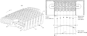
- FIG. 1 is a flow distribution schematic diagram of a cooling medium in a motor in the prior art.
- FIG. 2 is a static pressure distribution schematic diagram of a cooling medium in a motor in the prior art.
- FIG. 3 is a local structural schematic diagram of a motor sectioned in an axial direction provided in the embodiments of the present disclosure.
- FIG. 4 is a structural schematic diagram of a stator device provided in the embodiments of the present disclosure.
- FIG. 5 is a structural schematic diagram of a slot wedge element of a first type provided in the embodiments of the present disclosure
- FIG. 6 is a flow distribution schematic diagram of a cooling medium in a motor provided in the embodiments of the present disclosure.
- FIG. 7 is a static pressure distribution schematic diagram of a cooling medium in a motor provided in the embodiments of the present disclosure.
- FIG. 8 is a structural schematic diagram of a slot wedge element of a second type provided in the embodiments of the present disclosure.
- FIG. 9 is a structural schematic diagram of a slot wedge element of a third type provided in the embodiments of the present disclosure.
- FIG. 10 is a structural schematic diagram of a slot wedge element of a fourth type provided in the embodiments of the present disclosure.
- FIG. 11 is a structural schematic diagram of a slot wedge element of a fifth type provided in the embodiments of the present disclosure.
- FIG. 12 is a structural schematic diagram of a slot wedge element of a sixth type provided in the embodiments of the present disclosure.
- FIG. 13 is a structural schematic diagram of a slot wedge element of a seventh type provided in the embodiments of the present disclosure.
- FIG. 1 - FIG. 13 a slot wedge element, a stator device, a motor and a wind turbine according to the embodiments of the present disclosure will be described in detail by reference to FIG. 1 - FIG. 13 .
- the radial ventilation cooling mode is realized by communicating an air gap A formed between a stator 1 and a rotor 2 , a plurality of radial channels W in the stator 1 and chambers 3 at both ends of the motor in an axial direction thereof. After a cooling medium flows into the air gap A from the chambers 3 at both ends, it is divided by the plurality of radial channels W and flows out of the stator 1 , thereby completing the cooling of the motor.
- the flow of the cooling medium in the air gap A presents a trend of decreasing gradually from two end sides in the axial direction to a middle confluence point due to the dividing of the cooling medium by the radial channels W in the stator 1 .
- a flow velocity of the cooling medium in the air gap A presents a trend of decreasing gradually from the two end sides in the axial direction to the middle confluence point, since generally a cross-sectional area of an axial flow in the air gap A remains constant and axial thicknesses of the radial channels W are the same.
- the static pressure distribution of the cooling medium in the air gap A presents a trend of increasing gradually from the two end sides to the middle confluence point.
- inlets of the multiple radial channels W distributed in the axial direction are all located in the air gap A, wherein P 1 is a static pressure of a first radial channel on one side in the axial direction, P 2 is a static pressure of a second radial channel, P 6 is a static pressure of a sixth radial channel on the other side in the axial direction, P 5 is a static pressure of a fifth radial channel, and P 3 and P 4 are a static pressure of a third radial channel and a static pressure of a fourth radial channel at the middle confluence point, respectively.
- the static pressure difference in the radial channel W is formed by resistance dissipation in the flowing of the cooling medium in the radial channel W, that is to say, the flow velocity of the cooling medium in the radial channel W with a higher static pressure difference, which is located at the middle in the axial direction, is larger, while the flow velocity of the cooling medium in the radial channel W, the static pressure difference of which is lower as being closer to the two end sides in the axial direction, is smaller. Due to the consistent structure of the radial channels W distributed in the axial direction, a flow of the cooling medium in the radial channel W with a larger flow velocity is larger, while the flow of the cooling medium in the radial channel W with a smaller flow velocity is smaller.
- the flows of the cooling medium in the radial channels W present a trend of decreasing gradually from the middle to the two end sides in the axial direction, as shown by the flows of the respective radial channels indicated by the hollow dots in the FIG. 1 .
- the stator 1 Since the loss of the stator 1 is distributed relatively uniformly, the stator cannot be uniformly cooled in the axial direction due to the nonuniform flow distribution of the cooling medium in the multiple radial channels W in the axial direction, resulting in a large difference of the temperature in the stator in the axial direction. Finally, as shown by a stator temperature distribution curve in FIG. 1 , the temperature distribution of the stator, in which the loss distribution is uniform, is uneven in the axial direction, resulting in local overheating and large structural thermal stress of the stator 1 .
- the embodiments of the present disclosure provide a motor, which includes a stator device 100 and a rotor device 200 .
- the stator device 100 includes a core 20 , a plurality of windings 30 and a plurality of slot wedge elements 10 .
- the core 20 includes at least four core members 21 spaced apart in an axial direction X of the stator device 100 , each core member 21 is provided with a plurality of slots 22 spaced apart in a circumferential direction, and the plurality of slots 22 of the at least four core members 21 are arranged to correspond one by one in the axial direction X.
- Each winding 30 is arranged in the slots 22 in the axial direction X.
- a pad strip 23 extending in the axial direction X is disposed, and each winding 30 is disposed in a space defined by the slots 22 and the pad strip 23 in the axial direction X.
- Each slot wedge element 10 is disposed in the slots 22 in the axial direction X and is attached to the winding 30 via a first surface 11 .
- the slot wedge element 10 may be connected with portions on both sides of the slot 22 by means of joggle joints.
- the stator device 100 is fixed by a stator bracket (not shown in the figure), and a radial channel W is formed between each adjacent two core members 21 in the stator device 100 .
- the rotor device 200 is disposed surrounding the stator device 100 on a peripheral side of the stator device 100 , or the stator device 100 is disposed surrounding the rotor device 200 on a peripheral side of the rotor device 200 .
- Chambers C are disposed on both ends of the motor in the axial direction, and an air gap A is formed between the rotor device 200 and the slot wedge elements 10 , wherein the chambers C are communicated with the air gap A and the radial channels W to form a channel for flow of a cooling medium. Since there are more than three radial channels W, a flow process of the cooling medium in the radial channels W can be regarded as a flow process of the cooling medium in more than three parallel lines.
- a slot wedge element 10 may be constructed to change a cross-sectional area of the air gap A in the axial direction formed between the rotor device 200 and the slot wedge element 10 , so as to adjust flow and static pressure distribution of a cooling air d flowing in the air gap A, and finally homogenize an axial distribution of the flows of the cooling air in the radial channels W, which are communicated with the air gap A.
- the embodiments of the present disclosure provide a slot wedge element 10 , which can be applied to the stator device 100 as shown in FIG. 3 and FIG. 4 .
- the slot wedge element 10 extends in a first direction X and includes a first edge 13 and a second edge 14 opposite to each other.
- the slot wedge element 10 includes a first surface 11 and a second surface 12 in its thickness direction, and in the first direction X, the slot wedge element 10 is attached to the winding of the stator device via the first surface 11 .
- the second surface 12 includes a first portion 12 a , a second portion 12 b and a third portion 12 c sequentially and continuously distributed in the first direction X.
- the first portion 12 a is connected with the first edge 13
- the third portion 12 c is connected with the second edge 14 .
- Each of the first edge 13 and the second edge 14 may be a straight line or a plane surface with a certain thickness.
- a second thickness between the second portion 12 b and the first surface 11 is greater than a first thickness between the first portion 12 a and the first surface 11 , the second thickness is greater than or equal to a third thickness between the third portion 12 c and the first surface 11 , and the first thickness decreases progressively in a direction from the second portion 12 b to the first edge 13 .
- the third thickness decreases progressively in a direction from the second portion 12 b to the second edge 14 .
- a cross-sectional area of the flow in the axial direction X in the air gap A formed between the rotor device 200 and the slot wedge element 10 presents a change trend of gradually shrinking in the direction from the first edge 13 or the second edge 14 to the second portion 12 b .
- the change trend of the gradually shrinking is symmetrical from two axial end sides to a middle confluence point, as shown in FIG. 5 .
- the cross-sectional area of the flow in the axial direction X in the air gap A formed between the rotor device 200 and the slot wedge element 10 is equal on a side from the second portion 12 b to the second edge 14 , while decreases progressively in the direction from the second portion 12 b to the first edge 13 .
- FIG. 6 and FIG. 7 respectively show a flow distribution diagram and a static pressure distribution diagram of the cooling medium in a motor according to the embodiments of the present disclosure adopting the slot wedge element 10 as shown in FIG. 5 .
- the cross-sectional area of the flow in the axial direction X in the air gap A formed between the rotor device 200 and the slot wedge element 10 decreases gradually, thereby mitigating the gradient of the flow velocity of the cooling medium in the air gap A from the two axial end sides to the middle confluence point.
- the gradient of the static pressure which is opposite to the gradient of the flow velocity in direction, is also mitigated.
- the static pressure distribution in the axial direction X in the air gap A is more uniform, as shown in the static pressure distribution curve of the air gap A in FIG. 7 .
- the homogenization of the static pressure level in the air gap A makes the static pressure levels at the respective inlets of radial channels W in the axial direction and the static pressure differences in the respective radial channels W to be closer to each other, as shown by the static pressure differences of the respective radial channels represented by the solid dots in FIG. 7 , and finally making the flows of the cooling medium in the respective radial channels W distributed in the axial direction to be more uniform, as shown by the flows of the respective radial channels indicated by the hollow dots in FIG. 6 .
- the stator device 100 with relatively uniform loss distribution may be cooled more evenly in the axial direction, as shown in the temperature distribution curve of the stator device in FIG. 6 .
- the temperature difference of the stator device 100 in the axial direction X is relatively small, and thus the temperature distribution of the stator device 100 in the axial direction is relatively uniform, thereby eliminating the local overheating and excessive structural then al stress that may occur in the operation of the motor.
- the cross-sectional area of the flow in the axial direction X in the air gap A formed between the rotor device 200 and the slot wedge element 10 gradually decreases at least from one of the first edge 13 and the second edge 14 to the second portion 12 b , thereby affecting the flow and static pressure distribution of the cooling medium flowing in the air gap A and the radial channels W in a coordinated manner, which can reduce a local resistance to the flowing of the cooling medium at inlets of the air gap A, and make the flow distribution of the cooling medium in the radial channels W of the stator device 100 to be more uniform in the axial direction X, and thus improve the cooling effect on the generator.
- the first surface 11 of the slot wedge element 10 is a plane surface
- the second portion 12 b is a dividing line formed between the first portion 12 a and the third portion 12 c .
- the dividing line may be a straight line, a broken line, a curved line, or the like. The embodiments of the present disclosure are described by taking the dividing line of a straight line as an example.
- the first thickness decreases progressively in a gradient type in the direction from the second portion 12 b to the first edge 13
- the third thickness decreases progressively in a gradient type in the direction from the second portion 12 b to the second edge 14 .
- the first portion 12 a and the third portion 12 c are each formed as an inclined surface, to adjust the cross-sectional area of the flow in the axial direction X in the air gap A, as shown in FIG. 5 .
- the first portion 12 a and the third portion 12 c are each formed as two or more inclined surfaces which are continuously distributed, as shown in FIG. 8 , which may mitigate the gradient of the cross-sectional area of the flow in the axial direction X in the air gap A, compared with the configuration of merely one inclined surface as shown in FIG. 5 .
- the first portion 12 a and the third portion 12 c are each formed as one concave surface, as shown in FIG. 10 , which may increase the gradient of the cross-sectional area of the flow in the axial direction X in the air gap A, compared with the configuration of the inclined surface as shown in FIG. 5 .
- the first portion 12 a and the third portion 12 c are each formed as one convex surface, as shown in FIG. 10 , which may mitigate the gradient of the cross-sectional area of the flow in the axial direction X in the air gap A, compared with the configuration of the inclined surface as shown in FIG. 5 .
- first portion 12 a and the third portion 12 c may be arranged symmetrically with respect to the second portion 12 b , as shown in FIG. 5 , and FIG. 8 to FIG. 10 . Further, the first portion 12 a and the third portion 12 c may be arranged asymmetrically with respect to the second portion 12 b , for example, but not limited to, the first portion 12 a is formed as one inclined surface or two or more inclined surfaces which are continuously distributed while the third portion 12 c is formed as the convex surface or the concave surface, and other combination manners are also available; or, the first portion 12 a and the third portion 12 c have the same shape, but have different length dimensions in the axial direction X; or, the third portion 12 c is formed as a plane surface parallel to the first surface 11 so that the third thickness of the slot wedge element 10 is equal to the second thickness, while the first thickness decreases progressively in the gradient type in the direction from the second portion 12 b to the first edge 13 .
- the slot wedge element 10 is configured such that the first portion 12 a and the third portion 12 c are arranged symmetrically with respect to the second portion 12 b .
- the slot wedge element 10 is configured such that the first portion 12 a and the third portion 12 c are arranged asymmetrically with respect to the second portion 12 b , and that the second portion 12 b is closer to the side of the air gap A with a smaller flow of the cooling medium.
- the stator device 100 adopts the slot wedge element 10 as shown in FIG. 5 or FIG. 8 , in which the second portion 12 b is formed as the dividing line, the flows of the cooling medium in the respective radial channels W still present a trend of being larger at the middle confluence point while being smaller on the two sides in the axial direction X, it is preferable to use the slot wedge element 10 with the convex surface as shown in FIG. 10 ; if the flows of the cooling medium in the respective radial channels W present a trend of being smaller at the middle confluence point while being larger on the two sides in the axial direction X, the slot wedge element 10 with the concave surface as shown in FIG. 9 may be used.
- the embodiments of the present disclosure further provides a slot wedge element 10 , which has a similar configuration to the slot wedge element 10 as shown in FIG. 5 , except that the second portion 12 b is formed as a plane surface connecting the first portion 12 a and the third portion 12 c , and has a length dimension in the first direction X smaller than a length dimension in the first direction X of the first surface 11 .
- the length dimension in the first direction X of the second portion 12 b is smaller than the length dimensions in the first direction X of the first portion 12 a and of the third portion 12 c , so as to adjust the cross-sectional area of the flow in the axial direction X in the air gap A formed between the rotor device 200 and the slot wedge element 10 in a relatively wide range.
- the first portion 12 a and the third portion 12 c may be symmetrically equal or unequal with respect to the second portion 12 b.
- first portion 12 a and the third portion 12 c are each formed as one inclined surface, as shown in FIG. 11 .
- the first portion 12 a and the third portion 12 c each may be formed as any of the two or more inclined surfaces continuously distributed, one concave surface and one convex surface, and the first portion 12 a and the third portion 12 c may be arranged symmetrically with respect the second portion 12 b (similar to the configuration of the slot wedge element 10 as shown in FIG. 5 , FIG. 8 to FIG. 10 ), or may be arranged asymmetrically, specifically depending on whether the flows of the cooling medium at the inlets of the air gap A on the two end sides in the axial direction are equal, which will not be discussed in detail.
- the length in the axial direction X of the plane surface of the second portion 12 b may be lengthened, in addition to adopting the slot wedge element 10 which includes a second portion 12 b of a plane surface and a convex surface; If the flows of cooling medium in the respective radial channels W present a trend of being smaller at the middle confluence point and being larger on the two sides in the axial direction X, the length in the axial direction X of the plane surface of the second portion 12 b may be shortened, in addition to adopting the slot wedge element 10 which includes a second portion 12 b of a plane surface and a concave surface.
- the embodiments of the present disclosure further provide a slot wedge element 10 , a configuration of which is similar to the configuration of the slot wedge element 10 as shown in FIG. 5 or FIG. 11 , except that the first thickness decreases progressively in a step type in the direction from the second portion 12 b to the first edge 13 , the third thickness decreases progressively in a step manner in the direction from the second portion 12 b to the second edge 14 , and at least one of the first portion 12 a and the third portion 12 c includes one or more step surfaces, and preferably, height differences of respective adjacent two step surfaces are equal, so as to mitigate the gradient of the cross-sectional area of the flow in the axial direction X in the air gap A.
- the second portion 12 b may be a dividing line formed between the first portion 12 a and the third portion 12 c , and at least one of the first portion 12 a and the third portion 12 c includes one inclined surface close to the second portion 12 b and one or more step surfaces connected with the inclined surface.
- the configuration of the slot wedge element 10 is similar to that of the slot wedge element 10 as shown in FIG. 12 , except that the second portion 12 b may be a plane surface connecting the first portion 12 a and the third portion 12 c , and the second portion 12 b has a length dimension in the first direction X smaller than a length dimension in the first direction X of the first surface 11 . At least one of the first portion 12 a and the third portion 12 c includes one or more step surfaces.
- the length dimension in the first direction X of the second portion 12 b is smaller than the length dimensions in the first direction X of the first portion 12 a and of the third portion 12 c , so as to adjust the cross-sectional area of the flow in the axial direction X in the air gap A formed between the rotor device 200 and the slot wedge element 10 in a relatively wide range.
- the first portion 12 a and the third portion 12 c may be symmetrically equal or unequal with respect to the second portion 12 b.
- the stator device 100 adopts the slot wedge element 10 in which the second portion 12 b is formed as the plane surface as shown in FIG. 13 , the flows of the cooling medium in the respective radial channels W still present a trend of being larger at the middle confluence point and being smaller on the two sides in the axial direction X, the length of the plane surface of the second portion 12 b in the axial direction X may be lengthened; if the flows of the cooling medium in the respective radial channels W present a trend of being smaller at the middle confluence point and being larger on the two sides in the axial direction X, then the length of the plane surface of the second portion 12 b in the axial direction X may be shortened, or the slot wedge element 10 in which the second portion 12 b is formed as the dividing line as shown in FIG. 12 may be used.
- the slot wedge element 10 provided by the embodiments of the present disclosure has a simple structure, and may be processed, manufactured and produced in a mass more easily, compared with some methods in the prior art for improving the radial ventilation cooling effect of the motor and making the flows of the cooling medium in the respective radial channels W more evenly distributed in the axial direction, for example, increasing the number of radial channels W, adjusting the core members 21 and/or the radial channels W so that the thicknesses of the radial channels in the axial direction are inconsistent.
- the flow velocity of the cooling medium at the inlets on two end sides in the axial direction X of the air gap A formed between the slot wedge element 10 and the rotor device 200 of the motor can be reduced, thereby reducing a local resistance loss at the inlets of the air gap during the flowing of the cooling medium.
- the reduction of the resistance loss of the cooling medium can reduce an aerodynamic power of the motor required to maintain the same flow, so that a better cooling effect on the motor and meanwhile a higher power density of the motor may be achieved, which is helpful to increase the power and efficiency of the motor.
- the embodiments of the present disclosure provide a wind turbine, which includes a motor as described above.
- the motor according to the exemplary embodiments described above may also be applied to various devices that need a motor, not limited to the wind turbine.
Abstract
Description
Claims (20)
Applications Claiming Priority (3)
| Application Number | Priority Date | Filing Date | Title |
|---|---|---|---|
| CN201811002517.9 | 2018-08-30 | ||
| CN201811002517.9A CN109149828B (en) | 2018-08-30 | 2018-08-30 | Slot wedge element, stator device, motor and wind generating set |
| PCT/CN2019/082624 WO2020042625A1 (en) | 2018-08-30 | 2019-04-15 | Slot wedge element, stator device, motor, and wind turbine |
Publications (2)
| Publication Number | Publication Date |
|---|---|
| US20210006117A1 US20210006117A1 (en) | 2021-01-07 |
| US11489394B2 true US11489394B2 (en) | 2022-11-01 |
Family
ID=64829454
Family Applications (1)
| Application Number | Title | Priority Date | Filing Date |
|---|---|---|---|
| US16/766,574 Active 2039-11-25 US11489394B2 (en) | 2018-08-30 | 2019-04-15 | Slot wedge element, stator device, motor, and wind turbine |
Country Status (5)
| Country | Link |
|---|---|
| US (1) | US11489394B2 (en) |
| EP (1) | EP3700064A4 (en) |
| CN (1) | CN109149828B (en) |
| AU (1) | AU2019327891B2 (en) |
| WO (1) | WO2020042625A1 (en) |
Families Citing this family (2)
| Publication number | Priority date | Publication date | Assignee | Title |
|---|---|---|---|---|
| CN109149828B (en) * | 2018-08-30 | 2020-04-07 | 新疆金风科技股份有限公司 | Slot wedge element, stator device, motor and wind generating set |
| CN116094206B (en) * | 2023-03-08 | 2023-06-23 | 四川宜宾力源电机有限公司 | Motor using rotor and gap trend calculation method of rotor and stator |
Citations (20)
| Publication number | Priority date | Publication date | Assignee | Title |
|---|---|---|---|---|
| US3139550A (en) * | 1962-12-31 | 1964-06-30 | Gen Electric | Slot wedge retainer for electrical windings |
| JPS5432706A (en) | 1977-08-17 | 1979-03-10 | Toshiba Corp | Stator wedge of electric rotary machine |
| US4184091A (en) * | 1976-12-28 | 1980-01-15 | Ignatiev Anatoli D | Oppositely directed slotting wedges for retaining the winding of an electric machine stator |
| JPS5875451U (en) | 1981-11-16 | 1983-05-21 | 株式会社東芝 | rotating electric machine |
| US4387316A (en) * | 1981-09-30 | 1983-06-07 | General Electric Company | Dynamoelectric machine stator wedges and method |
| JPS6051427A (en) | 1983-08-26 | 1985-03-22 | Hitachi Ltd | Magnetic wedge of rotary electric machine |
| US4633574A (en) | 1983-12-21 | 1987-01-06 | Canadian General Electric Co., Ltd. | Method for securing conductor bar in machine slot while closing slot |
| US6294855B1 (en) * | 1999-12-03 | 2001-09-25 | General Electric Co. | Generator stator slot wedge system that can be adjusted in situ to provide increased radial load |
| EP1416609A2 (en) | 2002-10-28 | 2004-05-06 | Loher GmbH | Electrical machine with stator internal cooling ducts |
| CN201319552Y (en) | 2008-11-04 | 2009-09-30 | 新疆金风科技股份有限公司 | High-power permanent magnet synchronous machine |
| CN202334060U (en) | 2011-04-29 | 2012-07-11 | 国电联合动力技术(宜兴)有限公司 | Composite slot wedge of rotor for variable-frequency motor |
| CN102725945A (en) | 2009-12-17 | 2012-10-10 | Abb有限公司 | Arrangement and method for cooling an electrical machine |
| CN102738940A (en) | 2012-07-02 | 2012-10-17 | 无锡市中达电机有限公司 | Three-phase asynchronous motor stator slot wedge |
| CN202679108U (en) | 2012-07-02 | 2013-01-16 | 无锡市中达电机有限公司 | Stator slot wedge for three-phase asynchronous machine |
| CN103368291A (en) | 2012-04-03 | 2013-10-23 | 西门子公司 | Rotor arrangement |
| CN204669165U (en) | 2015-06-17 | 2015-09-23 | 北京金风科创风电设备有限公司 | Motor radial ventilation cooling structure |
| CN206992834U (en) | 2017-06-16 | 2018-02-09 | 杭州江潮电机有限公司 | The single-stranded enamel-covered wire winding construction of high efficiency motor |
| CN107979203A (en) | 2017-12-27 | 2018-05-01 | 新疆金风科技股份有限公司 | Slot wedge, Stator and electrical machine and the method for manufacturing the slot wedge |
| WO2018134044A1 (en) | 2017-01-23 | 2018-07-26 | Siemens Aktiengesellschaft | Stator support for a gearless wind generator |
| CN109149828A (en) | 2018-08-30 | 2019-01-04 | 新疆金风科技股份有限公司 | Slot wedge element, stator apparatus, motor and wind power generating set |
-
2018
- 2018-08-30 CN CN201811002517.9A patent/CN109149828B/en active Active
-
2019
- 2019-04-15 EP EP19855505.4A patent/EP3700064A4/en active Pending
- 2019-04-15 WO PCT/CN2019/082624 patent/WO2020042625A1/en unknown
- 2019-04-15 AU AU2019327891A patent/AU2019327891B2/en active Active
- 2019-04-15 US US16/766,574 patent/US11489394B2/en active Active
Patent Citations (20)
| Publication number | Priority date | Publication date | Assignee | Title |
|---|---|---|---|---|
| US3139550A (en) * | 1962-12-31 | 1964-06-30 | Gen Electric | Slot wedge retainer for electrical windings |
| US4184091A (en) * | 1976-12-28 | 1980-01-15 | Ignatiev Anatoli D | Oppositely directed slotting wedges for retaining the winding of an electric machine stator |
| JPS5432706A (en) | 1977-08-17 | 1979-03-10 | Toshiba Corp | Stator wedge of electric rotary machine |
| US4387316A (en) * | 1981-09-30 | 1983-06-07 | General Electric Company | Dynamoelectric machine stator wedges and method |
| JPS5875451U (en) | 1981-11-16 | 1983-05-21 | 株式会社東芝 | rotating electric machine |
| JPS6051427A (en) | 1983-08-26 | 1985-03-22 | Hitachi Ltd | Magnetic wedge of rotary electric machine |
| US4633574A (en) | 1983-12-21 | 1987-01-06 | Canadian General Electric Co., Ltd. | Method for securing conductor bar in machine slot while closing slot |
| US6294855B1 (en) * | 1999-12-03 | 2001-09-25 | General Electric Co. | Generator stator slot wedge system that can be adjusted in situ to provide increased radial load |
| EP1416609A2 (en) | 2002-10-28 | 2004-05-06 | Loher GmbH | Electrical machine with stator internal cooling ducts |
| CN201319552Y (en) | 2008-11-04 | 2009-09-30 | 新疆金风科技股份有限公司 | High-power permanent magnet synchronous machine |
| CN102725945A (en) | 2009-12-17 | 2012-10-10 | Abb有限公司 | Arrangement and method for cooling an electrical machine |
| CN202334060U (en) | 2011-04-29 | 2012-07-11 | 国电联合动力技术(宜兴)有限公司 | Composite slot wedge of rotor for variable-frequency motor |
| CN103368291A (en) | 2012-04-03 | 2013-10-23 | 西门子公司 | Rotor arrangement |
| CN102738940A (en) | 2012-07-02 | 2012-10-17 | 无锡市中达电机有限公司 | Three-phase asynchronous motor stator slot wedge |
| CN202679108U (en) | 2012-07-02 | 2013-01-16 | 无锡市中达电机有限公司 | Stator slot wedge for three-phase asynchronous machine |
| CN204669165U (en) | 2015-06-17 | 2015-09-23 | 北京金风科创风电设备有限公司 | Motor radial ventilation cooling structure |
| WO2018134044A1 (en) | 2017-01-23 | 2018-07-26 | Siemens Aktiengesellschaft | Stator support for a gearless wind generator |
| CN206992834U (en) | 2017-06-16 | 2018-02-09 | 杭州江潮电机有限公司 | The single-stranded enamel-covered wire winding construction of high efficiency motor |
| CN107979203A (en) | 2017-12-27 | 2018-05-01 | 新疆金风科技股份有限公司 | Slot wedge, Stator and electrical machine and the method for manufacturing the slot wedge |
| CN109149828A (en) | 2018-08-30 | 2019-01-04 | 新疆金风科技股份有限公司 | Slot wedge element, stator apparatus, motor and wind power generating set |
Non-Patent Citations (6)
| Title |
|---|
| Extended European Search Report in corresponding European Application No. 19855505.4 dated Mar. 22, 2021 (12 pages). |
| First Office Action in corresponding Australian Application No. 2019327891 dated Apr. 14, 2021 (4 pages). |
| First Office Action in Indian Application No. 202017020869 dated Dec. 29, 2020 (5 pages). |
| First Office action issued in corresponding Chinese Application No. 201811002517.9, dated Jun. 3, 2019, 6 pages. |
| International Search Report and Written Opinion in corresponding PCT Application No. PCT/CN2019/082624, dated Jun. 13, 2019, 10 pages. |
| Second Office Action in corresponding Chinese Application No. 201811002517.9 dated Dec. 11, 2019 (6 pages). |
Also Published As
| Publication number | Publication date |
|---|---|
| EP3700064A1 (en) | 2020-08-26 |
| EP3700064A4 (en) | 2021-04-21 |
| CN109149828A (en) | 2019-01-04 |
| WO2020042625A1 (en) | 2020-03-05 |
| AU2019327891B2 (en) | 2021-10-07 |
| AU2019327891A1 (en) | 2020-06-11 |
| CN109149828B (en) | 2020-04-07 |
| US20210006117A1 (en) | 2021-01-07 |
Similar Documents
| Publication | Publication Date | Title |
|---|---|---|
| JP5358667B2 (en) | Permanent magnet generator | |
| RU2210157C2 (en) | Power generator stator core | |
| WO2016201877A1 (en) | Radial ventilation cooling structure for motor | |
| US11489394B2 (en) | Slot wedge element, stator device, motor, and wind turbine | |
| US6362545B1 (en) | Dynamoelectric machines having rotor windings with turbulated cooling passages | |
| JP2001086679A (en) | Rotating machine | |
| GB2484386A (en) | Ventilated rotor and stator for dynamoelectric machine | |
| Ayat et al. | Design of shaped-profile electrical machine windings for multi-material additive manufacture | |
| KR101735437B1 (en) | Ventilative Channel Steel as well as Manufacturing Method, Ventilating Structure and Motor thereof | |
| Xu et al. | Research on thermal capacity of a high-torque-density direct drive permanent magnet synchronous machine based on a temperature cycling module | |
| US20210218308A1 (en) | Electric machine having a plurality of closing devices for closing respective intermediate spaces in relation to an air gap, and production method | |
| KR20130095669A (en) | Generator | |
| Zhou et al. | Novel liquid cooling technology for modular consequent-pole PM machines | |
| Jiang et al. | A novel thermal network model used for temperature calculation and analysis on brushless doubly-fed generator with winding encapsulating structure | |
| US20230025203A1 (en) | Rotary electric machine | |
| Lindner et al. | Practical evaluation of a passive stator cooling concept without thermal stacking | |
| CZ20022690A3 (en) | Structure for suppressing turbulence in order to increase flow in a cavity for end windings of generator rotor | |
| US20120091723A1 (en) | Generator, in particular for a wind turbine | |
| KR20200074517A (en) | Motor with flat wire for improving heat transfer efficiency | |
| KR19980087081A (en) | Ventilation structure of rotary electric | |
| KR101752055B1 (en) | Ventilative channel steel as well as manufacturing method, ventilating structure and motor thereof | |
| CN104810938B (en) | Generator for a wind turbine with different stator gaps in the axial direction of the generator | |
| CN212990877U (en) | Iron yoke assembly of reactor and high power density reactor | |
| CN104518641A (en) | Permanent magnetic speed regulating coupling | |
| CN111654131B (en) | Rotor structure of permanent magnet motor |
Legal Events
| Date | Code | Title | Description |
|---|---|---|---|
| AS | Assignment |
Owner name: XINJIANG GOLDWIND SCIENCE & TECHNOLOGY CO., LTD., CHINA Free format text: ASSIGNMENT OF ASSIGNORS INTEREST;ASSIGNORS:LI, JINHUI;FAN, WENSHOU;WANG, DINGHUI;REEL/FRAME:052737/0481 Effective date: 20200409 |
|
| FEPP | Fee payment procedure |
Free format text: ENTITY STATUS SET TO UNDISCOUNTED (ORIGINAL EVENT CODE: BIG.); ENTITY STATUS OF PATENT OWNER: LARGE ENTITY |
|
| STPP | Information on status: patent application and granting procedure in general |
Free format text: APPLICATION DISPATCHED FROM PREEXAM, NOT YET DOCKETED |
|
| STPP | Information on status: patent application and granting procedure in general |
Free format text: DOCKETED NEW CASE - READY FOR EXAMINATION |
|
| STPP | Information on status: patent application and granting procedure in general |
Free format text: NON FINAL ACTION MAILED |
|
| STPP | Information on status: patent application and granting procedure in general |
Free format text: RESPONSE TO NON-FINAL OFFICE ACTION ENTERED AND FORWARDED TO EXAMINER |
|
| STPP | Information on status: patent application and granting procedure in general |
Free format text: NOTICE OF ALLOWANCE MAILED -- APPLICATION RECEIVED IN OFFICE OF PUBLICATIONS |
|
| STPP | Information on status: patent application and granting procedure in general |
Free format text: PUBLICATIONS -- ISSUE FEE PAYMENT RECEIVED |
|
| STPP | Information on status: patent application and granting procedure in general |
Free format text: PUBLICATIONS -- ISSUE FEE PAYMENT VERIFIED |
|
| STCF | Information on status: patent grant |
Free format text: PATENTED CASE |
|
| AS | Assignment |
Owner name: GOLDWIND SCIENCE & TECHNOLOGY CO., LTD., CHINA Free format text: CHANGE OF NAME;ASSIGNOR:XINJIANG GOLDWIND SCIENCE AND TECHNOLOGY CO., LTD.;REEL/FRAME:066565/0869 Effective date: 20230706 |