US11489392B2 - Bobbin structure of armature - Google Patents
Bobbin structure of armature Download PDFInfo
- Publication number
- US11489392B2 US11489392B2 US16/719,018 US201916719018A US11489392B2 US 11489392 B2 US11489392 B2 US 11489392B2 US 201916719018 A US201916719018 A US 201916719018A US 11489392 B2 US11489392 B2 US 11489392B2
- Authority
- US
- United States
- Prior art keywords
- bobbin
- auxiliary pole
- armature
- pole
- rotation axis
- Prior art date
- Legal status (The legal status is an assumption and is not a legal conclusion. Google has not performed a legal analysis and makes no representation as to the accuracy of the status listed.)
- Active, expires
Links
Images


Classifications
-
- H—ELECTRICITY
- H02—GENERATION; CONVERSION OR DISTRIBUTION OF ELECTRIC POWER
- H02K—DYNAMO-ELECTRIC MACHINES
- H02K1/00—Details of the magnetic circuit
- H02K1/06—Details of the magnetic circuit characterised by the shape, form or construction
- H02K1/12—Stationary parts of the magnetic circuit
- H02K1/14—Stator cores with salient poles
- H02K1/146—Stator cores with salient poles consisting of a generally annular yoke with salient poles
- H02K1/148—Sectional cores
-
- H—ELECTRICITY
- H02—GENERATION; CONVERSION OR DISTRIBUTION OF ELECTRIC POWER
- H02K—DYNAMO-ELECTRIC MACHINES
- H02K3/00—Details of windings
- H02K3/32—Windings characterised by the shape, form or construction of the insulation
- H02K3/34—Windings characterised by the shape, form or construction of the insulation between conductors or between conductor and core, e.g. slot insulation
- H02K3/345—Windings characterised by the shape, form or construction of the insulation between conductors or between conductor and core, e.g. slot insulation between conductor and core, e.g. slot insulation
-
- H—ELECTRICITY
- H02—GENERATION; CONVERSION OR DISTRIBUTION OF ELECTRIC POWER
- H02K—DYNAMO-ELECTRIC MACHINES
- H02K1/00—Details of the magnetic circuit
- H02K1/06—Details of the magnetic circuit characterised by the shape, form or construction
- H02K1/22—Rotating parts of the magnetic circuit
- H02K1/26—Rotor cores with slots for windings
-
- H—ELECTRICITY
- H02—GENERATION; CONVERSION OR DISTRIBUTION OF ELECTRIC POWER
- H02K—DYNAMO-ELECTRIC MACHINES
- H02K3/00—Details of windings
- H02K3/04—Windings characterised by the conductor shape, form or construction, e.g. with bar conductors
- H02K3/24—Windings characterised by the conductor shape, form or construction, e.g. with bar conductors with channels or ducts for cooling medium between the conductors
-
- H—ELECTRICITY
- H02—GENERATION; CONVERSION OR DISTRIBUTION OF ELECTRIC POWER
- H02K—DYNAMO-ELECTRIC MACHINES
- H02K3/00—Details of windings
- H02K3/32—Windings characterised by the shape, form or construction of the insulation
- H02K3/34—Windings characterised by the shape, form or construction of the insulation between conductors or between conductor and core, e.g. slot insulation
-
- H—ELECTRICITY
- H02—GENERATION; CONVERSION OR DISTRIBUTION OF ELECTRIC POWER
- H02K—DYNAMO-ELECTRIC MACHINES
- H02K3/00—Details of windings
- H02K3/46—Fastening of windings on the stator or rotor structure
-
- H—ELECTRICITY
- H02—GENERATION; CONVERSION OR DISTRIBUTION OF ELECTRIC POWER
- H02K—DYNAMO-ELECTRIC MACHINES
- H02K3/00—Details of windings
- H02K3/46—Fastening of windings on the stator or rotor structure
- H02K3/52—Fastening salient pole windings or connections thereto
- H02K3/521—Fastening salient pole windings or connections thereto applicable to stators only
- H02K3/522—Fastening salient pole windings or connections thereto applicable to stators only for generally annular cores with salient poles
-
- H—ELECTRICITY
- H02—GENERATION; CONVERSION OR DISTRIBUTION OF ELECTRIC POWER
- H02K—DYNAMO-ELECTRIC MACHINES
- H02K1/00—Details of the magnetic circuit
- H02K1/06—Details of the magnetic circuit characterised by the shape, form or construction
- H02K1/12—Stationary parts of the magnetic circuit
- H02K1/14—Stator cores with salient poles
- H02K1/146—Stator cores with salient poles consisting of a generally annular yoke with salient poles
-
- H—ELECTRICITY
- H02—GENERATION; CONVERSION OR DISTRIBUTION OF ELECTRIC POWER
- H02K—DYNAMO-ELECTRIC MACHINES
- H02K2203/00—Specific aspects not provided for in the other groups of this subclass relating to the windings
- H02K2203/03—Machines characterised by the wiring boards, i.e. printed circuit boards or similar structures for connecting the winding terminations
-
- H—ELECTRICITY
- H02—GENERATION; CONVERSION OR DISTRIBUTION OF ELECTRIC POWER
- H02K—DYNAMO-ELECTRIC MACHINES
- H02K2203/00—Specific aspects not provided for in the other groups of this subclass relating to the windings
- H02K2203/12—Machines characterised by the bobbins for supporting the windings
-
- H—ELECTRICITY
- H02—GENERATION; CONVERSION OR DISTRIBUTION OF ELECTRIC POWER
- H02K—DYNAMO-ELECTRIC MACHINES
- H02K3/00—Details of windings
- H02K3/04—Windings characterised by the conductor shape, form or construction, e.g. with bar conductors
- H02K3/18—Windings for salient poles
- H02K3/20—Windings for salient poles for auxiliary purposes, e.g. damping or commutating
Definitions
- the present disclosure relates to a bobbin structure of an armature.
- coil bobbins winding bobbins
- flange portions 225 are placed in such a manner that the bobbins 220 and 250 overlap each other at bottom portions of the coil bobbins 220 and 250 as in FIG. 1 . Consequently, the insulation distance between the coil 230 and the core 210 is increased in a stator of the rotating armature 200 with concentrated windings including the coil bobbins 220 and 250 .
- the stator coil 230 can also be wound near the overlapping flange portions 225 . Hence, it is possible to increase the fill factor of the coil 230 inside the slot 250 . In this manner, in the technology of JP-A-2015-211563, the coil 230 can be placed in the space of the slot 250 , and accordingly the coil 230 can be placed with high space efficiency.
- the main pole and the auxiliary pole are placed in a circumferential direction with respect to a rotation axis, and a contact portion where the empty bobbin and the winding bobbin are in contact with each other is formed on each of an outer peripheral side and an inner peripheral side of the slot formed between the main pole and the auxiliary pole.
- FIG. 1 is a diagram illustrating an example of a bobbin structure of an armature described in JP-A-2015-211563;
- FIG. 2 is a diagram illustrating example of a cross-sectional structure in a rotation axis direction of an armature according to an embodiment of the present disclosure, and also illustrates coils;
- FIG. 3A is a perspective view of an empty bobbin according to the embodiment, and FIG. 3B is a side view of the empty bobbin;
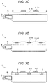
- FIGS. 3C to 3E are side views illustrating examples of structures where a groove or hole has been formed in the empty bobbin
- FIG. 4A is a perspective view of an iron core
- FIG. 4B is a perspective view illustrating an example of an assembled armature structure according to the embodiment
- FIG. 5 is a perspective view illustrating an assembled armature yoke structure according to the embodiment.
- FIG. 6A is a perspective view of an assembled printed board structure where a printed board has been assembled in the assembled armature yoke structure according to the embodiment, and FIG. 6B is a cross-sectional view;
- FIGS. 7A and 7B are side views illustrating a configuration where a base portion is affixed to the yoke.
- FIG. 8 is a cross-sectional view of a molded structure obtained from the state of FIG. 7A .
- An object of the present disclosure is to provide a bobbin structure of an armature where the insulation properties have been improved.
- a bobbin structure of an armature which is a bobbin structure of an armature where, in a three-phase motor having 6N (N is a natural number) slots of a motor armature, and 3N coils per phase, a main pole into which a winding bobbin around which a coil is wound is inserted, and an auxiliary pole into which an empty bobbin around which the coil is not wound is inserted are placed in a circumferential direction with respect to a rotation axis, characterized in that a contact portion where the empty bobbin and the winding bobbin are in contact with each other is formed on each of an outer peripheral side and an inner peripheral side of the slot formed between the main pole and the auxiliary pole.
- the contact portion where the empty bobbin and the winding bobbin are in contact with each other is formed to allow the empty bobbin to cover the winding bobbin. As a result, the insulation properties of the winding can be improved.
- the contact portion on the outer peripheral side of the slot, at least parts of the empty bobbin and the winding bobbin fit together, and the contact portion includes an opening portion.
- At least the parts fit together; accordingly, the movement of the empty bobbin and the winding bobbin in a direction extending in the rotation axis can be regulated. Moreover, the opening portion is provided. Accordingly, the heat transfer properties from the coil to the iron core can be improved.
- a groove or hole is formed on the outer peripheral side of the empty bobbin.
- a base portion which includes, at an end portion thereof, a base having a mounting surface where an end portion on an inner or outer diameter of a printed board is mounted, the base portion protruding from a side surface of the empty bobbin in a rotation axis direction.
- the base portion is provided which includes, at the end portion, the base where the end portion on the inner or outer diameter of the doughnut-shaped printed board is mounted. Accordingly, the position of the printed board can be determined.
- a tapered portion of a taper shape where the base portion tapers to an outer side in the rotation axis direction is provided on a surface opposite to the mounting surface of the base portion.
- the armature including the printed board and the base portion is integrally molded with resin
- the molded resin on the inner peripheral side of the printed board can be formed into a taper shape. Therefore, a component and the like can be placed in a space created by forming the taper shape.
- a bobbin structure of an armature where insulation properties is improved can be provided.
- a (winding) bobbin is a tube for forming a coil by winding an electric wire around the tube. This can be made of an insulating material. Moreover, an empty bobbin is a bobbin around which an electric wire (coil) is not wound.
- a periphery closer to a rotation axis C of a motor is referred to as the inner periphery, and a periphery farther from the rotation axis C is referred to as the outer periphery.
- a direction along the rotation axis is referred to as the rotation axis direction, and a direction extending radially with the rotation axis as the center is referred to as the radial direction.
- a rotating direction about the rotation axis is referred to as the circumferential direction.
- a side closer to the rotation axis with the rotation axis as the center is referred to as the inner peripheral side, and a side farther from the rotation axis is referred to as the outer peripheral side. In this manner, the positional relationship is described with reference to the rotation axis.
- the empty bobbin is used with a view to solving the above problems.
- FIG. 2 is a diagram illustrating an example of a cross-sectional structure taken along a plane where the rotation axis of an armature X of a motor is a normal.
- FIG. 2 is a diagram illustrating coils.
- a reference numeral C denotes the rotation axis of the motor.
- the armature X of the motor is, for example, a cylindrical armature where a rotor (mover) that rotates is placed on the inner peripheral side of the armature X.
- the number of slots (S) provided in an iron core 1 is 6N a natural number).
- the number of coils ( 3 ) is 3N.
- the number of coils is half the number of slots. Consequently, main poles 1 a into each of which a winding bobbin 2 around which the coil 3 is wound is inserted, and auxiliary poles 1 b into each of which an empty bobbin 4 around which the coil 3 is not wound is inserted are alternately placed in the iron core 1 .
- FIG. 3A is a perspective view of the empty bobbin according to the embodiment.
- FIG. 3B is a side view of the empty bobbin.
- a side wall portion 4 b provided on each side of a housing portion 4 a where the auxiliary pole 1 b is inserted and housed, and empty bobbin-side first flange portions 4 c configured in such a manner that the distance between the first flange portions 4 c increases gradually from the side wall portions 4 b toward the outer peripheral side with respect to the rotation axis C are formed on the empty bobbin 4 .
- the above gap 5 is formed between the first flange portion 4 c and the auxiliary pole 1 b.
- a winding-side first flange portion 2 a that covers the coil 3 is formed on the winding bobbin 2 on the outer peripheral side of the iron core 1 . Furthermore, a winding-side second flange portion 2 b that covers the coil 3 is also formed on the winding bobbin 2 on the inner peripheral side of the iron core 1 .
- a first contact portion where the first flange portion 4 c on the empty bobbin 4 side and the winding-side first flange portion 2 a of the winding bobbin 2 are in contact at their edge portions with each other is provided on the outer peripheral side of the iron core 1 .
- empty bobbin-side second flange portions 4 d that increase gradually in distance between them from the side wall portion 4 h of the empty bobbin 4 toward the inner diameter side of the iron core 1 are formed on the empty bobbin 4 .
- a second contact portion where the second flange portion 4 d on the empty bobbin 4 side and the winding-side flange portion 2 b of the winding bobbin 2 are in contact with each other by causing the flange portions 4 d and 2 b to overlap each other on their edge sides is provided on the inner peripheral side of the iron core 1 . Consequently, an improvement in the insulation performance between the coils is also promoted on the inner peripheral side.
- the second flange portion 4 d on the empty bobbin 4 side may be placed on the inner peripheral side with respect to the winding-side flange portion 2 b of the winding bobbin 2 . Consequently, it is possible to prevent the second flange portion 4 d on the empty bobbin 4 side from entering the inside of the coil 3 .
- the empty bobbin 4 allows the coil 3 to have a sufficient insulation distance from the auxiliary pole 1 b . Hence, the coil 3 will not have a ground fault.
- the insulation performance between the coils can be improved.
- the first flange portions 4 c are provided. Accordingly, the flange portions 4 c act perfectly as walls, and the inside of the motor is enclosed. As a result, the heat generated from the coil 3 results in keeping trapped in spaces of the winding bobbin 2 and the empty bobbin 4 .
- FIG. 3A is a perspective view of the empty bobbin according to the embodiment. Moreover, FIG. 3B is a side view of the empty bobbin.
- FIGS. 3C to 3E are side views illustrating examples of structures where a groove or hole has been formed in the empty bobbin.
- FIGS. 3A and 3B in the embodiment, grooves or holes are formed in advance in the edge portions of the first flange portions 4 c extending from the side wall 4 b of the empty bobbin 4 toward the outer peripheral side of the iron core 1 in the cross-sectional view of FIG. 2 in such a manner as to expand the width of the empty bobbin 4 .
- FIG. 3B illustrates an example where depressions and projections 4 c - 1 and 4 c - 2 are provided.
- FIG. 4A is a perspective view of the iron core.
- FIG. 4B is a perspective view illustrating an example of an assembled armature structure according to the embodiment. As illustrated in FIG. 4B , the wound winding bobbins 2 and the empty bobbins 4 have been alternately inserted into the iron core 1 (indicated with 1 a and 1 b ) illustrated in FIG. 4A .
- Depressed portions and projecting portions are alternately formed along the rotation axis C direction on each of depressions and projections 2 a - 1 and 2 a - 2 formed on the first flange portion 2 a of the winding bobbin 2 , and the edge portion of the first flange portion 4 c of the empty bobbin 4 .
- the first flange portion 2 a of the winding bobbin 2 and the depression and projection structures 4 c - 1 and 4 c - 2 on the first flange portion 4 c of the empty bobbin 4 fit together along the contact portion on the outer peripheral side. Consequently, the coil 3 is covered.
- the depth of the depression of the depressed portion 4 c - 1 formed in the first flange portion 4 c of the empty bobbin 4 can be increased as compared to the projection length of the projection of the projecting portion 2 a - 2 formed on the first flange portion 2 a of the winding bobbin 2 . Consequently, as illustrated in FIG. 4B , opening portions 8 can be formed after the bobbins are assembled.
- the projection-and-depression shape is provided on each of the winding bobbin 2 that is inserted into the main pole 1 a and the outer peripheral side of the empty bobbin 4 that is inserted into the auxiliary pole 1 b .
- the coil can be seen through the opening portion 8 in a state where the winding bobbin 2 and the empty bobbin 4 are mated as illustrated in FIG. 4B . Resin enters through the opening portion 8 and comes into intimate contact with the coil to ensure an improvement in thermal properties.
- the molding work such as cast molding or injection molding with varnish, resin, or the like may be performed after assembly of windings. Consequently, the resin composition flowing through the gap 5 as a passage comes into contact with both of the coil 3 and the auxiliary pole 1 b.
- the structure of the opening portion 8 may be configured as follows:
- FIGS. 3C to 3E are side views illustrating examples of structures where a groove or hole has been formed in the empty bobbin.
- a depressed portion 4 c - 1 a on the empty bobbin 4 side is made deeper than the projecting portion on the winding bobbin 2 side to form the opening portion 8 ( FIG. 3C ).
- a depressed portion 4 c - 1 b on the empty bobbin 4 side is formed as a multi-stepped depressed portion to form the opening portion 8 ( FIG. 3D ).
- a hole portion 9 is further formed into a window shape below the depression on the empty bobbin 4 side ( FIG. 3E ).
- a groove or hole is formed on the outer peripheral side of the empty bobbin 4 .
- a “groove or hole” is formed in a part of the contact portion on the outer peripheral side of the winding bobbin 2 and the empty bobbin 4 .
- the edge portions of the winding bobbin 2 and the empty bobbin 4 (the contact portion) can fit together along the rotation axis C direction. Consequently, the movement of the winding bobbin 2 and the empty bobbin 4 in the rotation axis C direction can be regulated. Therefore, the winding bobbin 2 and the empty bobbin 4 can be fixed in the rotation axis direction.
- FIG. 5 is a perspective view illustrating an example of an assembled armature yoke structure according to the embodiment.
- the structure illustrated in FIG. 5 is obtained by inserting the winding bobbins 2 into an armature yoke 6 in the state illustrated in FIG. 4B . Consequently, the assembly of an armature stator has been completed.
- FIG. 6A is a perspective view of an assembled printed board structure where a printed board has been assembled in the assembled armature yoke structure according to the embodiment.
- FIG. 6B is a cross-sectional view along line VIa-VIb in FIG. 6A .
- the structure illustrated in FIG. 6A is a structure where a printed board 7 is affixed to an end surface of the armature yoke 6 in the structure illustrated in FIG. 5 .
- resin molding can be performed in such a manner that molding resin is enabled to reach the coil in the assembled armature yoke structure.
- the opening portion is provided to allow improving the heat dissipation effect.
- the movement of the winding bobbin and the empty bobbin in the rotation axis direction can be regulated to fix the winding bobbin and the empty bobbin.
- a base portion 4 e protruding (extending) outward of the iron core 1 in the rotation axis C direction from a side surface of the empty bobbin 4 in the rotation axis C direction is formed as illustrated in FIGS. 3A and 3B .
- a base 4 g is formed on a distal end side of the base portion 4 e in the rotation axis C direction.
- a substantially flat mounting surface where an end portion on the inner or outer peripheral side of the doughnut-shaped printed board can abut and be mounted is provided on the base 4 g.
- the printed board 7 can be positioned by the mounting surface of the base 4 g provided at the end portion of the base portion 4 e of the empty bobbin in FIGS. 3A and 3B .
- Such a base portion 4 e allows determining the position of the inner or outer diameter of the doughnut-shaped printed board 7 .
- the empty bobbin 4 is provided with the base portion 4 e including the base 4 g for the printed board 7 . Accordingly, the base portion 4 e can be provided located on the outer peripheral side in the radial direction as illustrated in the cross-sectional views of FIGS. 6A and 6B .
- FIGS. 7A and 7B are side views illustrating a configuration where the base portion 4 e is affixed at one end of the yoke 6 .
- the base 4 g of the base portion 4 e is placed in such a manner that the position of the base 4 g is on the outer peripheral side with respect to an inner diameter P 1 of the core when the base portion 4 e is affixed to the yoke 6 .
- the inner diameter of the flat doughnut-shaped printed board 7 affixed to the base 4 g of the base portion 4 e can be increased as compared to the inner diameter of the core (the reference numeral C denotes the center line of the core, and P 1 denotes the inner diameter of the core; the same hereinafter).
- the above configuration allows increasing an inner periphery P 2 of the printed board 7 as compared to the inner diameter P 1 of the core.
- the inner diameter P 2 of the printed board 7 is increased as compared to the inner diameter P 1 of the core. Accordingly, the molding resin passage in the rotation axis C direction can be sufficiently secured.
- a component such as a bracket or bearing
- a molded resin portion 11 If the inner diameter of the core is large, a component (such as a bracket or bearing) can be placed below a molded resin portion 11 . Consequently, the entire length of the motor in the rotation axis C direction can be reduced.
- the inner diameter P 1 of the core can be reduced.
- the size of a bearing used is the same. If the inner diameter P 1 of the core is reduced as in the embodiment, it is difficult to place a bracket or the like below the molded resin 11 .
- a tapered portion 4 f of a taper shape where the width of the base portion 4 e in the radial direction is reduced toward the outer side in the rotation axis C direction, that is, the thickness is gradually reduced toward the outer side may be provided on a side opposite to the mounting surface of the base 4 g of the base portion 4 e as illustrated in FIG. 7A or 8 . Consequently, the tapered portion 15 can also be formed on the molded resin 11 .
- a component such as a bracket or bearing can be placed below the taper(ed portion) 15 . Consequently, the entire length of the motor can be reduced as compared to a case where a component such as a bracket or bearing is placed outward of the molded resin portion 11 in the rotation axis C direction.
- the base portion is provided on the winding bobbin side
- the area where a wire can be wound is reduced. If the windable area is reduced, a part where the winding overlap itself increases accordingly, which results in increasing the entire length of the motor.
- the base portion is provided to the winding bobbin, and if the base portion is not tapered, the winding is also molded straight in the molding process. Accordingly, the tapered portion cannot be formed on the molded resin. Therefore, a component such as a bracket or bearing ends up in being placed outward of the winding bobbin. As a result, the entire length of the motor increases (undesirably).
- the base portion 4 e is provided to the empty bobbin 4 around which the coil 3 is not wound. Hence, the base portion 4 e can be formed extending at any angle.
- the base portion 4 e is extended outward in the rotation axis C direction as the tapered portion 4 f of the base portion 4 e on the inner dimeter side of the iron core 1 . Accordingly, a lower part of the molded resin portion 11 also serves as the tapered portion 15 of a taper shape, Consequently, a component or the like can be placed below the tapered portion 15 . Therefore, the entire length of the motor can be reduced.
- the base portion 4 e is affixed in such a manner as to be symmetric about a line along the rotation axis C with respect to FIG. 7A as illustrated in FIG. 7B , the end portion on the outer peripheral side of the doughnut-shaped printed board 7 can be placed on the base 4 g .
- the tapered portion 4 f is formed on the outer dimeter side of the iron core 1 .
- the outer diameter of the printed board 7 can be reduced as compared to the outer diameter of the core.
- the tapered portion 15 is also formed on the molded resin on the basis of the tapered portion 4 f of the base portion 4 e . Hence, it is possible to prevent a component placed outward of the base portion 4 e in the rotation axis C direction from interfering with the molded resin portion 11 .
- the unwound empty bobbin is inserted into the auxiliary pole, the flange portions of both of the winding bobbin and the empty bobbin are caused to overlap each other. Consequently, an improvement in the insulation performance of the bobbin structure of the armature can be promoted. Furthermore, a groove or hole is provided in a part of the empty bobbin to integrally form the iron core and the winding with resin. Consequently, the heat transfer properties can be improved while the insulation distance between the coil and the magnetic pole is secured.
- the empty bobbin is provided with the base portion extending in the direction of the rotation axis of the motor to have the structure of holding the board.
- the degree of freedom is given to the inner diameter of the board. Accordingly, the resin passage can be secured.
- present disclosure is not limited to the illustrated configurations and the like in the above embodiments, and can be modified as appropriate within the scope that exerts the effects of the embodiments.
- present disclosure can be modified and carried oust as appropriate without departing from the scope of the object of the present disclosure.
- each constituent element of the embodiments can be freely selected, and a disclosure including the selected configuration is also included in the present disclosure.
- the bobbin structure of the armature is such a bobbin structure of an armature as described below, which is a bobbin structure of an armature where, in a three-phase motor having 6N (N is a natural number) slots of a motor armature, and 3N coils per phase, a main pole into which a winding bobbin around which a coil is wound is inserted, and an auxiliary pole into which an empty bobbin around which the coil is not wound is inserted are placed in a circumferential direction with respect to a rotation axis, characterized in that a contact portion where the empty bobbin and the winding bobbin are in contact with each other is formed on each of an outer peripheral side and an inner peripheral side of the slot formed between the main pole and the auxiliary pole.
- the present disclosure can be used for a bobbin structure of an armature.
Abstract
Description
Claims (11)
Applications Claiming Priority (3)
| Application Number | Priority Date | Filing Date | Title |
|---|---|---|---|
| JP2018240519A JP6694500B1 (en) | 2018-12-25 | 2018-12-25 | Armature bobbin structure |
| JP2018-240519 | 2018-12-25 | ||
| JPJP2018-240519 | 2018-12-25 |
Publications (2)
| Publication Number | Publication Date |
|---|---|
| US20200204031A1 US20200204031A1 (en) | 2020-06-25 |
| US11489392B2 true US11489392B2 (en) | 2022-11-01 |
Family
ID=68965691
Family Applications (1)
| Application Number | Title | Priority Date | Filing Date |
|---|---|---|---|
| US16/719,018 Active 2040-05-24 US11489392B2 (en) | 2018-12-25 | 2019-12-18 | Bobbin structure of armature |
Country Status (7)
| Country | Link |
|---|---|
| US (1) | US11489392B2 (en) |
| EP (1) | EP3675326B1 (en) |
| JP (1) | JP6694500B1 (en) |
| KR (1) | KR20200079430A (en) |
| CN (1) | CN111509891A (en) |
| ES (1) | ES2911470T3 (en) |
| TW (1) | TW202032586A (en) |
Families Citing this family (1)
| Publication number | Priority date | Publication date | Assignee | Title |
|---|---|---|---|---|
| DE102021003736A1 (en) | 2020-12-18 | 2022-06-23 | Hans Hermann Rottmerhusen | Electronically commutated electric motor |
Citations (10)
| Publication number | Priority date | Publication date | Assignee | Title |
|---|---|---|---|---|
| JPH08130844A (en) | 1994-11-02 | 1996-05-21 | Yaskawa Electric Corp | Armature of motor |
| JPH08182265A (en) | 1994-12-22 | 1996-07-12 | Yaskawa Electric Corp | Armature of electric rotary machine |
| US20040095035A1 (en) * | 2002-11-19 | 2004-05-20 | Fanuc Ltd. | Electric motor |
| US20060028087A1 (en) | 2004-08-09 | 2006-02-09 | A.O. Smith Corporation | Electric motor having a stator |
| US20090127972A1 (en) * | 2007-11-05 | 2009-05-21 | Mitsuba Corporation | Brushless motor |
| US20100052462A1 (en) * | 2008-09-04 | 2010-03-04 | Asmo Co., Ltd. | Armature and electric motor having the same |
| JP2010057277A (en) | 2008-08-28 | 2010-03-11 | Mitsuba Corp | Electric motor |
| US20140210303A1 (en) | 2013-01-31 | 2014-07-31 | Kabushiki Kaisha Yaskawa Denki | Bobbin and rotary electric machine |
| JP2015211563A (en) | 2014-04-28 | 2015-11-24 | 日立オートモティブシステムズ株式会社 | Stator of rotary electric machine and rotary electric machine including the same |
| US20180166932A1 (en) * | 2016-12-08 | 2018-06-14 | Robert Bosch Gmbh | Stator for a multiphase electric motor, method for producing a coil winding, and electric motor for a handheld tool |
Family Cites Families (2)
| Publication number | Priority date | Publication date | Assignee | Title |
|---|---|---|---|---|
| JP2006340511A (en) * | 2005-06-02 | 2006-12-14 | Mitsuba Corp | Brushless motor |
| JP6681249B2 (en) * | 2016-04-01 | 2020-04-15 | 株式会社ミツバ | Stator, manufacturing method thereof, and brushless motor |
-
2018
- 2018-12-25 JP JP2018240519A patent/JP6694500B1/en active Active
-
2019
- 2019-12-18 ES ES19217661T patent/ES2911470T3/en active Active
- 2019-12-18 KR KR1020190169421A patent/KR20200079430A/en not_active Application Discontinuation
- 2019-12-18 EP EP19217661.8A patent/EP3675326B1/en active Active
- 2019-12-18 US US16/719,018 patent/US11489392B2/en active Active
- 2019-12-23 CN CN201911335867.1A patent/CN111509891A/en active Pending
- 2019-12-24 TW TW108147378A patent/TW202032586A/en unknown
Patent Citations (11)
| Publication number | Priority date | Publication date | Assignee | Title |
|---|---|---|---|---|
| JPH08130844A (en) | 1994-11-02 | 1996-05-21 | Yaskawa Electric Corp | Armature of motor |
| JPH08182265A (en) | 1994-12-22 | 1996-07-12 | Yaskawa Electric Corp | Armature of electric rotary machine |
| US20040095035A1 (en) * | 2002-11-19 | 2004-05-20 | Fanuc Ltd. | Electric motor |
| US20060028087A1 (en) | 2004-08-09 | 2006-02-09 | A.O. Smith Corporation | Electric motor having a stator |
| US20090127972A1 (en) * | 2007-11-05 | 2009-05-21 | Mitsuba Corporation | Brushless motor |
| JP2010057277A (en) | 2008-08-28 | 2010-03-11 | Mitsuba Corp | Electric motor |
| US20100052462A1 (en) * | 2008-09-04 | 2010-03-04 | Asmo Co., Ltd. | Armature and electric motor having the same |
| US20140210303A1 (en) | 2013-01-31 | 2014-07-31 | Kabushiki Kaisha Yaskawa Denki | Bobbin and rotary electric machine |
| EP2763290A2 (en) | 2013-01-31 | 2014-08-06 | Kabushiki Kaisha Yaskawa Denki | Bobbin and rotary electric machine |
| JP2015211563A (en) | 2014-04-28 | 2015-11-24 | 日立オートモティブシステムズ株式会社 | Stator of rotary electric machine and rotary electric machine including the same |
| US20180166932A1 (en) * | 2016-12-08 | 2018-06-14 | Robert Bosch Gmbh | Stator for a multiphase electric motor, method for producing a coil winding, and electric motor for a handheld tool |
Non-Patent Citations (2)
| Title |
|---|
| Extended European Search Report (EESR) dated May 7, 2020 issued in the corresponding European Patent Application No. 19217661.8. |
| Japanese Office Action (JPOA) dated Dec. 3, 2019 issued in the corresponding Japanese Patent Application No. 2018-240519. |
Also Published As
| Publication number | Publication date |
|---|---|
| JP6694500B1 (en) | 2020-05-13 |
| US20200204031A1 (en) | 2020-06-25 |
| EP3675326A1 (en) | 2020-07-01 |
| EP3675326B1 (en) | 2022-03-16 |
| ES2911470T3 (en) | 2022-05-19 |
| CN111509891A (en) | 2020-08-07 |
| JP2020102972A (en) | 2020-07-02 |
| KR20200079430A (en) | 2020-07-03 |
| TW202032586A (en) | 2020-09-01 |
Similar Documents
| Publication | Publication Date | Title |
|---|---|---|
| JP5785863B2 (en) | Electric motor stator and permanent magnet rotating electric machine | |
| JP4655764B2 (en) | Rotating electric machine | |
| JP5306411B2 (en) | Rotating electric machine | |
| JP5681232B2 (en) | Electric motor stator injecting resin by injection molding | |
| JP5267091B2 (en) | Stator for rotating electrical machine | |
| JP2009232607A (en) | Winding for stator of rotating electric machine and rotating electric machine | |
| WO2015093157A1 (en) | Rotating electric machine | |
| JP5928904B2 (en) | Insulator, stator assembly, rotating electric machine, and wiring board | |
| JP5343625B2 (en) | Insulator for rotating electrical machine and stator for rotating electrical machine | |
| US11489392B2 (en) | Bobbin structure of armature | |
| JP2010141963A (en) | Stator | |
| JP2012222944A (en) | Stator | |
| JP5873262B2 (en) | Outer rotor type motor | |
| JP2006054963A (en) | Stepping motor | |
| JP2008220059A (en) | Armature and motor | |
| JP5271991B2 (en) | Rotating electric machine stator | |
| JPWO2022009521A5 (en) | Stator, rotating electrical machine, and manufacturing method for rotating electrical machine | |
| JP6595033B2 (en) | Axial air gap type rotating electrical machine | |
| JP6776850B2 (en) | Rotating machine | |
| JP2015211563A (en) | Stator of rotary electric machine and rotary electric machine including the same | |
| WO2021250903A1 (en) | Electric motor, blower device, and method for manufacturing electric motor | |
| WO2021205653A1 (en) | Electric motor stator and electric motor | |
| JP2005333752A (en) | Core unit of motor and coil unit | |
| US20200204015A1 (en) | Armature structure of three-phase motor | |
| JP2561135Y2 (en) | Armature for magnet generator |
Legal Events
| Date | Code | Title | Description |
|---|---|---|---|
| AS | Assignment |
Owner name: SANYO DENKI CO., LTD., JAPAN Free format text: ASSIGNMENT OF ASSIGNORS INTEREST;ASSIGNORS:HORIUCHI, MANABU;SAGARA, HIROKI;KITAJIMA, JUN;AND OTHERS;REEL/FRAME:051366/0204 Effective date: 20191217 |
|
| FEPP | Fee payment procedure |
Free format text: ENTITY STATUS SET TO UNDISCOUNTED (ORIGINAL EVENT CODE: BIG.); ENTITY STATUS OF PATENT OWNER: LARGE ENTITY |
|
| STPP | Information on status: patent application and granting procedure in general |
Free format text: APPLICATION DISPATCHED FROM PREEXAM, NOT YET DOCKETED |
|
| STPP | Information on status: patent application and granting procedure in general |
Free format text: DOCKETED NEW CASE - READY FOR EXAMINATION |
|
| STPP | Information on status: patent application and granting procedure in general |
Free format text: NON FINAL ACTION MAILED |
|
| STPP | Information on status: patent application and granting procedure in general |
Free format text: RESPONSE TO NON-FINAL OFFICE ACTION ENTERED AND FORWARDED TO EXAMINER |
|
| STPP | Information on status: patent application and granting procedure in general |
Free format text: FINAL REJECTION MAILED |
|
| STPP | Information on status: patent application and granting procedure in general |
Free format text: RESPONSE AFTER FINAL ACTION FORWARDED TO EXAMINER |
|
| STPP | Information on status: patent application and granting procedure in general |
Free format text: NOTICE OF ALLOWANCE MAILED -- APPLICATION RECEIVED IN OFFICE OF PUBLICATIONS |
|
| STPP | Information on status: patent application and granting procedure in general |
Free format text: PUBLICATIONS -- ISSUE FEE PAYMENT VERIFIED |
|
| STCF | Information on status: patent grant |
Free format text: PATENTED CASE |