US11485952B2 - Cell separation device and use of a flow formation for the cell separation device - Google Patents
Cell separation device and use of a flow formation for the cell separation device Download PDFInfo
- Publication number
- US11485952B2 US11485952B2 US16/077,588 US201716077588A US11485952B2 US 11485952 B2 US11485952 B2 US 11485952B2 US 201716077588 A US201716077588 A US 201716077588A US 11485952 B2 US11485952 B2 US 11485952B2
- Authority
- US
- United States
- Prior art keywords
- conduit
- axial
- configuration
- axial configuration
- segment
- Prior art date
- Legal status (The legal status is an assumption and is not a legal conclusion. Google has not performed a legal analysis and makes no representation as to the accuracy of the status listed.)
- Active, expires
Links
Images


Classifications
-
- C—CHEMISTRY; METALLURGY
- C12—BIOCHEMISTRY; BEER; SPIRITS; WINE; VINEGAR; MICROBIOLOGY; ENZYMOLOGY; MUTATION OR GENETIC ENGINEERING
- C12M—APPARATUS FOR ENZYMOLOGY OR MICROBIOLOGY; APPARATUS FOR CULTURING MICROORGANISMS FOR PRODUCING BIOMASS, FOR GROWING CELLS OR FOR OBTAINING FERMENTATION OR METABOLIC PRODUCTS, i.e. BIOREACTORS OR FERMENTERS
- C12M47/00—Means for after-treatment of the produced biomass or of the fermentation or metabolic products, e.g. storage of biomass
- C12M47/04—Cell isolation or sorting
Definitions
- the present invention relates to a cell separation apparatus, encompassing a container for reception of a cell suspension and a conduit connected to the container for the conveyance of cell suspension out of the container, the conduit extending along a notional conduit path passing centrally through the conduit, the conduit path defining in the conduit an axial direction proceeding along the conduit path, a radial direction orthogonal to the conduit path, and a circumferential direction proceeding around the conduit path, at least a segment of the conduit, constituting a turbulent flow segment, comprising a flow configuration that generates a turbulent cell suspension flow.
- the present invention further relates to use of a flow configuration in order to separate cells in a cell suspension.
- a cell separation apparatus of the species is known from WO 2008/067044 A.
- a fundamental problem with cell cultures is that the cultured cells present in a cell suspension after being harvested are often not present in completely separated fashion, but exist in part as cell clusters or cell agglomerations in which several cells are joined to one another.
- cell clusters or cell agglomerations in cell suspensions thus result in differences in the development of cells in cell culture; as a rule, cell agglomerations disadvantageously influence the cell culture yield.
- Cell mortality in cell agglomerations furthermore rises compared with the cell mortality of individual cells.
- a disadvantage of the known flow configuration of the cell separation apparatus of the species is its small flowthrough cross section, since in order to achieve the desired degree of turbulence the known flow obstacles exhibit, in the least obstructive case, only 50% of the flow cross section of the conduit conveying the cell suspension without a flow configuration.
- the hole pattern of the known flow obstacles can be constricted to the point that the passthrough cross section of the flow obstacles is equal to only 1% of the flow cross section of the flow-conveying conduit without a flow configuration.
- the object of the present invention is therefore to describe a technical teaching that, in a context of at least the same separation success and for the same flow-capable conduit cross section without a flow configuration, permits a higher volumetric throughput per unit time, thereby demonstrably increasing the cost-effectiveness of the cell separation apparatus.
- the flow configuration comprises at least two axial configuration segments located axially behind one another, one of which is embodied to accelerate a cell suspension, flowing through the conduit axially away from the container, in a circumferential direction in a first directional orientation, and the respective other of which is embodied to accelerate the cell suspension in a circumferential direction in a second directional orientation opposite to the first directional orientation.
- this object is also achieved by the use of a flow configuration that extends along a notional configuration path passing centrally through the flow configuration, the configuration path defining an axial direction proceeding along the configuration path, a radial direction orthogonal to the configuration path, and a circumferential direction proceeding around the configuration path, the flow configuration comprising at least two axial configuration segments located axially behind one another, of which the one axial configuration segment is embodied to accelerate a fluid, flowing through the conduit axially away from the container, in a circumferential direction in a first directional orientation, and of which the respective other axial configuration segment is embodied to accelerate the fluid in a circumferential direction in a second directional orientation opposite to the first directional orientation, to separate cells in a cell suspension constituting the flowing fluid.
- conduit path and configuration path in fact proceed collinearly in the operationally ready cell separation apparatus. But because the use claim is directed toward the use of a flow configuration on its own, what is used here instead of the conduit-based coordinate system is the coordinate system, referred directly to the flow configuration, of the configuration path.
- the basic idea of the present invention is that of accelerating the axial flow in the conduit, additionally to the axial motion, to perform oppositely directed circumferential motions as a result of the axial configuration segments located axially behind one another.
- An aperture plate, as used in the existing art of the species, can thereby be omitted. A sufficient degree of turbulence can thus be achieved without the cross-sectional constrictions of the flow cross section which are typical of the aperture plate of the existing art.
- the cell separation apparatus of the existing art achieves the degree of turbulence in an axially very short space using two axially successive aperture plates, but the placement space available between the container and the conduit end, remote from the container, of the conduit as a rule is not critical, especially since the conduit does not need to proceed in extended fashion, i.e. with a rectilinear conduit path, but can instead be wound into a coil, spiral, and the like.
- the cell separation apparatus therefore requires a longer axial conduit segment than the apparatus of the existing art of the species in order to achieve a high degree of turbulence, but this can be achieved with a cross-sectional reduction in the flow cross section of the conduit which, compared with the identical conduit without a flow configuration, does not exceed 15%, preferably 10%, of the identical flow cross section without a flow configuration.
- a substantially larger quantity of cell suspension per unit time can therefore be made turbulent, and the cells contained therein can thus be reliably separated.
- the slightly longer axial conformation of the conduit is therefore more than compensated for by the considerably elevated volumetric throughput per unit time.
- the intention here is that axially successive axial configuration segments be embodied to accelerate the cell suspension, flowing in principle axially through the conduit, in opposite circumferential directions.
- the result is to achieve, in the cell suspension, turbulence which is sufficient for separation of the cell agglomerates possibly contained therein. This is furthermore achieved in particularly gentle fashion, which has an advantageous effect on cell viability.
- Many cells have little capacity for mechanical loads, especially as caused by shear loads that often occur in flows (shear stress).
- a high degree of turbulence is achieved without undesirably high shear loads.
- the separation result determined e.g. by the number of cell agglomerates contained in a predetermined quantity of cell suspension after passage through the flow configuration as compared with the number thereof before passing through the flow configuration, is outstanding.
- the consequence of the oppositely directed circumferential accelerations can be that as the cell suspension flows through the turbulent flow segment it flows, always in the same directional orientation but at different speeds, in a circumferential direction.
- the at least two axial configuration segments located axially behind one another are embodied to impart to the cell suspension flowing axially through them, in an upstream axial configuration segment, a flow component proceeding in a circumferential direction in a first directional orientation, and to impart to the cell suspension, in a downstream axial configuration segment, a flow component proceeding in a second directional orientation opposite to the first directional orientation.
- the flow component of the cell suspension in a circumferential direction changes not only in terms of quantity but also in terms of its directional orientation.
- the flow of fluid or cell suspension also impinges axially on the axial configuration segments, i.e. has, in addition to the axial flow component, flow components in other flow directions (radially and/or in a circumferential direction).
- the flow in the conduit or through the flow configuration does not need to be exclusively axial at any point.
- the separation result can be improved, while cell viability remains high, by the fact that the axial length of the flow configuration, and the number of directional orientation changes in the acceleration of the flow in a circumferential direction which take place over that axial length, are increased.
- the flow configuration comprises a plurality of axial configuration segments located axially behind one another, of which each axial configuration segment axially succeeding another axial configuration segment is embodied to accelerate the cell suspension, flowing through the conduit in an axial direction away from the container, in a circumferential direction in a directional orientation which is directed oppositely from the directional orientation of the acceleration in a circumferential direction in the axially immediately preceding axial configuration segment.
- An “axial configuration segment” for purposes of this Application is always intended to be an axial segment of the flow configuration in which the suspension flow is accelerated in a circumferential direction in a uniform directional orientation.
- a new axial configuration segment begins, and it extends axially until the directional orientation of the acceleration of the suspension flow in a circumferential direction reverses again.
- each axial configuration segment axially succeeding another axial configuration segment is embodied to impart to the cell suspension flowing through the conduit in an axial direction away from the container a flow component, proceeding in a circumferential direction, whose circumferential directional orientation is directed oppositely to that in the axially immediately preceding axial configuration segment.
- the flow configuration preferably encompasses at least eight axial configuration segments.
- an axial flow in a conduit can be equipped with a flow component in a circumferential direction, i.e. can be accelerated or deflected in a circumferential direction.
- Any type of flow influence that, in axially successive axial configuration segments, accelerates the cell suspension in a circumferential direction in opposite directional orientations is suitable for achieving the result according to the present invention.
- the flow configuration can therefore physically comprise, in at least two axial configuration segments, at least one respective directing surface that is inclined with respect to the conduit path in such a way that the normal vector of the directing surface, by definition pointing away from the directing surface, on the one hand has an axial component that points in an axial direction toward that longitudinal end of the conduit which is closer to the container and from which the cell suspension flows, and has a circumferential component that points in a circumferential direction.
- the circumferential components of the normal vectors of directing surfaces of axial configuration segments located axially behind one another point in opposite directions.
- the flow configuration comprises at least one such directing surface preferably in more than two axial configuration segments, particularly preferably in each of its axial configuration segments.
- the directing surface can be a flat surface that can be set with reference to the conduit path at a setting angle around a setting axis that proceeds in a radial direction.
- the setting axis can, but does not need to, intersect the conduit path, but can also proceed at a distance from it.
- the directing surface can be rotated around a rotation axis parallel to the conduit path, in particular in such a way that the normal vector of the directing surface also has a component radially inward toward the conduit path.
- the setting angle of the directing surface is no greater than 45° with respect to a plane at the same point containing the conduit path, so that the dynamic pressure at the inflow end of an axial configuration segment is not unnecessarily raised.
- the setting angle of a directing surface in an axial configuration segment can become larger with increasing axial distance from the axial inflow end, so that with increasing axial distance from the inflow end, the flow component in a circumferential direction in the relevant axial configuration segment becomes increasingly greater.
- the directing surface can then be constituted from a plurality of flat surface segments, each two of which that directly succeed one another in a circumferential direction are angled with respect to one another.
- the setting angle can, however, also be constant over the axial length of an axial configuration segment, or can also be constant over the axial length of the entire flow configuration over all the directing surfaces.
- the directing surface of an axial configuration segment can extend radially inward beyond the conduit path, proceeding from a conduit wall that radially externally delimits the flow region of the conduit.
- at least one axial configuration segment of the flow configuration comprises at least two directing surfaces.
- the two directing surfaces are then respectively arranged in the same axial region of the conduit, respectively in a radial region between the conduit path and conduit wall but in different circumferential regions.
- a plurality of axial configuration segments, particularly preferably each axial configuration segment of the flow configuration is embodied in such a way.
- the two or more directing surfaces of an axial configuration segment are preferably embodied symmetrically with respect to the conduit path in such a way that the one directing surface is transformable, by rotation around the conduit path, into a respective other directing surface of the same axial configuration segment.
- the at least one directing surface of an axial configuration segment can be embodied helically.
- the directing surfaces of an axial configuration segment are embodied helically.
- the pitch angle of the helical directing surface is defined by a plane tangent to the directing surface, which is curved as a result of its helical configuration.
- the pitch angle can in turn increase toward the axial outflow end with increasing axial distance from the axial inflow end of the axial configuration segment.
- the pitch angle is constant over the entire axial length of the directing surface.
- the pitch angles of a directing surface, in particular of all directing surfaces are constant over the entire axial length of an axial configuration segment.
- the pitch angles of all directing surfaces of all axial configuration segments are of constant magnitude and identical in size, and differ between the different axial configuration segments only in terms of their differing sign, in order to be able to provide, due to their differing pitch, the acceleration of the suspension flow in a circumferential direction in opposite directional orientations.
- the helical directing surface of an axial configuration segment can encircle the notionally central conduit path or configuration path any number of times.
- the helical directing surface extends along its axial dimension exactly sufficiently far in a circumferential direction around the conduit path that the suspension flowing along it has an unequivocal acceleration, or even motion, imparted to it before the flow flows into the axially successive axial configuration segment and is accelerated, or even moved, therein in a circumferential direction in the opposite directional orientation.
- the acceleration of a portion of the total cell suspension flow approximately 60% of the mass flow or more, in a circumferential direction is sufficient in this context.
- the helical directing surface sweeps out along its axial extent at least, preferably exactly, an angle of 180° around the conduit path. This applies preferably to all directing surfaces of a given axial configuration segment.
- a particularly low-loss flow axially through the conduit and along the flow configuration can be achieved, in the context of an axial sequence of axial configuration segments acting acceleratingly in a circumferential direction in opposite directional orientations, by the fact that the axially inflow-side edge of a directing surface of one axial configuration segment is arranged with an offset, preferably arranged with a 90° or 180° offset, in a circumferential direction with respect to the axially outflow-side edge of a directing surface of the immediately preceding (upstream) axial configuration segment.
- the conduit is constituted from comparatively flexible silicone plastic.
- Silicone plastic of this kind permits, after curing, nondestructive unmolding of a mold core, constituting the flow configuration radially internally in the conduit, in an axial direction in which the cell suspension ultimately also flows through the conduit during operation.
- the directing surfaces of the axial configuration segments can project radially inward from the conduit wall; they do not necessarily need to proceed radially inward as far as the center of the conduit, i.e. to the location of the virtual conduit path.
- the flow configuration is embodied on a configuration component embodied separately from the conduit.
- This on the one hand has an advantage in terms of production engineering, since a configuration component of this kind, constituting a separate component, can be manufactured substantially more simply and inexpensively, and with greater design freedom, than a flow configuration extending in one piece radially inside the conduit.
- a suitable configuration component constituting a mixer component for effective blending of two components of a mixed product, is known from DE 20 2012 002 102 U1.
- the configuration component is used to mix different liquid components, according to the present invention it is used to separate cell agglomerations in a liquid.
- a further advantage of separate embodiment of the configuration component is the considerably improved capability for cleaning and optionally sterilizing the conduit and flow configuration after use, so that the conduit and flow component can be used again for a different cell suspension with no risk of contamination of the cell suspension by the conduit and flow configuration as a result of previous use.
- the configuration component is preferably deformable so that it is introducible even into a physically long conduit that does not proceed rectilinearly.
- the conduit is preferably helically coiled in order to achieve the longest possible axial turbulence length, so that it is particularly advantageous for the configuration component if it is flexible, in particular around one or several flexure axes that enclose an angle with the conduit path.
- the angle between the flexure axes and the conduit path is preferably a right angle.
- the conduit is preferably also deformable, so that depending on the application it can be brought, respectively within the context of its deformability, into a suitable shape.
- the configuration component is preferably manufactured as an injection-molded component, the deformability then advantageously being adjustable by way of the material thickness of the directing structure comprising the directing surfaces.
- the configuration component can comprise a support structure extending at least along an axial segment of the flow configuration, preferably axially along the entire flow configuration, with which the directing surfaces are connected, preferably connected in one piece, at their radially inner end.
- the supporting structure is preferably a central rod structure or column structure, consequently a core of the configuration component, whose radial dimension is preferably smaller than the radial dimension of the flow configuration in order to avoid unnecessary flow obstacles.
- Cell separation using the apparatus according to the present invention can advantageously be accomplished in a completely closed system, with no contact occurring between the cell suspension and the atmosphere.
- a collection container, into which the cell suspension having the separated cells is delivered, can be arranged at the downstream end of the conduit.
- FIG. 1 schematically depicts, by way of an embodiment according to the present invention, a cell separation apparatus of the present Application in longitudinal section;
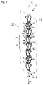
- FIG. 2 is a perspective view of the configuration component used in the cell separation apparatus of FIG. 1 .
- FIG. 1 an embodiment according to the present invention of a cell separation apparatus of the present Application is labeled in general with the number 10 . It encompasses a container 12 , for example a cell culture container, only a corner region of which is depicted in the schematic longitudinal section of FIG. 1 .
- a container 12 for example a cell culture container, only a corner region of which is depicted in the schematic longitudinal section of FIG. 1 .
- Container 12 is adjoined by a conduit 14 , for example a flexible hose conduit 14 .
- Hose conduit 14 is coupled to an outlet configuration 16 of cell culture container 12 and retained in position there, in particular against being pulled out of outlet configuration 16 , by means of a threaded retainer 18 .
- Outlet configuration 16 is depicted merely schematically in FIG. 1 .
- conduit 14 is permanently coupled to outlet configuration 16 .
- Conduit 14 can also be insertable, and thus quickly connectable and releasably couplable to outlet configuration 16 , via attachment or coupling configurations known per se.
- An insertable connection of this kind can at least be established and undone more quickly than is the case using threaded retainer 18 .
- the nature of the flow connection between conduit 14 and an outlet opening 20 , surrounded by outlet configuration 16 , of cell culture container 12 is, however, not relevant in the present case.
- a valve arrangement 24 acting in known fashion, by way of which a flow connection between conduit 14 and outlet opening 20 can be selectably established or blocked, can be arranged in region 24 in attachment configuration 16 outlined with dashed lines, and also in conduit 14 .
- Valve arrangement 24 can be switchable, in a manner known per se, in contactless fashion by magnetic field manipulation from outside outlet configuration 16 , for example by modifying a magnetic field acting on valve arrangement 24 from outside outlet configuration 16 , with the result that a ferromagnetic valve body can be displaceable between a flowthrough position and a blocking position.
- cell culture container 12 serves for the culturing of adherent cells that initially grow adheringly on a culture surface in cell culture container 12 and detach from their culture surfaces after addition of a corresponding dissolution agent to the liquid present in cell container 12 , so that the cells can then float freely in the liquid in cell culture container 12 and thus form, together with the liquid in cell culture container 12 , a cell suspension.
- the cells dissolved in the cell suspension are ready to harvest and are usually removed from cell culture container 12 , in the present example through outlet opening 20 , shortly after detachment from their culture surfaces.
- a flow configuration 26 constituted in the example depicted by a configuration component 28 embodied separately from conduit 14 and arranged therein, is provided in conduit 14 in order to separate the cells out of the undesired cell agglomerations.
- Configuration component 28 is also depicted in isolation, in perspective, in FIG. 2 .
- flow configuration 26 can in fact be arranged at any desired point in conduit 14 . Additional conduits (not depicted in FIG. 1 ) can furthermore be interposed between conduit 14 and outlet configuration 16 .
- Conduit 14 which is likewise depicted for the sake of simplicity as a rectilinear conduit 14 , extends along a notional conduit path L passing through centrally along a flowthrough-capable conduit cavity 30 . Because flow configuration 26 is arranged in conduit 14 collinearly therewith, conduit path L is at the same time also configuration path F, along which flow configuration 26 and configuration component 28 extend (see also FIG. 2 ).
- Flow configuration 26 is flexible and can be curved around any flexure axes. It can in particular be rolled up in space-saving fashion into a coil and the like.
- Flow configuration 26 serves in the present case, along its extent, as a turbulent flow segment 32 of conduit 14 in order to provide, at least in that turbulent flow segment 32 , a turbulence that separates the cell agglomerations in the cell suspension flowing through it.
- Flow configuration 26 comprises for that purpose several axial configuration segments arranged axially behind one another, of which only axial configuration segments 34 and 36 , which are arranged in flow configuration 26 alternatingly in an axial direction, will be explained in further detail below.
- Conduit path L and configuration path F define an axial direction A. They furthermore define a radial direction R orthogonal to the axial direction, and a circumferential direction U surrounding the respective paths L and F.
- the natural directional orientation of axial direction A is directed away from cell culture container 12 .
- the natural directional orientation of radial direction R is directed away from the respective path L or F, and the natural directional orientation of the circumferential direction is counter-clockwise when viewed in the natural axial direction.
- Axial configuration segments 34 and 36 that alternate successively in axial direction A serve to accelerate a cell suspension, which flows axially through turbulent flow segment 32 , in circumferential direction U alternatingly in opposite directional orientations.
- Section plane SE along which flow configuration 26 or configuration component 28 is shown sectioned in FIG. 1 , is depicted with dot-dash lines in FIG. 2 .
- Section plane SE contains configuration path F.
- Axial configuration segments 34 are embodied to accelerate a cell suspension, which flows in the natural axial direction A through conduit 14 or flow configuration 26 , in circumferential direction U in the natural directional orientation, i.e. counter-clockwise when viewed in the natural axial direction.
- Axial configuration segments 36 are embodied to accelerate the cell suspension flowing through them in the circumferential direction in the opposite directional orientation, i.e. clockwise when viewed in the natural directional orientation of axial direction A.
- Both axial configuration segments 34 and axial configuration segments 36 have respective directing surfaces 40 a and 40 b for this purpose.
- Directing surfaces 40 a and 40 b which respectively extend radially outward from configuration path F, proceed in helical fashion with mutually opposite twists.
- both axial configuration segments 34 and axial configuration segments 36 respectively comprise a second directing surface in addition to directing surface 40 a and 40 b , but it always faces away from the viewer in FIG. 2 .
- the two directing surfaces of each axial configuration segment 34 or 36 are constructed symmetrically with respect to one another in such a way that they are transformable into one another by rotation around configuration path F, in each case by a 180° rotation in the example depicted.
- directing surfaces 40 a and 40 b thus also applies to the respective second directing surface of the same respective axial configuration segment 34 and 36 .
- a portion of second directing surface 42 a of axial configuration segments 34 is visible only in FIG. 1 .
- the helical directing surfaces 40 a , 42 a , and 40 b , as well as the further directing surface (not visible) of axial configuration segment 36 have over their axial extent a constant pitch angle ⁇ that is of the same magnitude for both axial configuration segments 34 and 36 , and is merely directed oppositely.
- the helical directing surface 40 a thus has a normal vector N that has an axial component Na that points axially in the direction from which flow impinges on the directing surface, and has a component Nu that points in a circumferential direction in the directional orientation in which the flow striking directing surface 40 a is accelerated.
- Directing surfaces 40 b also have normal vectors M whose axial component Ma is identical in terms of magnitude and direction with respect to the axial component Na of normal vector N of directing surface 40 a .
- Circumferential directional component Mu of normal vector M of directing surface 40 b is furthermore identical in magnitude, but oppositely directed, with respect to circumferential directional component Nu of normal vector N of directing surface 40 a . Acceleration of the cell suspension flowing through axial configuration segments 34 and 36 in circumferential direction U in opposite directional orientations is thereby obtained.
- the directing surfaces of a given axial configuration segment respectively extend 180° in a circumferential direction, and thus constitute half a basic screw thread.
- the two directing surfaces of a given axial configuration segment are arranged with a 180° offset from one another in a circumferential direction, they form, orthogonally to configuration path F, both a rectilinear axially inflow-side edge 44 a for axial configuration segments 34 and 44 b for axial configuration segments 36 , and, orthogonally to configuration path F, a rectilinear axially outflow-side edge 46 a for axial configuration segments 34 and 46 b for axial configuration segments 36 .
- the axially inflow-side edges 44 a and 44 b of a first axial configuration segment 34 or 36 are preferably rotated 90° in terms of the respective axially outflow-side edges 46 b and 46 a of a second axial configuration segment 36 or 34 immediately axially preceding the first axial configuration 34 or 36 .
- a pump is not depicted in FIG. 1 , even though a conveying pump for generating a flow of cell suspension flowing axially through conduit 14 away from cell culture container 12 can be present.
- a pump is not obligatorily necessary, however.
- a flow of cell suspension through conduit 14 past flow configuration 26 can be gravity-induced.
- the flow can be generated by generating an excess pressure in a gas bladder in cell culture container 12 , so that the excess gas pressure in cell culture container 12 expels the cell suspension out of container 12 via outlet opening 20 through conduit 14 .
- turbulent flow segment 32 can be axially prolonged by arranging several flow configurations 26 or several configuration components 28 behind one another in a conduit 14 , thereby extending the turbulence path length traveled by the cell suspension.
- Configuration component 28 can be retained axially in position in conduit 14 in positively engaging fashion, for example by an interaction of projections and recesses, and/or intermaterially, for example using adhesive.
- a frictional engagement between the inner wall of conduit 14 and the outer edge of configuration component 28 is already sufficient to prevent an axial displacement of configuration component 28 relative to conduit 14 as flow occurs through conduit 14 .
- the frictional engagement becomes that much more sufficient as conduit 14 is arranged with a greater curvature, for example in the above-described helical shape for space-saving arrangement even of longer conduit segments.
- conduit carrying the cell suspension is always to be conceived of as a rectilinear conduit along a rectilinear conduit path, even though in reality that is technically not obligatorily necessary.
Landscapes
- Life Sciences & Earth Sciences (AREA)
- Engineering & Computer Science (AREA)
- Health & Medical Sciences (AREA)
- Chemical & Material Sciences (AREA)
- Wood Science & Technology (AREA)
- Biotechnology (AREA)
- Bioinformatics & Cheminformatics (AREA)
- Organic Chemistry (AREA)
- Zoology (AREA)
- Biomedical Technology (AREA)
- Sustainable Development (AREA)
- Microbiology (AREA)
- Cell Biology (AREA)
- Biochemistry (AREA)
- General Engineering & Computer Science (AREA)
- General Health & Medical Sciences (AREA)
- Genetics & Genomics (AREA)
- Molecular Biology (AREA)
- Apparatus Associated With Microorganisms And Enzymes (AREA)
Abstract
Description
Claims (19)
Applications Claiming Priority (3)
| Application Number | Priority Date | Filing Date | Title |
|---|---|---|---|
| DE102016202139.7 | 2016-02-12 | ||
| DE102016202139.7A DE102016202139A1 (en) | 2016-02-12 | 2016-02-12 | Cell separation device and use of a flow formation to the cell separation device |
| PCT/EP2017/052812 WO2017137472A1 (en) | 2016-02-12 | 2017-02-09 | Cell separation device and use of a flow formation for the cell separation device |
Publications (2)
| Publication Number | Publication Date |
|---|---|
| US20190032002A1 US20190032002A1 (en) | 2019-01-31 |
| US11485952B2 true US11485952B2 (en) | 2022-11-01 |
Family
ID=58054095
Family Applications (1)
| Application Number | Title | Priority Date | Filing Date |
|---|---|---|---|
| US16/077,588 Active 2038-04-21 US11485952B2 (en) | 2016-02-12 | 2017-02-09 | Cell separation device and use of a flow formation for the cell separation device |
Country Status (4)
| Country | Link |
|---|---|
| US (1) | US11485952B2 (en) |
| EP (1) | EP3414548B1 (en) |
| DE (1) | DE102016202139A1 (en) |
| WO (1) | WO2017137472A1 (en) |
Families Citing this family (5)
| Publication number | Priority date | Publication date | Assignee | Title |
|---|---|---|---|---|
| WO2026022007A1 (en) | 2024-07-24 | 2026-01-29 | Hamilton Bonaduz Ag | Cell culture container operating device for securely detachably receiving a cell culture container during cell culture management |
| DE102024121072A1 (en) | 2024-07-24 | 2026-01-29 | Hamilton Bonaduz Ag | Tumble device for a cell culture management device for wetting surfaces in a cell culture container |
| DE102024121067A1 (en) | 2024-07-24 | 2026-01-29 | Hamilton Bonaduz Ag | Cell culture management device with a valve block arrangement having at least two separately designed valve blocks |
| DE102024121069A1 (en) | 2024-07-24 | 2026-01-29 | Hamilton Bonaduz Ag | Media container system for a cell culture management device |
| DE102024121070A1 (en) | 2024-07-24 | 2026-01-29 | Hamilton Bonaduz Ag | Cell culture management device with media transfer between cell culture containers and method for media transfer between cell culture containers |
Citations (14)
| Publication number | Priority date | Publication date | Assignee | Title |
|---|---|---|---|---|
| US3794300A (en) * | 1971-12-30 | 1974-02-26 | Dow Badische Co | Annular spiral isg |
| US4840493A (en) * | 1987-11-18 | 1989-06-20 | Horner Terry A | Motionless mixers and baffles |
| US5069881A (en) * | 1990-07-10 | 1991-12-03 | Mobay Corporation | Device and method for applying adhesives |
| DE4435717A1 (en) | 1994-07-06 | 1996-01-11 | Hennecke Gmbh Maschf | Process for the continuous dispersion of finely divided solids in a liquid |
| US6840281B1 (en) * | 2001-11-06 | 2005-01-11 | Vent-Matic Company, Inc. | Liquid flow pressure reducer and method |
| US20050106452A1 (en) * | 2003-07-28 | 2005-05-19 | Qureshi Nawaz M. | Acid stripper |
| US7041218B1 (en) * | 2002-06-10 | 2006-05-09 | Inflowsion, L.L.C. | Static device and method of making |
| WO2008019964A1 (en) | 2006-08-15 | 2008-02-21 | Basf Se | Method for isolating proteins from production cells |
| WO2011043731A1 (en) | 2009-10-09 | 2011-04-14 | Georgia Tech Research Corporation | Method and device for dispersion of assemblies of biological material |
| US20130078163A1 (en) | 2011-09-22 | 2013-03-28 | Georgia Tech Research Corporation | Deterministic High-Density Single-Cell Trap Array |
| DE202012002102U1 (en) | 2012-03-02 | 2013-06-04 | Udo Tartler | Device for mixing at least two fluid components, rotary driven mixer insert therefor and system of both |
| US20130205729A1 (en) * | 2012-02-13 | 2013-08-15 | Nawaz M. Qureshi | Acid Stripper |
| DE102013200927A1 (en) | 2013-01-22 | 2014-07-24 | Siemens Aktiengesellschaft | Method for enriching and separating cells with concentrations over several logarithmic stages |
| WO2015158776A1 (en) | 2014-04-15 | 2015-10-22 | Boehringer Ingelheim International Gmbh | Methods, apparatuses, and systems for continuously inactivating a virus during manufacture of a biological product |
Family Cites Families (1)
| Publication number | Priority date | Publication date | Assignee | Title |
|---|---|---|---|---|
| SI2076157T1 (en) | 2006-10-11 | 2018-12-31 | Merial, Inc. | Dispersion devices for aggregates |
-
2016
- 2016-02-12 DE DE102016202139.7A patent/DE102016202139A1/en not_active Withdrawn
-
2017
- 2017-02-09 WO PCT/EP2017/052812 patent/WO2017137472A1/en not_active Ceased
- 2017-02-09 US US16/077,588 patent/US11485952B2/en active Active
- 2017-02-09 EP EP17705566.2A patent/EP3414548B1/en active Active
Patent Citations (18)
| Publication number | Priority date | Publication date | Assignee | Title |
|---|---|---|---|---|
| US3794300A (en) * | 1971-12-30 | 1974-02-26 | Dow Badische Co | Annular spiral isg |
| US4840493A (en) * | 1987-11-18 | 1989-06-20 | Horner Terry A | Motionless mixers and baffles |
| US5069881A (en) * | 1990-07-10 | 1991-12-03 | Mobay Corporation | Device and method for applying adhesives |
| DE4435717A1 (en) | 1994-07-06 | 1996-01-11 | Hennecke Gmbh Maschf | Process for the continuous dispersion of finely divided solids in a liquid |
| US6840281B1 (en) * | 2001-11-06 | 2005-01-11 | Vent-Matic Company, Inc. | Liquid flow pressure reducer and method |
| US7041218B1 (en) * | 2002-06-10 | 2006-05-09 | Inflowsion, L.L.C. | Static device and method of making |
| US20050106452A1 (en) * | 2003-07-28 | 2005-05-19 | Qureshi Nawaz M. | Acid stripper |
| US20090233348A1 (en) | 2006-08-15 | 2009-09-17 | Basf Se | Method for isolating proteins from production cells |
| WO2008019964A1 (en) | 2006-08-15 | 2008-02-21 | Basf Se | Method for isolating proteins from production cells |
| WO2011043731A1 (en) | 2009-10-09 | 2011-04-14 | Georgia Tech Research Corporation | Method and device for dispersion of assemblies of biological material |
| US20120258536A1 (en) | 2009-10-09 | 2012-10-11 | Swetree Technologies Ab | Method and device for dispersion of assemblies of biological material |
| US20130078163A1 (en) | 2011-09-22 | 2013-03-28 | Georgia Tech Research Corporation | Deterministic High-Density Single-Cell Trap Array |
| US20130205729A1 (en) * | 2012-02-13 | 2013-08-15 | Nawaz M. Qureshi | Acid Stripper |
| DE202012002102U1 (en) | 2012-03-02 | 2013-06-04 | Udo Tartler | Device for mixing at least two fluid components, rotary driven mixer insert therefor and system of both |
| DE102013200927A1 (en) | 2013-01-22 | 2014-07-24 | Siemens Aktiengesellschaft | Method for enriching and separating cells with concentrations over several logarithmic stages |
| US20150355072A1 (en) | 2013-01-22 | 2015-12-10 | Siemens Aktiengesellschaft | Method for Enriching and Isolating Cells Having Concentrations Over Several Logarithmic Steps |
| WO2015158776A1 (en) | 2014-04-15 | 2015-10-22 | Boehringer Ingelheim International Gmbh | Methods, apparatuses, and systems for continuously inactivating a virus during manufacture of a biological product |
| US20170037381A1 (en) | 2014-04-15 | 2017-02-09 | Boehringer Ingelheim International Gmbh | Methods, apparatuses, and systems for continuously inactivating a virus during manufacture of a biological product |
Non-Patent Citations (3)
| Title |
|---|
| English language machine translation of DE 202012002102 U1, generated Feb. 3, 2021. (Year: 2021). * |
| German Search Report issued in DE 10 2016 202 139.7. |
| International Search Report issued in PCT/EP2017/052812. |
Also Published As
| Publication number | Publication date |
|---|---|
| EP3414548B1 (en) | 2020-10-07 |
| US20190032002A1 (en) | 2019-01-31 |
| WO2017137472A1 (en) | 2017-08-17 |
| DE102016202139A1 (en) | 2017-08-17 |
| EP3414548A1 (en) | 2018-12-19 |
Similar Documents
| Publication | Publication Date | Title |
|---|---|---|
| US11485952B2 (en) | Cell separation device and use of a flow formation for the cell separation device | |
| Lu et al. | Particle manipulations in non-Newtonian microfluidics: A review | |
| Grosjean et al. | Realization of the Najafi-Golestanian microswimmer | |
| Yuan et al. | Dean-flow-coupled elasto-inertial three-dimensional particle focusing under viscoelastic flow in a straight channel with asymmetrical expansion–contraction cavity arrays | |
| JP6490317B1 (en) | Ultra Fine Bubble Generator | |
| US20130336084A1 (en) | Static Mixer | |
| JP6554119B2 (en) | Static mixer for homogenizing a mixture of at least two liquids, and dosing device provided with the mixer | |
| Shams Khorrami et al. | Oscillating dispersed-phase co-flow microfluidic droplet generation: Multi-droplet size effect | |
| CN108024516A (en) | Emitter and delivery tube for drip irrigation | |
| US20220347638A1 (en) | Stirring body and stirring device provided with same | |
| WO2019116642A1 (en) | Ultra-fine bubble generation device | |
| CN109758942A (en) | Rabbling mechanism and blender | |
| JP2012000601A (en) | Magnetic separation system and magnetic separator | |
| US11118155B2 (en) | Intercellular separation method for cultured cells | |
| Navi et al. | Magnetic water-in-water droplet microfluidics: Systematic experiments and scaling mathematical analysis | |
| US10974945B1 (en) | Bar gun holster | |
| SE521165C2 (en) | Apparatus for admixing a medium in the form of gas or liquid in a material flow | |
| CN106345367B (en) | Droplet distribution device | |
| JP5789822B2 (en) | Feed pump | |
| WO2018150199A1 (en) | Magnetically controllable device | |
| JP5812643B2 (en) | Solid-liquid two-phase fluid transfer device | |
| CN223249129U (en) | Fluid static mixer | |
| TWI516306B (en) | Method for mixing fluids | |
| CN217732659U (en) | Liquid outlet adjustable liquid outlet device and filling equipment | |
| CN214347273U (en) | Nozzle structure capable of quickly changing caliber |
Legal Events
| Date | Code | Title | Description |
|---|---|---|---|
| FEPP | Fee payment procedure |
Free format text: ENTITY STATUS SET TO UNDISCOUNTED (ORIGINAL EVENT CODE: BIG.); ENTITY STATUS OF PATENT OWNER: LARGE ENTITY |
|
| FEPP | Fee payment procedure |
Free format text: ENTITY STATUS SET TO SMALL (ORIGINAL EVENT CODE: SMAL); ENTITY STATUS OF PATENT OWNER: LARGE ENTITY Free format text: ENTITY STATUS SET TO UNDISCOUNTED (ORIGINAL EVENT CODE: BIG.); ENTITY STATUS OF PATENT OWNER: LARGE ENTITY |
|
| AS | Assignment |
Owner name: FRAUNHOFER-GESELLSCHAFT ZUR FOERDERUNG DER ANGEWANDTEN FORSCHUNG E. V., GERMANY Free format text: ASSIGNMENT OF ASSIGNORS INTEREST;ASSIGNORS:KISSLING, TOM;GROSCH, JENS;ZUMSTEIN, THOMAS;AND OTHERS;SIGNING DATES FROM 20180802 TO 20180824;REEL/FRAME:046949/0090 Owner name: HAMILTON BONADUZ AG, SWITZERLAND Free format text: ASSIGNMENT OF ASSIGNORS INTEREST;ASSIGNORS:KISSLING, TOM;GROSCH, JENS;ZUMSTEIN, THOMAS;AND OTHERS;SIGNING DATES FROM 20180802 TO 20180824;REEL/FRAME:046949/0090 Owner name: FRAUNHOFER-GESELLSCHAFT ZUR FOERDERUNG DER ANGEWAN Free format text: ASSIGNMENT OF ASSIGNORS INTEREST;ASSIGNORS:KISSLING, TOM;GROSCH, JENS;ZUMSTEIN, THOMAS;AND OTHERS;SIGNING DATES FROM 20180802 TO 20180824;REEL/FRAME:046949/0090 |
|
| STPP | Information on status: patent application and granting procedure in general |
Free format text: APPLICATION DISPATCHED FROM PREEXAM, NOT YET DOCKETED |
|
| STPP | Information on status: patent application and granting procedure in general |
Free format text: DOCKETED NEW CASE - READY FOR EXAMINATION |
|
| STPP | Information on status: patent application and granting procedure in general |
Free format text: NON FINAL ACTION MAILED |
|
| STPP | Information on status: patent application and granting procedure in general |
Free format text: RESPONSE TO NON-FINAL OFFICE ACTION ENTERED AND FORWARDED TO EXAMINER |
|
| STPP | Information on status: patent application and granting procedure in general |
Free format text: FINAL REJECTION MAILED |
|
| STPP | Information on status: patent application and granting procedure in general |
Free format text: DOCKETED NEW CASE - READY FOR EXAMINATION |
|
| STPP | Information on status: patent application and granting procedure in general |
Free format text: NON FINAL ACTION MAILED |
|
| STPP | Information on status: patent application and granting procedure in general |
Free format text: NOTICE OF ALLOWANCE MAILED -- APPLICATION RECEIVED IN OFFICE OF PUBLICATIONS |
|
| STPP | Information on status: patent application and granting procedure in general |
Free format text: PUBLICATIONS -- ISSUE FEE PAYMENT VERIFIED |
|
| STCF | Information on status: patent grant |
Free format text: PATENTED CASE |