US11480154B2 - Vehicle roof-mounted wind generator assembly having a curved front housing portion and a horizontal-axis wind turbine - Google Patents
Vehicle roof-mounted wind generator assembly having a curved front housing portion and a horizontal-axis wind turbine Download PDFInfo
- Publication number
- US11480154B2 US11480154B2 US16/527,265 US201916527265A US11480154B2 US 11480154 B2 US11480154 B2 US 11480154B2 US 201916527265 A US201916527265 A US 201916527265A US 11480154 B2 US11480154 B2 US 11480154B2
- Authority
- US
- United States
- Prior art keywords
- turbine
- generator
- vehicle
- housing
- wind
- Prior art date
- Legal status (The legal status is an assumption and is not a legal conclusion. Google has not performed a legal analysis and makes no representation as to the accuracy of the status listed.)
- Active, expires
Links
Images


Classifications
-
- F—MECHANICAL ENGINEERING; LIGHTING; HEATING; WEAPONS; BLASTING
- F03—MACHINES OR ENGINES FOR LIQUIDS; WIND, SPRING, OR WEIGHT MOTORS; PRODUCING MECHANICAL POWER OR A REACTIVE PROPULSIVE THRUST, NOT OTHERWISE PROVIDED FOR
- F03D—WIND MOTORS
- F03D9/00—Adaptations of wind motors for special use; Combinations of wind motors with apparatus driven thereby; Wind motors specially adapted for installation in particular locations
- F03D9/30—Wind motors specially adapted for installation in particular locations
- F03D9/32—Wind motors specially adapted for installation in particular locations on moving objects, e.g. vehicles
-
- B—PERFORMING OPERATIONS; TRANSPORTING
- B60—VEHICLES IN GENERAL
- B60L—PROPULSION OF ELECTRICALLY-PROPELLED VEHICLES; SUPPLYING ELECTRIC POWER FOR AUXILIARY EQUIPMENT OF ELECTRICALLY-PROPELLED VEHICLES; ELECTRODYNAMIC BRAKE SYSTEMS FOR VEHICLES IN GENERAL; MAGNETIC SUSPENSION OR LEVITATION FOR VEHICLES; MONITORING OPERATING VARIABLES OF ELECTRICALLY-PROPELLED VEHICLES; ELECTRIC SAFETY DEVICES FOR ELECTRICALLY-PROPELLED VEHICLES
- B60L8/00—Electric propulsion with power supply from forces of nature, e.g. sun or wind
- B60L8/006—Converting flow of air into electric energy, e.g. by using wind turbines
-
- F—MECHANICAL ENGINEERING; LIGHTING; HEATING; WEAPONS; BLASTING
- F03—MACHINES OR ENGINES FOR LIQUIDS; WIND, SPRING, OR WEIGHT MOTORS; PRODUCING MECHANICAL POWER OR A REACTIVE PROPULSIVE THRUST, NOT OTHERWISE PROVIDED FOR
- F03D—WIND MOTORS
- F03D3/00—Wind motors with rotation axis substantially perpendicular to the air flow entering the rotor
- F03D3/002—Wind motors with rotation axis substantially perpendicular to the air flow entering the rotor the axis being horizontal
-
- F—MECHANICAL ENGINEERING; LIGHTING; HEATING; WEAPONS; BLASTING
- F03—MACHINES OR ENGINES FOR LIQUIDS; WIND, SPRING, OR WEIGHT MOTORS; PRODUCING MECHANICAL POWER OR A REACTIVE PROPULSIVE THRUST, NOT OTHERWISE PROVIDED FOR
- F03D—WIND MOTORS
- F03D3/00—Wind motors with rotation axis substantially perpendicular to the air flow entering the rotor
- F03D3/04—Wind motors with rotation axis substantially perpendicular to the air flow entering the rotor having stationary wind-guiding means, e.g. with shrouds or channels
- F03D3/0409—Wind motors with rotation axis substantially perpendicular to the air flow entering the rotor having stationary wind-guiding means, e.g. with shrouds or channels surrounding the rotor
-
- H—ELECTRICITY
- H02—GENERATION; CONVERSION OR DISTRIBUTION OF ELECTRIC POWER
- H02J—CIRCUIT ARRANGEMENTS OR SYSTEMS FOR SUPPLYING OR DISTRIBUTING ELECTRIC POWER; SYSTEMS FOR STORING ELECTRIC ENERGY
- H02J7/00—Circuit arrangements for charging or depolarising batteries or for supplying loads from batteries
- H02J7/32—Circuit arrangements for charging or depolarising batteries or for supplying loads from batteries for charging batteries from a charging set comprising a non-electric prime mover rotating at constant speed
-
- H02J7/70—
-
- F—MECHANICAL ENGINEERING; LIGHTING; HEATING; WEAPONS; BLASTING
- F05—INDEXING SCHEMES RELATING TO ENGINES OR PUMPS IN VARIOUS SUBCLASSES OF CLASSES F01-F04
- F05B—INDEXING SCHEME RELATING TO WIND, SPRING, WEIGHT, INERTIA OR LIKE MOTORS, TO MACHINES OR ENGINES FOR LIQUIDS COVERED BY SUBCLASSES F03B, F03D AND F03G
- F05B2240/00—Components
- F05B2240/90—Mounting on supporting structures or systems
- F05B2240/94—Mounting on supporting structures or systems on a movable wheeled structure
- F05B2240/941—Mounting on supporting structures or systems on a movable wheeled structure which is a land vehicle
-
- H02J2101/28—
-
- H02J2105/37—
-
- Y—GENERAL TAGGING OF NEW TECHNOLOGICAL DEVELOPMENTS; GENERAL TAGGING OF CROSS-SECTIONAL TECHNOLOGIES SPANNING OVER SEVERAL SECTIONS OF THE IPC; TECHNICAL SUBJECTS COVERED BY FORMER USPC CROSS-REFERENCE ART COLLECTIONS [XRACs] AND DIGESTS
- Y02—TECHNOLOGIES OR APPLICATIONS FOR MITIGATION OR ADAPTATION AGAINST CLIMATE CHANGE
- Y02E—REDUCTION OF GREENHOUSE GAS [GHG] EMISSIONS, RELATED TO ENERGY GENERATION, TRANSMISSION OR DISTRIBUTION
- Y02E10/00—Energy generation through renewable energy sources
- Y02E10/70—Wind energy
- Y02E10/728—Onshore wind turbines
-
- Y—GENERAL TAGGING OF NEW TECHNOLOGICAL DEVELOPMENTS; GENERAL TAGGING OF CROSS-SECTIONAL TECHNOLOGIES SPANNING OVER SEVERAL SECTIONS OF THE IPC; TECHNICAL SUBJECTS COVERED BY FORMER USPC CROSS-REFERENCE ART COLLECTIONS [XRACs] AND DIGESTS
- Y02—TECHNOLOGIES OR APPLICATIONS FOR MITIGATION OR ADAPTATION AGAINST CLIMATE CHANGE
- Y02E—REDUCTION OF GREENHOUSE GAS [GHG] EMISSIONS, RELATED TO ENERGY GENERATION, TRANSMISSION OR DISTRIBUTION
- Y02E10/00—Energy generation through renewable energy sources
- Y02E10/70—Wind energy
- Y02E10/74—Wind turbines with rotation axis perpendicular to the wind direction
-
- Y—GENERAL TAGGING OF NEW TECHNOLOGICAL DEVELOPMENTS; GENERAL TAGGING OF CROSS-SECTIONAL TECHNOLOGIES SPANNING OVER SEVERAL SECTIONS OF THE IPC; TECHNICAL SUBJECTS COVERED BY FORMER USPC CROSS-REFERENCE ART COLLECTIONS [XRACs] AND DIGESTS
- Y02—TECHNOLOGIES OR APPLICATIONS FOR MITIGATION OR ADAPTATION AGAINST CLIMATE CHANGE
- Y02E—REDUCTION OF GREENHOUSE GAS [GHG] EMISSIONS, RELATED TO ENERGY GENERATION, TRANSMISSION OR DISTRIBUTION
- Y02E70/00—Other energy conversion or management systems reducing GHG emissions
- Y02E70/30—Systems combining energy storage with energy generation of non-fossil origin
-
- Y—GENERAL TAGGING OF NEW TECHNOLOGICAL DEVELOPMENTS; GENERAL TAGGING OF CROSS-SECTIONAL TECHNOLOGIES SPANNING OVER SEVERAL SECTIONS OF THE IPC; TECHNICAL SUBJECTS COVERED BY FORMER USPC CROSS-REFERENCE ART COLLECTIONS [XRACs] AND DIGESTS
- Y02—TECHNOLOGIES OR APPLICATIONS FOR MITIGATION OR ADAPTATION AGAINST CLIMATE CHANGE
- Y02T—CLIMATE CHANGE MITIGATION TECHNOLOGIES RELATED TO TRANSPORTATION
- Y02T10/00—Road transport of goods or passengers
- Y02T10/60—Other road transportation technologies with climate change mitigation effect
- Y02T10/70—Energy storage systems for electromobility, e.g. batteries
-
- Y—GENERAL TAGGING OF NEW TECHNOLOGICAL DEVELOPMENTS; GENERAL TAGGING OF CROSS-SECTIONAL TECHNOLOGIES SPANNING OVER SEVERAL SECTIONS OF THE IPC; TECHNICAL SUBJECTS COVERED BY FORMER USPC CROSS-REFERENCE ART COLLECTIONS [XRACs] AND DIGESTS
- Y02—TECHNOLOGIES OR APPLICATIONS FOR MITIGATION OR ADAPTATION AGAINST CLIMATE CHANGE
- Y02T—CLIMATE CHANGE MITIGATION TECHNOLOGIES RELATED TO TRANSPORTATION
- Y02T10/00—Road transport of goods or passengers
- Y02T10/60—Other road transportation technologies with climate change mitigation effect
- Y02T10/7072—Electromobility specific charging systems or methods for batteries, ultracapacitors, supercapacitors or double-layer capacitors
-
- Y—GENERAL TAGGING OF NEW TECHNOLOGICAL DEVELOPMENTS; GENERAL TAGGING OF CROSS-SECTIONAL TECHNOLOGIES SPANNING OVER SEVERAL SECTIONS OF THE IPC; TECHNICAL SUBJECTS COVERED BY FORMER USPC CROSS-REFERENCE ART COLLECTIONS [XRACs] AND DIGESTS
- Y02—TECHNOLOGIES OR APPLICATIONS FOR MITIGATION OR ADAPTATION AGAINST CLIMATE CHANGE
- Y02T—CLIMATE CHANGE MITIGATION TECHNOLOGIES RELATED TO TRANSPORTATION
- Y02T90/00—Enabling technologies or technologies with a potential or indirect contribution to GHG emissions mitigation
- Y02T90/10—Technologies relating to charging of electric vehicles
- Y02T90/16—Information or communication technologies improving the operation of electric vehicles
Definitions
- the disclosure and prior art relates to generator devices and more particularly pertains to a new generator device for harnessing wind to charge batteries in electric vehicles or hybrid vehicles.
- An embodiment of the disclosure meets the needs presented above by generally comprising a housing that is mounted on a roof of a vehicle.
- the housing has a wind passage extending therethrough and wind passes through the wind passage when the vehicle is driven.
- a turbine is rotatably positioned in the housing.
- the turbine is positioned in the wind passage and the turbine is rotated by wind passing through the wind passage.
- a generator is mounted in the generator space and the generator is in mechanical communication with the turbine.
- the turbine rotates the generator when the turbine rotates thereby facilitating the generator to produce electrical current.
- the generator is electrically coupled to batteries in the vehicle to charge the batteries.
- FIG. 1 is a front perspective view of a wind generator assembly according to an embodiment of the disclosure.
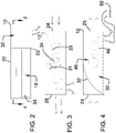
- FIG. 2 is a front view of an embodiment of the disclosure.
- FIG. 3 is a right side phantom view of an embodiment of the disclosure.
- FIG. 4 is a left side phantom view of an embodiment of the disclosure.
- FIG. 5 is a cross sectional view taken along line 5 - 5 of FIG. 2 of an embodiment of the disclosure.
- FIG. 6 is a perspective view of a turbine and drive gears of an embodiment of the disclosure.
- FIG. 7 is a back perspective view of an embodiment of the disclosure.
- FIG. 8 is a left side phantom view of an alternative embodiment of the disclosure.
- FIG. 9 is a right view of an alternative embodiment of the disclosure.
- FIG. 10 is a front view of an embodiment of the disclosure.
- FIG. 11 is a top phantom view of an alternative embodiment of the disclosure.
- FIG. 12 is a perspective in-use view of an embodiment of the disclosure.
- FIGS. 1 through 12 With reference now to the drawings, and in particular to FIGS. 1 through 12 thereof, a new generator device embodying the principles and concepts of an embodiment of the disclosure and generally designated by the reference numeral 10 will be described.
- the wind generator assembly 10 generally comprises a housing 12 that is mounted on a roof 14 of a vehicle 16 .
- the housing 12 has a wind passage 18 extending therethrough, and wind passes through the wind passage 18 when the vehicle 16 is driven.
- the vehicle 16 may be an electric passenger vehicle or a hybrid passenger vehicle that is driven on public roadways.
- the housing 12 has a bottom wall 20 , a top wall 22 , a front wall 24 and a back wall 26 , and the wind passage 18 extends through each of the front wall 24 and the back wall 26 .
- a divider 28 is positioned within the housing 12 and the divider 28 extends between the front wall 24 and the back wall 26 to define a generator space 30 in the housing 12 .
- the generator space 30 is positioned adjacent to the wind passage 18 .
- the housing 12 may be a unitary structure of the vehicle 16 or the housing 12 may be retrofitted onto the vehicle 16 .
- the top wall 22 has a curved portion 32 curving downwardly toward the bottom wall 20 .
- the curved portion 32 is aligned with the generator space 30 .
- the curved portion 32 is positioned on the front wall 24 to reduce drag with respect to air passing over the curved portion 32 when the vehicle 16 is driven.
- the bottom wall 20 is coupled to the roof 14 of the vehicle 16 having the front wall 24 being directed forwardly on the vehicle 16 .
- the wind passage 18 has an upper bounding surface 29 and the upper bounding surface 29 may slope downwardly between each of the front wall 24 and the back wall 26 of the housing 12 . Additionally, the upper bounding surface 29 may have a recess 31 that is centrally positioned in the wind passage 18 .
- a turbine 34 is rotatably positioned in the housing 12 and the turbine 34 is positioned in the wind passage 18 . In this way the turbine 34 is rotated by wind passing through the wind passage 18 .
- the turbine 34 has a first end 36 and a second end 38 , and the turbine 34 is elongated between the first end 36 and the second end 38 .
- Each of the first end 36 and the second end 38 is rotatably coupled to the housing 12 having the turbine 34 extending laterally across the wind passage 18 .
- the turbine 34 has a plurality of vanes 40 thereon and each of the vanes 40 has a distal end 42 with respect to a center line 44 of the turbine 34 .
- Each of the vanes 40 is concavely arcuate between the center line 44 and the distal end 42 for capturing wind.
- the turbine 34 is oriented in the wind passage 18 such that each of the vanes 40 curves toward the front wall 24 of the housing 12 when the vanes 40 are directed downwardly during rotation of the turbine 34 . Additionally, the turbine 34 may be positioned in the recess 31 in the upper bounding surface 29 of the wind passage 18 .
- a set of drive gears 46 is provided and each of the drive gears 46 is rotatably coupled to the divider 28 .
- Each of the drive gears 46 is in mechanical communication with the turbine 34 such that the turbine 34 rotates the drive gears 46 when the turbine 34 is rotated.
- Each of the drive gears 46 is positioned in the generator space 30 . Additionally, the set of drive gears 46 may multiply the rotational speed of the turbine 34 .
- a generator 48 is mounted in the generator space 30 .
- the generator 48 is in mechanical communication with the turbine 34 such that the turbine 34 rotates the generator 48 when the turbine 34 rotates. In this way the generator 48 can produce electrical current.
- the generator 48 is electrically coupled to batteries 50 in the vehicle 16 to charge the batteries 50 .
- the generator 48 has a drive shaft 52 and the drive shaft 52 is rotatably coupled to the drive gears 46 such that the drive gears 46 rotate the drive shaft 52 when the turbine 34 rotates.
- the generator 48 may be a electric generator similar to generators used in existing hybrid vehicles.
- the housing 12 has a first lateral wall 56 and the top wall 22 of the housing 12 has a pivot point 58 .
- the pivot point 58 is pivotally coupled to a bottom side 60 of the vehicle 16 .
- a wheel 62 is rotatably coupled to the first lateral wall 56 of the housing 12 such that the wheel 62 rolls along the road 61 .
- the pivot point 58 facilitates the wheel 62 to travel over uneven surfaces when the vehicle 16 is moving.
- the wheel 62 includes an axle 64 extending through the first lateral wall 56 of the housing 12 .
- the axle 64 engages the drive gears 46 such that the wheel 62 rotates the drive gears 46 when the wheel 62 is rotated for charging the batteries 50 of the vehicle 16 .
- the turbine 34 is rotated by wind when the vehicle 16 is driven.
- the generator 48 is turned to produce electrical current with wind energy.
- the generator 48 charges the batteries 50 in the vehicle 16 when the vehicle 16 is driven. In this way the generator 48 enhances the range of electric vehicles or hybrid vehicles. Additionally, the generator 48 is in electrical communication with battery charging circuitry in the vehicle 16 for controlling the output of the generator 48 .
Landscapes
- Engineering & Computer Science (AREA)
- Life Sciences & Earth Sciences (AREA)
- Sustainable Development (AREA)
- Sustainable Energy (AREA)
- Mechanical Engineering (AREA)
- Power Engineering (AREA)
- Chemical & Material Sciences (AREA)
- Combustion & Propulsion (AREA)
- General Engineering & Computer Science (AREA)
- Transportation (AREA)
- Electric Propulsion And Braking For Vehicles (AREA)
- Wind Motors (AREA)
Abstract
Description
Claims (6)
Priority Applications (1)
| Application Number | Priority Date | Filing Date | Title |
|---|---|---|---|
| US16/527,265 US11480154B2 (en) | 2019-07-31 | 2019-07-31 | Vehicle roof-mounted wind generator assembly having a curved front housing portion and a horizontal-axis wind turbine |
Applications Claiming Priority (1)
| Application Number | Priority Date | Filing Date | Title |
|---|---|---|---|
| US16/527,265 US11480154B2 (en) | 2019-07-31 | 2019-07-31 | Vehicle roof-mounted wind generator assembly having a curved front housing portion and a horizontal-axis wind turbine |
Publications (2)
| Publication Number | Publication Date |
|---|---|
| US20210033070A1 US20210033070A1 (en) | 2021-02-04 |
| US11480154B2 true US11480154B2 (en) | 2022-10-25 |
Family
ID=74259096
Family Applications (1)
| Application Number | Title | Priority Date | Filing Date |
|---|---|---|---|
| US16/527,265 Active 2040-10-28 US11480154B2 (en) | 2019-07-31 | 2019-07-31 | Vehicle roof-mounted wind generator assembly having a curved front housing portion and a horizontal-axis wind turbine |
Country Status (1)
| Country | Link |
|---|---|
| US (1) | US11480154B2 (en) |
Families Citing this family (2)
| Publication number | Priority date | Publication date | Assignee | Title |
|---|---|---|---|---|
| US12014096B1 (en) | 2023-09-14 | 2024-06-18 | Bank Of America Corporation | System and method for remote authentication based on computer-vision technologies |
| PL131678U1 (en) * | 2023-09-22 | 2025-03-24 | Instytut Maszyn Przepływowych Im. Roberta Szewalskiego Polskiej Akademii Nauk | Wind turbine system for use on a transport vehicle |
Citations (14)
| Publication number | Priority date | Publication date | Assignee | Title |
|---|---|---|---|---|
| US4019828A (en) * | 1974-11-01 | 1977-04-26 | Bunzer George J | Wind driven apparatus |
| US4179007A (en) * | 1978-06-01 | 1979-12-18 | Howe Robert R | Wind operated power generating apparatus |
| USD374656S (en) | 1994-08-31 | 1996-10-15 | Richardson Carl D | Car top wind generator |
| US20040084908A1 (en) | 2002-11-05 | 2004-05-06 | Vu Thomas H. | Wind energy capturing device for moving vehicles |
| US20110031043A1 (en) * | 2009-08-06 | 2011-02-10 | Sara Armani | Self-charging electrical car with wind energy recovery system |
| US20110248666A1 (en) | 2010-01-20 | 2011-10-13 | Leigh Lorenson | Turbine-powered electric vehicle |
| US20110260470A1 (en) * | 2010-04-23 | 2011-10-27 | William Ahmadi | Tribrid electric transportation system |
| US8067846B2 (en) | 2008-09-10 | 2011-11-29 | Timothy W Kiler | Automotive wind powered generator |
| US8169182B1 (en) | 2008-06-02 | 2012-05-01 | Denny Kimble | Charging system for an electric vehicle |
| US8371401B1 (en) | 2010-11-01 | 2013-02-12 | Vito J. Illustrato | Electric power hybrid propulsion generation system for a motor vehicle |
| US20130127393A1 (en) * | 2011-11-18 | 2013-05-23 | Rafael Garcia | Wind Operated Electricity Generating System |
| US20160153308A1 (en) * | 2013-07-31 | 2016-06-02 | Claudio MUNERATO | Auxiliary generator of electrical energy |
| US9428061B1 (en) | 2012-05-14 | 2016-08-30 | Peter W. Ripley | Wind turbine for electric car |
| US9446670B1 (en) | 2015-02-05 | 2016-09-20 | Jeffrey McCorkindale | Energy generating system |
-
2019
- 2019-07-31 US US16/527,265 patent/US11480154B2/en active Active
Patent Citations (15)
| Publication number | Priority date | Publication date | Assignee | Title |
|---|---|---|---|---|
| US4019828A (en) * | 1974-11-01 | 1977-04-26 | Bunzer George J | Wind driven apparatus |
| US4179007A (en) * | 1978-06-01 | 1979-12-18 | Howe Robert R | Wind operated power generating apparatus |
| USD374656S (en) | 1994-08-31 | 1996-10-15 | Richardson Carl D | Car top wind generator |
| US20040084908A1 (en) | 2002-11-05 | 2004-05-06 | Vu Thomas H. | Wind energy capturing device for moving vehicles |
| US8169182B1 (en) | 2008-06-02 | 2012-05-01 | Denny Kimble | Charging system for an electric vehicle |
| US8067846B2 (en) | 2008-09-10 | 2011-11-29 | Timothy W Kiler | Automotive wind powered generator |
| US20110031043A1 (en) * | 2009-08-06 | 2011-02-10 | Sara Armani | Self-charging electrical car with wind energy recovery system |
| US20110248666A1 (en) | 2010-01-20 | 2011-10-13 | Leigh Lorenson | Turbine-powered electric vehicle |
| US20110260470A1 (en) * | 2010-04-23 | 2011-10-27 | William Ahmadi | Tribrid electric transportation system |
| US8371401B1 (en) | 2010-11-01 | 2013-02-12 | Vito J. Illustrato | Electric power hybrid propulsion generation system for a motor vehicle |
| US20130127393A1 (en) * | 2011-11-18 | 2013-05-23 | Rafael Garcia | Wind Operated Electricity Generating System |
| US9428061B1 (en) | 2012-05-14 | 2016-08-30 | Peter W. Ripley | Wind turbine for electric car |
| US20160153308A1 (en) * | 2013-07-31 | 2016-06-02 | Claudio MUNERATO | Auxiliary generator of electrical energy |
| US10138753B2 (en) * | 2013-07-31 | 2018-11-27 | Claudio MUNERATO | Auxiliary fluid driven electric generator |
| US9446670B1 (en) | 2015-02-05 | 2016-09-20 | Jeffrey McCorkindale | Energy generating system |
Also Published As
| Publication number | Publication date |
|---|---|
| US20210033070A1 (en) | 2021-02-04 |
Similar Documents
| Publication | Publication Date | Title |
|---|---|---|
| US4314160A (en) | Wind turbine generator for electrical powered vehicles | |
| US6882059B1 (en) | Vehical wind operated generator | |
| US6897575B1 (en) | Portable wind power apparatus for electric vehicles | |
| US5986429A (en) | Battery charging system for electric vehicles | |
| US8710691B2 (en) | Wind driven generator for vehicles | |
| TW200831318A (en) | Improved apparatus of wind power for automobiles | |
| US20060213697A1 (en) | Power system for electric and hybrid vehicles | |
| US20120085587A1 (en) | Wind Power for Electric Cars | |
| US11480154B2 (en) | Vehicle roof-mounted wind generator assembly having a curved front housing portion and a horizontal-axis wind turbine | |
| US9770990B2 (en) | Energy generating and storage system for electric vehicle | |
| US20160195066A1 (en) | Vehicular wind power generator | |
| WO2008140470A1 (en) | Wind energy extender | |
| US20120187685A1 (en) | Air driven electric generator for charging a battery | |
| WO2003081035A1 (en) | Wind power generator for vehicle | |
| CN101592119A (en) | The wind-driven electric generator for car that utilizes carbon fiber composite to produce | |
| GB2292718A (en) | Vehicle with wind-driven turbine to generate electric power | |
| CN101850717A (en) | Vehicle-mounted wind-driven generator system | |
| CN201573537U (en) | Vehicle-mounted wind-driven generator system | |
| CN206171210U (en) | Wind -power and solar electric vehicles | |
| US20200101857A1 (en) | Wind turbine for electric vehicles | |
| Goel et al. | Solar hybrid electric vehicle—A green vehicle for future impulse | |
| CN211830313U (en) | Movable wind power charging device | |
| KR102152650B1 (en) | Electric vehicle having self-generation function | |
| CN201941604U (en) | Automobile wind power device | |
| US20220212557A1 (en) | Charging system for electric vehicles |
Legal Events
| Date | Code | Title | Description |
|---|---|---|---|
| FEPP | Fee payment procedure |
Free format text: ENTITY STATUS SET TO UNDISCOUNTED (ORIGINAL EVENT CODE: BIG.); ENTITY STATUS OF PATENT OWNER: MICROENTITY |
|
| FEPP | Fee payment procedure |
Free format text: ENTITY STATUS SET TO SMALL (ORIGINAL EVENT CODE: SMAL); ENTITY STATUS OF PATENT OWNER: MICROENTITY Free format text: ENTITY STATUS SET TO MICRO (ORIGINAL EVENT CODE: MICR); ENTITY STATUS OF PATENT OWNER: MICROENTITY |
|
| STPP | Information on status: patent application and granting procedure in general |
Free format text: DOCKETED NEW CASE - READY FOR EXAMINATION |
|
| STPP | Information on status: patent application and granting procedure in general |
Free format text: NON FINAL ACTION MAILED |
|
| STPP | Information on status: patent application and granting procedure in general |
Free format text: RESPONSE TO NON-FINAL OFFICE ACTION ENTERED AND FORWARDED TO EXAMINER |
|
| STPP | Information on status: patent application and granting procedure in general |
Free format text: NOTICE OF ALLOWANCE MAILED -- APPLICATION RECEIVED IN OFFICE OF PUBLICATIONS |
|
| STPP | Information on status: patent application and granting procedure in general |
Free format text: PUBLICATIONS -- ISSUE FEE PAYMENT VERIFIED |
|
| STCF | Information on status: patent grant |
Free format text: PATENTED CASE |