US11470949B2 - Binocular harness system - Google Patents
Binocular harness system Download PDFInfo
- Publication number
- US11470949B2 US11470949B2 US17/239,633 US202117239633A US11470949B2 US 11470949 B2 US11470949 B2 US 11470949B2 US 202117239633 A US202117239633 A US 202117239633A US 11470949 B2 US11470949 B2 US 11470949B2
- Authority
- US
- United States
- Prior art keywords
- main body
- binocular
- harness system
- panel
- situated
- Prior art date
- Legal status (The legal status is an assumption and is not a legal conclusion. Google has not performed a legal analysis and makes no representation as to the accuracy of the status listed.)
- Active, expires
Links
Images


Classifications
-
- A—HUMAN NECESSITIES
- A45—HAND OR TRAVELLING ARTICLES
- A45F—TRAVELLING OR CAMP EQUIPMENT: SACKS OR PACKS CARRIED ON THE BODY
- A45F3/00—Travelling or camp articles; Sacks or packs carried on the body
- A45F3/14—Carrying-straps; Pack-carrying harnesses
-
- A—HUMAN NECESSITIES
- A45—HAND OR TRAVELLING ARTICLES
- A45C—PURSES; LUGGAGE; HAND CARRIED BAGS
- A45C11/00—Receptacles for purposes not provided for in groups A45C1/00-A45C9/00
- A45C11/08—Cases for telescopes or binoculars
-
- A—HUMAN NECESSITIES
- A45—HAND OR TRAVELLING ARTICLES
- A45F—TRAVELLING OR CAMP EQUIPMENT: SACKS OR PACKS CARRIED ON THE BODY
- A45F3/00—Travelling or camp articles; Sacks or packs carried on the body
- A45F3/04—Sacks or packs carried on the body by means of two straps passing over the two shoulders
- A45F3/047—Sacks or packs carried on the body by means of two straps passing over the two shoulders with adjustable fastenings for the shoulder straps or waist belts
-
- A—HUMAN NECESSITIES
- A45—HAND OR TRAVELLING ARTICLES
- A45F—TRAVELLING OR CAMP EQUIPMENT: SACKS OR PACKS CARRIED ON THE BODY
- A45F3/00—Travelling or camp articles; Sacks or packs carried on the body
- A45F3/14—Carrying-straps; Pack-carrying harnesses
- A45F2003/146—Pack-carrying harnesses
-
- A45F2200/05—
Definitions
- the present invention relates generally to the field of outdoor recreational gear, and more particularly, to an adjustable harness system for carrying binoculars in the field.
- U.S. Pat. No. 3,782,614 (Campisi, 1974) discloses a binocular pocket that is adapted to be attached to an upper torso garment.
- the pocket comprises a body member and a flap member that is detachably attached to the body member.
- the flap member has an opening intermediate to the sides of the flap member to permit the binocular straps to pass through and rest around the neck of the wearer of the garment.
- U.S. Pat. No. 6,095,328 (Smithbaker, III el at, 2000) provides a carrying case for binoculars in which a tubular-shaped main body formed of a stretchable and resilient material is undersized in relation to the binoculars.
- the main body has openings on either end for exposing the binocular lenses and an aperture for exposing a focus adjustment mechanism during use.
- Each of the openings and aperture has a removable closure.
- U.S. Pat. No. 6,926,184 discloses a harness system for holding an article such as binoculars.
- the system comprises a pair of shoulder straps, a pair of underarm straps, and a case disposed on the front of the wearer.
- the case has a cover with a substantially rigid lip hinged to the top edge that pivots into the space between the article and the body of the user.
- the cover incorporates a face sheet that interconnects the spaced apart sides of the cover to which the underarm straps are connected.
- the face sheet is curved to form a bottom edge that is situated beneath the binoculars and a top edge that extends above the upper end of the binoculars.
- U.S. Pat. No. 9,872,553 provides a support system and carrying case for binoculars.
- the system includes a neck strap and carrying case with a top opening.
- the carrying case is supported by a pair of elastomeric case support straps, each of which is coupled to an intermediate portion of the neck strap.
- a strap assembly is coupled to the lower portion of the case and attachable to a belt or garment of the user.
- the invention further comprises a case lid with a closure fastener that is releaseable upon downward movement of the case.
- U.S. Pat. No. D271540 depicts a binocular case design comprised of a relatively hard case with top and rear covers that are hingedly removable. This design does not incorporate a harness system.
- U.S. Pat. No. D601341 (Arman, 2009) illustrates a binocular case design comprised of three parts, the first of which fits around a center portion of the binoculars, and the second and third of which form separate covers for each end of the binoculars. The second and third parts of the cover are joined to each other and to the second part so that they can be pulled off the ends of the binoculars without falling off.
- This design does not incorporate a harness system.
- U.S. Pat. No. D853111 shows a binocular case design featuring a purse-like compartment on the front of the wearer and an elongated, zippered pocket on the back side of the wearer.
- the purse-like compartment includes outer side pockets and horizontal rows of nylon webbing configured to facilitate the attachment of implements.
- This design incorporates a harness system.
- the present invention is a binocular harness system comprising: a pair of shoulder straps; a pair of upper torso straps; and a carrying pouch; wherein the carrying pouch comprises a main body and a removable hood; wherein the main body comprises a front side, a back side, two side walls that join the front side to the back side, and a bottom panel; wherein the front side of the main body comprises a panel of loop fastener that extends laterally across a width of the front side; wherein the hood comprises a front panel, a secondary panel that is configured to form a back and two sides of the hood, and an elongated pocket that extends along a rear edge and at least a portion of each side edge of the secondary panel; wherein the elongated pocket contains a rod; and wherein an elastomeric cord passes through a central bore in the rod, through side portions of the elongated pocket, through loops situated on either side of the back side of the main body, and through conduits made of nylon webbing situated
- the present invention further comprises a fastener loop made of nylon webbing situated directly underneath the loop fastener panel on a right side of the front side of the main body and a fastener loop made of nylon webbing situated directly underneath the loop fastener panel on a left side of the front side of the main body.
- the bottom panel of the main body comprises a loop fastener made of nylon webbing situated on a right side of the bottom panel and a fastener loop made of nylon webbing situated on a left side of the bottom panel.
- the present invention preferably further comprises a pull tab that is attached to an outside center of the elongated pocket.
- the present invention preferably further comprises a side pocket on an outside of each of the two side walls and an elastomeric member that extends across a top of each side pocket.
- each upper torso strap is attached to one side of the back side of the main body with a buckle, one part of which passes through the loop on a right or left side of the back side of the main body.
- the shoulder straps are joined to the upper torso straps by a back member.
- the shoulder straps are preferably adjustable in length via ratchet buckles located on distal ends of the shoulder straps.
- the distal ends of the shoulder straps are attached to a top edge of a back plate, and a back face of the back plate is covered with a panel of loop fastener material.
- the elastomeric cord makes a full loop that terminates at a cord fastener that joins two ends of the elastomeric cord together and is situated between the conduits.
- the present invention preferably comprises a foam pad that is situated between the back side of the main body and a mesh pocket.
- the present invention preferably comprises a foam pad on an inside of the front side of the main body.
- an inside surface of the back side of the main body is covered with a hook fastener material.
- a strip of hook fastener material extends across an inside front end of the hood.
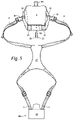
- FIG. 1 is a front view of the invention shown worn by a person with the hood and back plate in a lowest position.
- FIG. 2 is a front view of the invention shown worn by a person with the hood and back late in a highest position.
- FIG. 3 is a side view of the invention shown with the hood in a closed position prior to opening.
- FIG. 4 is a side view of the invention shown with the hood in an open position.
- FIG. 5 is a front disassembled view of the invention shown with the back plate removed from the carrying pouch.
- FIG. 6 is a rear disassembled view of the invention shown with the back plate removed from the carrying pouch.
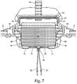
- FIG. 7 is a rear view of the invention shown with a cutaway view of the rear bottom edge of the hood.
- FIG. 8 is a front view of the invention shown with the hood in an open position prior to insertion of the back plate.
- FIG. 9 is a front perspective view of the present invention illustrating the insertion and adjustment of the back plate inside the carrying pouch.
- FIG. 10 is a front perspective view of the present invention shown with the hood in an open position.
- FIG. 11 is a front perspective view of the present Invention shown with the hood in an open position and a pair of binoculars situated in the carrying pouch.
- FIG. 12 is a front view of the present invention shown with the hood pulled back and the front side of the main body fully exposed.
- FIG. 13 is a side section view of the present invention showing the floor and foam padding on the inside of the main body.
- FIG. 14 is a bottom view of the present invention.
- FIG. 15 is a perspective view of the present invention shown fully assembled with the hood pulled forward and the binoculars exposed.
- FIG. 1 is a front view of the invention shown worn by a person with the hood and back plate in a lowest position.
- the present invention comprises a pair of shoulder straps 1 , a pair of upper torso straps 2 , and a carrying pouch 3 .
- the carrying pouch 3 comprises a main body 4 and a removable hood 5 .
- the main body 4 comprises a front side 6 , a back side 7 , and two side walls 8 that join the front side to the back side.
- the main body 4 further comprises a floor 9 with foam padding 10 to protect the article contained within the main body.
- the foam padding 10 may be removably attached to the floor 9 with hook-and-loop fastener (see FIG. 13 ).
- FIG. 2 is a front view of the invention shown worn by a person with the hood and back plate in a highest position.
- the front side 6 of the main body comprises a panel of loop fastener 11 that extends laterally across the full width of the front side 6 and downwardly over at least half of the height of the front side 6 (see FIG. 12 ).
- fastener loops 12 Situated directly underneath the loop fastener panel 11 on the far right and left sides of the front side 6 are fastener loops 12 made of nylon webbing. Similar fastener loops 12 are located on either side of the bottom panel 13 of the carrying pouch 3 (see FIG. 14 ).
- the fastener loops 12 facilitate the attachment of various tools and implements.
- FIG. 3 is a side view of the invention shown with the hood in a closed position prior to opening.
- the hood 5 comprises a front panel 13 , a secondary panel 14 that forms the back and sides of the hood 5 , and an elongated pocket 15 that extends along the entire rear edge and at least a portion of each of the side edges of the secondary panel 14 .
- the front panel 13 and the secondary panel 14 may be formed from the same piece of material or separate pieces of material. They may also each be formed from more than one piece of material.
- a pull tab 16 that is preferably comprised of nylon webbing with an internal rigid (plastic) plate for ease of grasp is attached to the outside of the center of the elongated pocket 15 .
- Side pockets 17 are provided on the outside of each of the side walls 8 , and an elastomeric member 18 extends across the top of each side pocket 17 to prevent items within the side pocket from falling out.
- Each upper torso strap 2 is attached to one side (right and left) of the back side 7 of the main body 4 with a buckle 19 , one part of which passes through a loop 20 formed of nylon webbing.
- the upper torso straps 2 can be decoupled from the loops 20 by unfastening the buckles 19 .
- an elastomeric cord 21 passes through a rod 22 in the elongated pocket 15 , through the side portions 23 of the elongated pocket 15 , through the loops 20 and then through a conduit 24 formed with the same nylon webbing that forms the fastener loops 12 on the bottom panel 13 of the carrying pouch 3 (see FIG. 14 ).
- the conduits 24 are situated between the fastener loops 12 on the bottom panel 13 and the mesh pocket 25 that covers the entire outer surface of the back side 7 of the main body 4 (see FIG. 7 ).
- FIG. 4 is a side view of the invention shown with the hood in an open position.
- the present invention is specifically designed to allow the binoculars to be accessed quickly and quietly in those situations (such as hunting) in which stealth is important. For this reason, the present invention does not require the use of magnets, snaps, buckles or other types of fasteners that make noise in order to access the binoculars (buckles are used only to adjust the harness system on the wearer prior to heading into the field).
- FIG. 5 is a front disassembled view of the invention shown with the back plate removed from the carrying pouch.
- the upper torso straps 2 are adjustable in length via the buckles 19 .
- the shoulder straps 1 are joined to the upper torso straps 2 by a back member 27 , preferably made of the same material of which the hood 5 and carrying pouch 3 are made. In a preferred embodiment, this material is waterproof, windproof and breathable material such as HYDRASHIELDTM canvas made by Kodiak Canvas of Layton, Utah.
- the present invention is designed to be worn underneath a backpack, in which case the back member 27 would lie between the backpack and the wearer.
- the length of the shoulder straps 1 is also adjustable via ratchet buckles 28 located on the distal ends (that is, the end farthest from the back member 27 ) of the Shoulder straps 1 .
- the distal ends of the shoulder straps 1 are attached to the top edge of the back plate 26 on either side of the back plate extension 29 .
- the back plate 26 and back plate extension 29 are comprised of a relative rigid material (such as plastic) and overlaid with the same canvas material as the hood 5 and carrying case 3 .
- the back plate extension 29 protrudes upwardly from the center of the top edge of the back plate 26 .
- the front face 30 of the back plate 26 is comprised of canvas material, whereas the entire back face 31 of the back plate 26 is covered with a panel of loop fastener material 32 (see FIG. 0 ).
- FIG. 6 is a rear disassembled view of the invention shown with the back plate removed from the carrying pouch.
- the elastomeric cord 21 makes a full loop that terminates at a cord fastener 33 that joins the two ends of the elastomeric cord 21 together and is situated in between the conduits 24 on the bottom panel 13 , directly underneath the mesh pocket 25 .
- the tension on the elastomeric cord 21 may be adjusted via the cord fastener 33 in order to accommodate smaller or larger sizes of binoculars.
- the hood 5 is in a closed position over the binoculars, the elastomeric cord 21 maintains downward pressure on the hood 5 , thereby keeping the binoculars secure and preventing them from shifting inside of the carrying pouch 3 .
- FIG. 7 is a rear view of the invention shown with a cutaway view of the rear bottom edge of the hood.
- a rod 22 is situated within that portion of the elongated pocket 15 that extends across the rear edge of the hood 5 .
- the elongated rod 22 comprises a central bore through which the elastomeric cord 21 passes.
- This figure clearly shows the loop made by the elastomeric cord 21 , which supplies the tension that holds the hood 5 over the top of the binoculars.
- a foam pad preferably lies between the mesh pocket 25 and the back side 7 of the main body 4 .
- This foam pad preferably covers the entire back surface of the back side 7 of the main body 4 in order to provide cushioning for the binoculars.
- a similar foam pad (not shown) is also situated on the inside of the front side 6 of the main body 4 . Please note that the shoulder straps have been omitted from this figure for clarity.
- FIG. 8 is a front view of the invention shown with the hood in an open position prior to insertion of the back plate.
- the entire inside surface of the back side 7 of the main body 4 is covered with a hook fastener material 34 .
- the purpose of the adjustability of the height of the back plate 26 is to allow the carrying pouch 3 to accommodate smaller or larger sizes of binoculars.
- the position of the hood 5 relative to the front side 6 of the main body 4 may also be adjusted.
- a strip of hook fastener material 35 extends across the inside front end of the hood 5 .
- This strip of hook fastener material 35 can be positioned on the loop fastener panel 11 , as needed, to accommodate smaller or larger sizes of binoculars.
- FIG. 9 is a front perspective view of the present invention illustrating the insertion and adjustment of the back plate inside the carrying pouch. As shown in this figure, the internal compartment of the carrying pouch 3 is exposed without the need to un-do any hook-and-loop fasteners (which make noise) or unclip any buckles.
- the hook-and-loop fasteners are used only to adjust the size of the invention to fit a particular pair of binoculars before going out into the field.
- FIG. 10 is a front perspective view of the present invention shown with the hood in an open position
- FIG. 11 is a front perspective view of the present invention shown with the hood in an open position and a pair of binoculars situated in the carrying pouch.
- the back plate 26 is at its lowest position within the carrying pouch 3 . Ideally, the back plate 26 is situated so that the top of the back plate 26 is approximately 0.75 inches below eye cup height.
Landscapes
- Portable Outdoor Equipment (AREA)
Abstract
Description
-
- 1 Shoulder strap
- 2 Upper torso strap
- 3 Carrying pouch
- 4 Main body (of carrying pouch)
- 5 Removable hood
- 6 Front side (of main body)
- 7 Back side (of main body)
- 8 Side wall (of main body)
- 9 Floor (of main body)
- 10 Foam padding
- 11 Loop fastener panel
- 12 Fastener loop
- 13 Front panel
- 14 Secondary panel
- 15 Elongated pocket
- 16 Pull tab
- 17 Side pocket
- 18 Elastomeric member
- 19 Buckle
- 20 Loop
- 21 Elastomeric cord
- 22 Rod
- 23 Side portion (of elongated pocket)
- 24 Conduit
- 25 Mesh pocket
- 26 Back plate
- 27 Back member
- 28 Ratchet buckle
- 29 Back plate extension
- 30 Front face (of back plate)
- 31 Back face (of back plate)
- 32 Loop fastener material
- 33 Cord fastener
- 34 Hook fastener material
- 35 Strip of hook fastener material
Claims (16)
Priority Applications (2)
| Application Number | Priority Date | Filing Date | Title |
|---|---|---|---|
| US17/239,633 US11470949B2 (en) | 2020-05-07 | 2021-04-25 | Binocular harness system |
| US17/967,325 US11992112B2 (en) | 2020-05-07 | 2022-10-17 | Binocular harness system |
Applications Claiming Priority (2)
| Application Number | Priority Date | Filing Date | Title |
|---|---|---|---|
| US202063021199P | 2020-05-07 | 2020-05-07 | |
| US17/239,633 US11470949B2 (en) | 2020-05-07 | 2021-04-25 | Binocular harness system |
Related Child Applications (1)
| Application Number | Title | Priority Date | Filing Date |
|---|---|---|---|
| US17/967,325 Continuation US11992112B2 (en) | 2020-05-07 | 2022-10-17 | Binocular harness system |
Publications (2)
| Publication Number | Publication Date |
|---|---|
| US20210345759A1 US20210345759A1 (en) | 2021-11-11 |
| US11470949B2 true US11470949B2 (en) | 2022-10-18 |
Family
ID=78411790
Family Applications (2)
| Application Number | Title | Priority Date | Filing Date |
|---|---|---|---|
| US17/239,633 Active 2041-04-25 US11470949B2 (en) | 2020-05-07 | 2021-04-25 | Binocular harness system |
| US17/967,325 Active US11992112B2 (en) | 2020-05-07 | 2022-10-17 | Binocular harness system |
Family Applications After (1)
| Application Number | Title | Priority Date | Filing Date |
|---|---|---|---|
| US17/967,325 Active US11992112B2 (en) | 2020-05-07 | 2022-10-17 | Binocular harness system |
Country Status (1)
| Country | Link |
|---|---|
| US (2) | US11470949B2 (en) |
Cited By (3)
| Publication number | Priority date | Publication date | Assignee | Title |
|---|---|---|---|---|
| US20220211153A1 (en) * | 2018-11-21 | 2022-07-07 | Sheltered Wings, Inc. D/B/A Vortex Optics | Optical instrument case with low profile lid and harness for the same |
| US20230032543A1 (en) * | 2020-05-07 | 2023-02-02 | Stone Glacier, Inc. | Binocular harness system |
| US12269431B1 (en) * | 2024-08-29 | 2025-04-08 | William Marek Goluch | Apparatus for receiving and storing a binocular |
Families Citing this family (1)
| Publication number | Priority date | Publication date | Assignee | Title |
|---|---|---|---|---|
| US12336620B2 (en) * | 2022-06-14 | 2025-06-24 | Eberlestock Usa Llc | Accessory attachment arrangement for a wearable pack |
Citations (16)
| Publication number | Priority date | Publication date | Assignee | Title |
|---|---|---|---|---|
| US3782614A (en) * | 1972-05-01 | 1974-01-01 | J Campisi | Binocular pocket |
| USD271540S (en) | 1981-11-09 | 1983-11-29 | Williams Brandt G | Binocular case |
| US5016797A (en) * | 1988-04-14 | 1991-05-21 | Darrel Rowledge | Article carrier |
| US6095328A (en) | 1999-01-14 | 2000-08-01 | The Brunton Company | Carrying case for binoculars |
| US20040140335A1 (en) | 2003-01-21 | 2004-07-22 | Dennis Hancock | Suspended article cover hold down system |
| US7036943B1 (en) * | 2004-12-14 | 2006-05-02 | Edwin F. Brewer | Binocular cover |
| US7059503B2 (en) * | 2001-08-09 | 2006-06-13 | Andersen M Dan | Device for restraining and protecting neckstrap-supported user equipment |
| US20060151563A1 (en) * | 2005-01-07 | 2006-07-13 | Darrell Bussard | Wearable device-securing system |
| USD601341S1 (en) | 2008-11-03 | 2009-10-06 | Russ Arman | Binocular case |
| US8720681B1 (en) * | 2013-04-08 | 2014-05-13 | Jeffrey D. Hancock | Quiet opening and closing binocular pouch |
| DE102011017410A1 (en) * | 2011-04-15 | 2014-05-22 | Gisela Krumbiegel | Bag i.e. handbag, for carrying object i.e. home key, has bag main portion detachably attached to rotated flap, where flap at main portion is exchanged by another flap and provided with loops, which are connected with caps by bar |
| US9210978B1 (en) * | 2011-07-12 | 2015-12-15 | Fl Archery Holdings Llc | Equipment carrier with extensible tether |
| US9872553B1 (en) | 2016-08-01 | 2018-01-23 | Dale L. Erlandson | Support system and carrying case for optical instrument |
| USD853111S1 (en) | 2017-10-25 | 2019-07-09 | Nikon Inc. | Binocular case |
| US20210015228A1 (en) * | 2019-07-15 | 2021-01-21 | Kuiu, Llc | Reconfigurable cases for portable hand-held devices and methods |
| US11284691B2 (en) * | 2018-11-21 | 2022-03-29 | Sheltered Wings, Inc. | Optical instrument case with low profile lid and harness for the same |
Family Cites Families (6)
| Publication number | Priority date | Publication date | Assignee | Title |
|---|---|---|---|---|
| US5172838A (en) * | 1991-05-24 | 1992-12-22 | Photoflex, Inc. | Chest pouch camera carrier |
| US20080061099A1 (en) * | 2006-09-11 | 2008-03-13 | John Tilby | Range finder carrier system |
| AT9558U1 (en) | 2006-09-15 | 2007-12-15 | Diendorfer Werbe Gmbh | BAG WITH REPLACEABLE FLAP |
| US9394080B2 (en) * | 2013-03-14 | 2016-07-19 | Tyr Tactical, Llc | Adjustable ammunition magazine pouch |
| WO2019183256A1 (en) * | 2018-03-20 | 2019-09-26 | UVu, LLC | Pack assembly for a mobile device |
| US11470949B2 (en) * | 2020-05-07 | 2022-10-18 | Stone Glacier, Inc. | Binocular harness system |
-
2021
- 2021-04-25 US US17/239,633 patent/US11470949B2/en active Active
-
2022
- 2022-10-17 US US17/967,325 patent/US11992112B2/en active Active
Patent Citations (17)
| Publication number | Priority date | Publication date | Assignee | Title |
|---|---|---|---|---|
| US3782614A (en) * | 1972-05-01 | 1974-01-01 | J Campisi | Binocular pocket |
| USD271540S (en) | 1981-11-09 | 1983-11-29 | Williams Brandt G | Binocular case |
| US5016797A (en) * | 1988-04-14 | 1991-05-21 | Darrel Rowledge | Article carrier |
| US6095328A (en) | 1999-01-14 | 2000-08-01 | The Brunton Company | Carrying case for binoculars |
| US7059503B2 (en) * | 2001-08-09 | 2006-06-13 | Andersen M Dan | Device for restraining and protecting neckstrap-supported user equipment |
| US20040140335A1 (en) | 2003-01-21 | 2004-07-22 | Dennis Hancock | Suspended article cover hold down system |
| US6926184B2 (en) * | 2003-01-21 | 2005-08-09 | Hhh Enterprises Llc | Suspended article cover hold down system |
| US7036943B1 (en) * | 2004-12-14 | 2006-05-02 | Edwin F. Brewer | Binocular cover |
| US20060151563A1 (en) * | 2005-01-07 | 2006-07-13 | Darrell Bussard | Wearable device-securing system |
| USD601341S1 (en) | 2008-11-03 | 2009-10-06 | Russ Arman | Binocular case |
| DE102011017410A1 (en) * | 2011-04-15 | 2014-05-22 | Gisela Krumbiegel | Bag i.e. handbag, for carrying object i.e. home key, has bag main portion detachably attached to rotated flap, where flap at main portion is exchanged by another flap and provided with loops, which are connected with caps by bar |
| US9210978B1 (en) * | 2011-07-12 | 2015-12-15 | Fl Archery Holdings Llc | Equipment carrier with extensible tether |
| US8720681B1 (en) * | 2013-04-08 | 2014-05-13 | Jeffrey D. Hancock | Quiet opening and closing binocular pouch |
| US9872553B1 (en) | 2016-08-01 | 2018-01-23 | Dale L. Erlandson | Support system and carrying case for optical instrument |
| USD853111S1 (en) | 2017-10-25 | 2019-07-09 | Nikon Inc. | Binocular case |
| US11284691B2 (en) * | 2018-11-21 | 2022-03-29 | Sheltered Wings, Inc. | Optical instrument case with low profile lid and harness for the same |
| US20210015228A1 (en) * | 2019-07-15 | 2021-01-21 | Kuiu, Llc | Reconfigurable cases for portable hand-held devices and methods |
Cited By (5)
| Publication number | Priority date | Publication date | Assignee | Title |
|---|---|---|---|---|
| US20220211153A1 (en) * | 2018-11-21 | 2022-07-07 | Sheltered Wings, Inc. D/B/A Vortex Optics | Optical instrument case with low profile lid and harness for the same |
| US12070110B2 (en) * | 2018-11-21 | 2024-08-27 | Sheltered Wings, Inc. | Optical instrument case with low profile lid and harness for the same |
| US20230032543A1 (en) * | 2020-05-07 | 2023-02-02 | Stone Glacier, Inc. | Binocular harness system |
| US11992112B2 (en) * | 2020-05-07 | 2024-05-28 | Stone Glacier, Inc. | Binocular harness system |
| US12269431B1 (en) * | 2024-08-29 | 2025-04-08 | William Marek Goluch | Apparatus for receiving and storing a binocular |
Also Published As
| Publication number | Publication date |
|---|---|
| US11992112B2 (en) | 2024-05-28 |
| US20230032543A1 (en) | 2023-02-02 |
| US20210345759A1 (en) | 2021-11-11 |
Similar Documents
| Publication | Publication Date | Title |
|---|---|---|
| US11470949B2 (en) | Binocular harness system | |
| US11272685B2 (en) | Pet carrying backpack | |
| US5205448A (en) | Multifunctional camera bag with waist belt support | |
| US8490844B2 (en) | Front infant carrier | |
| US6295650B1 (en) | Upland pack vest | |
| US8991671B2 (en) | Load carrier device | |
| US5669170A (en) | Hands-free sling for carrying a long gun or other elongated article | |
| EP1402799B1 (en) | Pack with front pouch and back pouch | |
| EP2387908A2 (en) | Backpack | |
| JP2026016699A (en) | Pet harness and compatible dog carrier backpack that can be held and carried by the dog | |
| US20070152007A1 (en) | Modular Pack System | |
| US20060000856A1 (en) | Hydration pack | |
| US20020124808A1 (en) | Carrier for pets | |
| US20050040199A1 (en) | Wearable device for carrying an elongated structure in a generally vertical orientation | |
| WO1994000036A1 (en) | Flipover carrying device | |
| EP3905925B1 (en) | Cinch pack | |
| US20070145091A1 (en) | Holster for packs | |
| US20070235490A1 (en) | Carrying case for a blender | |
| US10506868B2 (en) | Sporting weapon backpack | |
| US20050274767A1 (en) | Tool belt | |
| US20180118124A1 (en) | Automobile gun holster | |
| JP3246969U (en) | Shoulder bag | |
| US20260060406A1 (en) | Bag including an adjustment system | |
| GB2241880A (en) | Rucksack/bum-bag | |
| US12274375B2 (en) | Child carrier |
Legal Events
| Date | Code | Title | Description |
|---|---|---|---|
| FEPP | Fee payment procedure |
Free format text: ENTITY STATUS SET TO UNDISCOUNTED (ORIGINAL EVENT CODE: BIG.); ENTITY STATUS OF PATENT OWNER: LARGE ENTITY |
|
| FEPP | Fee payment procedure |
Free format text: ENTITY STATUS SET TO SMALL (ORIGINAL EVENT CODE: SMAL); ENTITY STATUS OF PATENT OWNER: LARGE ENTITY |
|
| AS | Assignment |
Owner name: STONE GLACIER, INC., MONTANA Free format text: ASSIGNMENT OF ASSIGNORS INTEREST;ASSIGNORS:RACICOT, KURT MICHAEL;SPOSITO, JEFFREY ROBERT;REEL/FRAME:056119/0489 Effective date: 20210503 |
|
| STPP | Information on status: patent application and granting procedure in general |
Free format text: DOCKETED NEW CASE - READY FOR EXAMINATION |
|
| STPP | Information on status: patent application and granting procedure in general |
Free format text: NOTICE OF ALLOWANCE MAILED -- APPLICATION RECEIVED IN OFFICE OF PUBLICATIONS |
|
| FEPP | Fee payment procedure |
Free format text: ENTITY STATUS SET TO UNDISCOUNTED (ORIGINAL EVENT CODE: BIG.); ENTITY STATUS OF PATENT OWNER: LARGE ENTITY |
|
| AS | Assignment |
Owner name: JPMORGAN CHASE BANK, N.A., AS THE ADMINISTRATIVE AGENT, ILLINOIS Free format text: SECURITY INTEREST;ASSIGNORS:AMMUNITION OPERATIONS LLC;BEE STINGER, LLC;BELL SPORTS, INC.;AND OTHERS;REEL/FRAME:061521/0747 Effective date: 20220805 Owner name: CAPITAL ONE, NATIONAL ASSOCIATION, AS AGENT, MARYLAND Free format text: SECURITY INTEREST;ASSIGNORS:AMMUNITION OPERATIONS LLC;BELL SPORTS, INC.;BUSHNELL HOLDINGS, INC.;AND OTHERS;REEL/FRAME:061085/0706 Effective date: 20220805 |
|
| STPP | Information on status: patent application and granting procedure in general |
Free format text: PUBLICATIONS -- ISSUE FEE PAYMENT VERIFIED |
|
| STCF | Information on status: patent grant |
Free format text: PATENTED CASE |
|
| AS | Assignment |
Owner name: SIMMS FISHING PRODUCTS LLC, MONTANA Free format text: TERMINATION AND RELEASE OF TERM LOAN INTELLECTUAL PROPERTY SECURITY AGREEMENT;ASSIGNOR:JPMORGAN CHASE BANK, N.A., AS ADMINISTRATIVE AGENT;REEL/FRAME:066959/0001 Effective date: 20240306 Owner name: FOX HEAD, INC., CALIFORNIA Free format text: TERMINATION AND RELEASE OF TERM LOAN INTELLECTUAL PROPERTY SECURITY AGREEMENT;ASSIGNOR:JPMORGAN CHASE BANK, N.A., AS ADMINISTRATIVE AGENT;REEL/FRAME:066959/0001 Effective date: 20240306 Owner name: WAWGD NEWCO, LLC, CALIFORNIA Free format text: TERMINATION AND RELEASE OF TERM LOAN INTELLECTUAL PROPERTY SECURITY AGREEMENT;ASSIGNOR:JPMORGAN CHASE BANK, N.A., AS ADMINISTRATIVE AGENT;REEL/FRAME:066959/0001 Effective date: 20240306 Owner name: VISTA OUTDOOR OPERATIONS LLC, MINNESOTA Free format text: TERMINATION AND RELEASE OF TERM LOAN INTELLECTUAL PROPERTY SECURITY AGREEMENT;ASSIGNOR:JPMORGAN CHASE BANK, N.A., AS ADMINISTRATIVE AGENT;REEL/FRAME:066959/0001 Effective date: 20240306 Owner name: STONE GLACIER, INC., MONTANA Free format text: TERMINATION AND RELEASE OF TERM LOAN INTELLECTUAL PROPERTY SECURITY AGREEMENT;ASSIGNOR:JPMORGAN CHASE BANK, N.A., AS ADMINISTRATIVE AGENT;REEL/FRAME:066959/0001 Effective date: 20240306 Owner name: MILLETT INDUSTRIES, INC., KANSAS Free format text: TERMINATION AND RELEASE OF TERM LOAN INTELLECTUAL PROPERTY SECURITY AGREEMENT;ASSIGNOR:JPMORGAN CHASE BANK, N.A., AS ADMINISTRATIVE AGENT;REEL/FRAME:066959/0001 Effective date: 20240306 Owner name: MICHAELS OF OREGON CO., KANSAS Free format text: TERMINATION AND RELEASE OF TERM LOAN INTELLECTUAL PROPERTY SECURITY AGREEMENT;ASSIGNOR:JPMORGAN CHASE BANK, N.A., AS ADMINISTRATIVE AGENT;REEL/FRAME:066959/0001 Effective date: 20240306 Owner name: LOGAN OUTDOOR PRODUCTS, LLC, UTAH Free format text: TERMINATION AND RELEASE OF TERM LOAN INTELLECTUAL PROPERTY SECURITY AGREEMENT;ASSIGNOR:JPMORGAN CHASE BANK, N.A., AS ADMINISTRATIVE AGENT;REEL/FRAME:066959/0001 Effective date: 20240306 Owner name: GOLD TIP, LLC, MISSISSIPPI Free format text: TERMINATION AND RELEASE OF TERM LOAN INTELLECTUAL PROPERTY SECURITY AGREEMENT;ASSIGNOR:JPMORGAN CHASE BANK, N.A., AS ADMINISTRATIVE AGENT;REEL/FRAME:066959/0001 Effective date: 20240306 Owner name: FEDERAL CARTRIDGE COMPANY, MINNESOTA Free format text: TERMINATION AND RELEASE OF TERM LOAN INTELLECTUAL PROPERTY SECURITY AGREEMENT;ASSIGNOR:JPMORGAN CHASE BANK, N.A., AS ADMINISTRATIVE AGENT;REEL/FRAME:066959/0001 Effective date: 20240306 Owner name: EAGLE INDUSTRIES UNLIMITED, INC., VIRGINIA Free format text: TERMINATION AND RELEASE OF TERM LOAN INTELLECTUAL PROPERTY SECURITY AGREEMENT;ASSIGNOR:JPMORGAN CHASE BANK, N.A., AS ADMINISTRATIVE AGENT;REEL/FRAME:066959/0001 Effective date: 20240306 Owner name: CAMELBAK PRODUCTS, LLC, CALIFORNIA Free format text: TERMINATION AND RELEASE OF TERM LOAN INTELLECTUAL PROPERTY SECURITY AGREEMENT;ASSIGNOR:JPMORGAN CHASE BANK, N.A., AS ADMINISTRATIVE AGENT;REEL/FRAME:066959/0001 Effective date: 20240306 Owner name: C PREME LIMITED LLC, CALIFORNIA Free format text: TERMINATION AND RELEASE OF TERM LOAN INTELLECTUAL PROPERTY SECURITY AGREEMENT;ASSIGNOR:JPMORGAN CHASE BANK, N.A., AS ADMINISTRATIVE AGENT;REEL/FRAME:066959/0001 Effective date: 20240306 Owner name: BUSHNELL INC., KANSAS Free format text: TERMINATION AND RELEASE OF TERM LOAN INTELLECTUAL PROPERTY SECURITY AGREEMENT;ASSIGNOR:JPMORGAN CHASE BANK, N.A., AS ADMINISTRATIVE AGENT;REEL/FRAME:066959/0001 Effective date: 20240306 Owner name: BUSHNELL HOLDINGS, INC., KANSAS Free format text: TERMINATION AND RELEASE OF TERM LOAN INTELLECTUAL PROPERTY SECURITY AGREEMENT;ASSIGNOR:JPMORGAN CHASE BANK, N.A., AS ADMINISTRATIVE AGENT;REEL/FRAME:066959/0001 Effective date: 20240306 Owner name: BELL SPORTS, INC., CALIFORNIA Free format text: TERMINATION AND RELEASE OF TERM LOAN INTELLECTUAL PROPERTY SECURITY AGREEMENT;ASSIGNOR:JPMORGAN CHASE BANK, N.A., AS ADMINISTRATIVE AGENT;REEL/FRAME:066959/0001 Effective date: 20240306 Owner name: AMMUNITION OPERATIONS LLC, MINNESOTA Free format text: TERMINATION AND RELEASE OF TERM LOAN INTELLECTUAL PROPERTY SECURITY AGREEMENT;ASSIGNOR:JPMORGAN CHASE BANK, N.A., AS ADMINISTRATIVE AGENT;REEL/FRAME:066959/0001 Effective date: 20240306 |
|
| AS | Assignment |
Owner name: FOX HEAD, INC., CALIFORNIA Free format text: RELEASE BY SECURED PARTY;ASSIGNOR:CAPITAL ONE, NATIONAL ASSOCIATION;REEL/FRAME:069459/0808 Effective date: 20241127 Owner name: VISTA OUTDOOR OPERATIONS LLC, MINNESOTA Free format text: RELEASE BY SECURED PARTY;ASSIGNOR:CAPITAL ONE, NATIONAL ASSOCIATION;REEL/FRAME:069459/0808 Effective date: 20241127 Owner name: STONE GLACIER, INC., MONTANA Free format text: RELEASE BY SECURED PARTY;ASSIGNOR:CAPITAL ONE, NATIONAL ASSOCIATION;REEL/FRAME:069459/0808 Effective date: 20241127 Owner name: LOGAN OUTDOOR PRODUCTS, LLC, UTAH Free format text: RELEASE BY SECURED PARTY;ASSIGNOR:CAPITAL ONE, NATIONAL ASSOCIATION;REEL/FRAME:069459/0808 Effective date: 20241127 Owner name: FEDERAL CARTRIDGE COMPANY, MINNESOTA Free format text: RELEASE BY SECURED PARTY;ASSIGNOR:CAPITAL ONE, NATIONAL ASSOCIATION;REEL/FRAME:069459/0808 Effective date: 20241127 Owner name: EAGLE INDUSTRIES UNLIMITED, INC., VIRGINIA Free format text: RELEASE BY SECURED PARTY;ASSIGNOR:CAPITAL ONE, NATIONAL ASSOCIATION;REEL/FRAME:069459/0808 Effective date: 20241127 Owner name: CAMELBAK PRODUCTS, LLC, CALIFORNIA Free format text: RELEASE BY SECURED PARTY;ASSIGNOR:CAPITAL ONE, NATIONAL ASSOCIATION;REEL/FRAME:069459/0808 Effective date: 20241127 Owner name: BUSHNELL HOLDINGS, INC., MONTANA Free format text: RELEASE BY SECURED PARTY;ASSIGNOR:CAPITAL ONE, NATIONAL ASSOCIATION;REEL/FRAME:069459/0808 Effective date: 20241127 Owner name: BUSHNELL INC., MONTANA Free format text: RELEASE BY SECURED PARTY;ASSIGNOR:CAPITAL ONE, NATIONAL ASSOCIATION;REEL/FRAME:069459/0808 Effective date: 20241127 Owner name: BELL SPORTS, INC., CALIFORNIA Free format text: RELEASE BY SECURED PARTY;ASSIGNOR:CAPITAL ONE, NATIONAL ASSOCIATION;REEL/FRAME:069459/0808 Effective date: 20241127 Owner name: BELL SPORTS, INC., CALIFORNIA Free format text: RELEASE OF SECURITY INTEREST;ASSIGNOR:CAPITAL ONE, NATIONAL ASSOCIATION;REEL/FRAME:069459/0808 Effective date: 20241127 Owner name: BUSHNELL INC., MONTANA Free format text: RELEASE OF SECURITY INTEREST;ASSIGNOR:CAPITAL ONE, NATIONAL ASSOCIATION;REEL/FRAME:069459/0808 Effective date: 20241127 Owner name: BUSHNELL HOLDINGS, INC., MONTANA Free format text: RELEASE OF SECURITY INTEREST;ASSIGNOR:CAPITAL ONE, NATIONAL ASSOCIATION;REEL/FRAME:069459/0808 Effective date: 20241127 Owner name: CAMELBAK PRODUCTS, LLC, CALIFORNIA Free format text: RELEASE OF SECURITY INTEREST;ASSIGNOR:CAPITAL ONE, NATIONAL ASSOCIATION;REEL/FRAME:069459/0808 Effective date: 20241127 Owner name: EAGLE INDUSTRIES UNLIMITED, INC., VIRGINIA Free format text: RELEASE OF SECURITY INTEREST;ASSIGNOR:CAPITAL ONE, NATIONAL ASSOCIATION;REEL/FRAME:069459/0808 Effective date: 20241127 Owner name: FEDERAL CARTRIDGE COMPANY, MINNESOTA Free format text: RELEASE OF SECURITY INTEREST;ASSIGNOR:CAPITAL ONE, NATIONAL ASSOCIATION;REEL/FRAME:069459/0808 Effective date: 20241127 Owner name: LOGAN OUTDOOR PRODUCTS, LLC, UTAH Free format text: RELEASE OF SECURITY INTEREST;ASSIGNOR:CAPITAL ONE, NATIONAL ASSOCIATION;REEL/FRAME:069459/0808 Effective date: 20241127 Owner name: STONE GLACIER, INC., MONTANA Free format text: RELEASE OF SECURITY INTEREST;ASSIGNOR:CAPITAL ONE, NATIONAL ASSOCIATION;REEL/FRAME:069459/0808 Effective date: 20241127 Owner name: VISTA OUTDOOR OPERATIONS LLC, MINNESOTA Free format text: RELEASE OF SECURITY INTEREST;ASSIGNOR:CAPITAL ONE, NATIONAL ASSOCIATION;REEL/FRAME:069459/0808 Effective date: 20241127 Owner name: FOX HEAD, INC., CALIFORNIA Free format text: RELEASE OF SECURITY INTEREST;ASSIGNOR:CAPITAL ONE, NATIONAL ASSOCIATION;REEL/FRAME:069459/0808 Effective date: 20241127 |
|
| AS | Assignment |
Owner name: FORTRESS CREDIT CORP., AS COLLATERAL AGENT, NEW YORK Free format text: SECURITY INTEREST;ASSIGNORS:BELL SPORTS, INC.;BUSHNELL HOLDINGS, INC.;BUSHNELL INC.;AND OTHERS;REEL/FRAME:069817/0586 Effective date: 20250103 |
|
| AS | Assignment |
Owner name: CAPITAL ONE, NATIONAL ASSOCIATION, AS THE ADMINISTRATIVE AGENT, CONNECTICUT Free format text: SECURITY INTEREST;ASSIGNORS:BELL SPORTS, INC.;BUSHNELL HOLDINGS, INC.;BUSHNELL INC.;AND OTHERS;REEL/FRAME:072238/0250 Effective date: 20250103 |
|
| AS | Assignment |
Owner name: STONE GLACIER I, LLC, MINNESOTA Free format text: MERGER;ASSIGNOR:STONE GLACIER, INC.;REEL/FRAME:072254/0150 Effective date: 20250718 Owner name: STONE GLACIER, LLC, MINNESOTA Free format text: CHANGE OF NAME;ASSIGNOR:STONE GLACIER I, LLC;REEL/FRAME:072880/0291 Effective date: 20250812 |
|
| MAFP | Maintenance fee payment |
Free format text: PAYMENT OF MAINTENANCE FEE, 4TH YEAR, LARGE ENTITY (ORIGINAL EVENT CODE: M1551); ENTITY STATUS OF PATENT OWNER: LARGE ENTITY Year of fee payment: 4 |