US11459716B2 - Electrohydraulic actuator system for snow-removal components - Google Patents
Electrohydraulic actuator system for snow-removal components Download PDFInfo
- Publication number
- US11459716B2 US11459716B2 US16/426,465 US201916426465A US11459716B2 US 11459716 B2 US11459716 B2 US 11459716B2 US 201916426465 A US201916426465 A US 201916426465A US 11459716 B2 US11459716 B2 US 11459716B2
- Authority
- US
- United States
- Prior art keywords
- controller
- operable
- actuators
- data
- snow
- Prior art date
- Legal status (The legal status is an assumption and is not a legal conclusion. Google has not performed a legal analysis and makes no representation as to the accuracy of the status listed.)
- Active, expires
Links
Images


Classifications
-
- E—FIXED CONSTRUCTIONS
- E01—CONSTRUCTION OF ROADS, RAILWAYS, OR BRIDGES
- E01H—STREET CLEANING; CLEANING OF PERMANENT WAYS; CLEANING BEACHES; DISPERSING OR PREVENTING FOG IN GENERAL CLEANING STREET OR RAILWAY FURNITURE OR TUNNEL WALLS
- E01H5/00—Removing snow or ice from roads or like surfaces; Grading or roughening snow or ice
- E01H5/04—Apparatus propelled by animal or engine power; Apparatus propelled by hand with driven dislodging or conveying levelling elements, conveying pneumatically for the dislodged material
- E01H5/06—Apparatus propelled by animal or engine power; Apparatus propelled by hand with driven dislodging or conveying levelling elements, conveying pneumatically for the dislodged material dislodging essentially by non-driven elements, e.g. scraper blades, snow-plough blades, scoop blades
- E01H5/061—Apparatus propelled by animal or engine power; Apparatus propelled by hand with driven dislodging or conveying levelling elements, conveying pneumatically for the dislodged material dislodging essentially by non-driven elements, e.g. scraper blades, snow-plough blades, scoop blades by scraper blades
-
- E—FIXED CONSTRUCTIONS
- E01—CONSTRUCTION OF ROADS, RAILWAYS, OR BRIDGES
- E01H—STREET CLEANING; CLEANING OF PERMANENT WAYS; CLEANING BEACHES; DISPERSING OR PREVENTING FOG IN GENERAL CLEANING STREET OR RAILWAY FURNITURE OR TUNNEL WALLS
- E01H10/00—Improving gripping of ice-bound or other slippery traffic surfaces, e.g. using gritting or thawing materials ; Roadside storage of gritting or solid thawing materials; Permanently installed devices for applying gritting or thawing materials; Mobile apparatus specially adapted for treating wintry roads by applying liquid, semi-liquid or granular materials
- E01H10/007—Mobile apparatus specially adapted for preparing or applying liquid or semi-liquid thawing material or spreading granular material on wintry roads
Definitions
- This disclosure relates to a system for controlling snow-removal components associated with a vehicle.
- the system may comprise a number of actuators operable to physically maneuver and position the snow-removal components.
- Snow removal vehicles require in-cab control of the components used to remove snow and ice from roads or other surfaces.
- In-cab controls may be implemented to provide a user with operational control of the components.
- Conventional snow removal systems utilize hydraulic control controls, which may comprise considerable bulk within the cab of the vehicle, and experience hindered performance when operating multiple actuators simultaneously. Additionally, conventional hydraulic controls may experience suboptimal performance in extremely cold weather conditions, such as the type of conditions likely to be experienced by a snow-removal vehicle.
- the system may comprise a controller in electrical communication with a number of actuators, a user interface and a number of input regulators.
- the actuators may be operable to control the functions of snow-removal components.
- the user interface may be operable to transmit command data suitable to indicate desired operations of the snow-removal components.
- the input regulators may be operable to enhance the operation or usability of the system for a user.
- Another aspect of this disclosure is directed to a vehicle having snow-removal components, the vehicle further comprising a system configured to operate the snow-removal components.
- the system may comprise a controller in electrical communication with a number of actuators, a user interface and a number of input regulators.
- the actuators may he operable to control the functions of snow-removal components.
- the user interface may be operable to transmit command data suitable to indicate desired operations of the snow-removal components.
- the input regulators may be operable to enhance the operation or usability of the system for a user.
- FIG. 1 is an illustration of a vehicle having a number of snow-removal components
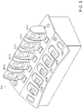
- FIG. 2 is an illustration of a vehicle having number of snow-removal components.
- FIG. 3 is a diagrammatic illustration of a control system for a snow-removal component configured to be utilized by a vehicle.
- FIG. 4 is illustration of a first user interface of a snow-removal system.
- FIG. 5 is an illustration of a second user interface of a snow-removal system.
- FIG. 6 is an illustration of a third user interface of a snow-removal system.
- FIG. 1 provides an illustration of a vehicle 100 having a number of snow-removal components.
- vehicle 100 comprises spreaders 101 and a conveyor mechanism 103 , but other embodiments may comprise other components.
- FIG. 2 provides an alternative embodiment, comprising a vehicle 200 having a first plow mechanism 201 , a second plow mechanism 203 , pre-wet liquid mechanism 205 , and an anti-ice liquid mechanism 207 .
- first plow mechanism 201 comprises a front plow and second plow mechanism 203 comprises a wing plow, but other embodiments may comprise other arrangements without deviating from the teachings disclosed herein. Some embodiments may have a different number of plows without deviating from the teachings disclosed herein,
- vehicle 100 and vehicle 200 may advantageously comprise snow-removal component having moving or adjustable modes of operation, advantageously improving the versatility and utility of the vehicles during snow removal.
- vehicle 100 may be operable to selectively activate spreaders 101 and conveyor mechanism 103 for the purpose of spreading de-icing material onto a street surface, while disengaging the components while driving over surfaces not requiring de-icing.
- vehicle 200 may advantageously be improved by permitting the adjustment of front plow 201 or wing plow 203 , or by the controlled release of de-icing material from pre-wet liquid mechanism 205 .
- Other embodiments may comprise other snow-removal components, such as a hopper, spreader, belly plow, tow plow, or other snow-removal component known to one of ordinary skill in the art without deviating from the teachings disclosed herein.
- Adjustments to these components may advantageously benefit from implementation as an electrically-controlled hydraulic (“electro-hydraulic”)) system, wherein actuators providing controlled motion to the components may comprise a hydraulic implementation controlled by an electrical data signal generated by a central controller.
- An electro-hydraulic system may advantageously permit multi-tasking operation with improved efficiency compared to a centralized hydraulic system, as each component utilizes a self-contained hydraulic subsystem.
- Control signals may be easily generated by a controller hardwired to an electric input of an electro-hydraulic actuator, providing a reliable control transmission that is relatively unaffected by temperature or environmental conditions compared to a hydraulic system.
- an electro-hydraulic implementation of the components may utilize hardwired electrical connections which arc advantageously less bulky and require less maintenance than a centralized hydraulic system.
- Such a system requires less space within an associated snow-removal vehicle, and requires less time and expenses pertaining to maintenance and repair of the transmission components of the system.
- FIG. 3 is a diagrammatic illustration of an electro-hydraulic control system according to one embodiment of the teachings herein.
- the system comprises a controller 301 in electrical communication with an actuator 303 .
- Actuator 303 may comprise an electrohydraulic valve operable to receive data commands from controller 301 via the associated electrical communication channel.
- actuator 303 may comprise an electrohydraulic valve, but other embodiments may comprise a hydraulic cylinder, a hydraulic motor, or any other embodiment known to one of ordinary skill in the art without deviating from the teachings disclosed herein.
- controller 301 is in electrical communication with a single actuator 303 . but other embodiments may comprise additional actuators without deviating from the teachings disclosed herein.
- Controller 301 is configured to generate controller data operable to control the operation of actuator 303 .
- Controller 301 may be operable to generate controller data in response to command data transmitted from a user interface 305 .
- User interface 305 may be operable to generate command data in response to receiving user input via an input device 307 .
- Controller 301 may be operable to generate control data within a set of specified. operational limits to prevent actuator 303 from operating in a manner that may be dangerous, harmful to the system, or difficult to control.
- the specified operational limits of the control data may be specified by a number of regulators 309 .
- Regulators 309 may be programmable, which may advantageously permit the system to be configurable for optimal operation within diverse environmental conditions, or with different configurations of an actuator 303 .
- regulators 309 may be programmable via a program access port, such as a universal serial bus (USB) port, controller area network (CAN) port, wireless access port, or any other configurations known to one of ordinary skill in the art without deviating from the teachings disclosed herein.
- USB universal serial bus
- CAN controller area network
- wireless access port any other configurations known to one of ordinary skill in the art without deviating from the teachings disclosed herein.
- regulators 309 may comprise a dither regulator 309 a , ramp regulator 309 b, limit regulator 309 c, and a park regulator 309 d, but other embodiments may comprise different or additional regulators without deviating from the teachings disclosed herein.
- a dither regulator 309 a may be operable to filter command data to provide continuous low-level signal to actuator 303 . Providing such a continuous low-level signal may provide smooth and reliable operation of an actuator, and may prevent stilted operation (so-called “stiction”). Dither signal may be adjustably determined by dither regulator 309 a according to a specified signal suitable for a particular configuration of actuator 303 . Embodiments comprised of multiple actuators 303 may utilize multiple dither regulators 309 a to accommodate different actuator specifications, or a single dither regulator 309 a may be operable to provide different dither signals to different command data associated with a particular actuator without deviating from the teachings disclosed herein.
- a ramp regulator 309 b may be operable to filter command data to operate an actuator 303 to provide a smooth motion for the associated moving component.
- the desired smooth motion may be achieved by limiting the acceleration the associated actuator may achieve during operation, thus limiting the acceleration of the associated moving component.
- Ramping may prevent a “jerky” motion, and improve the user's ability to reliably control the associated component.
- Ramping properties may be adjustably determined by ramp regulator 309 b according to a specified behavior suitable for a particular configuration of actuator 303 .
- Embodiments comprised of multiple actuators 303 may utilize multiple ramp regulators 309 b to accommodate different actuator specifications, or a single ramp regulator 309 b may be operable to provide different ramping filters to different command data associated with a particular actuator without deviating from the teachings disclosed herein.
- a limit regulator 309 c may be operable to filter command data to limit the speed of motion of a component associated with actuator 303 .
- Limitations on the extremes of motion for a component may advantageously prevent actuator 303 from moving faster than the safe capabilities of the component.
- Limiting the range of motion may advantageously prevent damage to actuator 303 or the associated component.
- Limiting the range of motion may advantageously improve the safety of the system with respect to a user or other persons in vicinity of the system during operation, and may improve the user's ability to reliably control the associated component.
- Limitations of the range of motion may comprise a minimum speed, a maximum speed, or both without deviating from the teachings disclosed herein.
- Speed limitations may be adjustably determined by limit regulator 309 c according to a specified behavior suitable for a particular configuration of actuator 303 .
- Embodiments comprised of multiple actuators 303 may utilize multiple limit regulators 309 c to accommodate different actuator specifications, or a single limit regulator 309 c may be operable to provide different ramping filters to different command da associated with particular actuator without deviating from teachings disclosed herein.
- a park regulator 309 d may be operable to filter command data for the purpose of operating actuator 303 to achieve a particular predetermined configuration of the system.
- park regulator 309 d may be operable to supersede controller data generated by controller 301 and instead operate actuator 303 such that the associated component is positioned into a programmed configuration, irrespective of other user input.
- the programmed configuration of park regulator 309 d may he adjusted by the user, but other embodiments may comprise other configurations without deviating from the teachings disclosed herein.
- the programmed configuration may be utilized to improve safety of the associated components when the components are not in use.
- a front plow component may have a park configuration with the plow elevated off the ground to prevent damage to the front plow and damage to the road when driving.
- Other components may comprise other park configurations without deviating from the teachings disclosed herein.
- park regulator 309 d may comprise an interlock mechanism (also called a “dead man's switch”) operable to prevent all other operation of the associated actuator while active.
- the interlock mechanism may be configured to prevent operation of the actuator in the parked position or an arbitrary position without deviating from the teachings disclosed herein.
- Some components may have multiple park configurations to address different contexts without deviating from the teachings disclosed herein.
- Embodiments comprised of multiple actuators 303 may utilize multiple park regulators 309 d to accommodate different actuator specifications, or a single park regulator 309 d may be operable to provide different ramping filters to different command data associated with a particular actuator without deviating from the teachings disclosed herein.
- FIG. 4 is an illustration of one embodiment of a user interface 400 for a system, such as the system of FIG. 3 .
- Interface 400 may comprise an input device 401 , a display 403 and display controls 405 .
- a user may operate the system by utilizing input device 401 or display controls 405 to generate command data.
- the user may receive visual interface feedback, or additional feedback via display 403 .
- input device 401 comprises a joystick configuration, but other embodiments may comprise other configurations without deviating from the teachings disclosed herein. Some embodiments may comprise multiple joysticks without deviating from the teachings disclosed herein.
- user interface 400 may be in electrical data communication with the rest of the system (not shown) via an electrical connection 407 .
- electrical connection 407 comprises a coaxial cable, but other embodiments may comprise other configurations without deviating from the teachings disclosed herein.
- Some embodiments may comprise a wireless electrical connection without deviating from the teachings disclosed herein.
- Some embodiments may utilize a controller area network (CAN) bus to electrically connect a user interface to one or more controllers without deviating from the teachings disclosed herein.
- CAN controller area network
- FIG. 5 is an illustration of another embodiment of a user interface 500 , comprising a number of axis paddles 501 and switches 503 .
- User interface 500 may advantageously provide a user with direct-access to control a plurality of system components simultaneously.
- the depicted embodiment does not comprise a display, but other embodiments may comprise a display such as display 403 (see FIG. 4 ) without deviating from the teachings disclosed herein.
- FIG. 6 is an illustration of another embodiment of a user interface 600 , comprising a number of joysticks 601 and switches 603 .
- User interface 600 may advantageously provide a user with direct-access to control a plurality of system components simultaneously.
- the depicted embodiment does not comprise a display, but other embodiments may comprise a display such as display 403 (see FIG. 4 ) without deviating from the teachings disclosed herein.
Landscapes
- Engineering & Computer Science (AREA)
- Architecture (AREA)
- Civil Engineering (AREA)
- Structural Engineering (AREA)
- Mechanical Control Devices (AREA)
- Fluid-Pressure Circuits (AREA)
- Operation Control Of Excavators (AREA)
Abstract
Description
Claims (20)
Priority Applications (2)
| Application Number | Priority Date | Filing Date | Title |
|---|---|---|---|
| US16/426,465 US11459716B2 (en) | 2018-12-20 | 2019-05-30 | Electrohydraulic actuator system for snow-removal components |
| CA3065634A CA3065634C (en) | 2018-12-20 | 2019-12-19 | Electrohydraulic actuator system for snow-removal components |
Applications Claiming Priority (2)
| Application Number | Priority Date | Filing Date | Title |
|---|---|---|---|
| US201862782988P | 2018-12-20 | 2018-12-20 | |
| US16/426,465 US11459716B2 (en) | 2018-12-20 | 2019-05-30 | Electrohydraulic actuator system for snow-removal components |
Publications (2)
| Publication Number | Publication Date |
|---|---|
| US20200199836A1 US20200199836A1 (en) | 2020-06-25 |
| US11459716B2 true US11459716B2 (en) | 2022-10-04 |
Family
ID=71097392
Family Applications (1)
| Application Number | Title | Priority Date | Filing Date |
|---|---|---|---|
| US16/426,465 Active 2041-08-04 US11459716B2 (en) | 2018-12-20 | 2019-05-30 | Electrohydraulic actuator system for snow-removal components |
Country Status (2)
| Country | Link |
|---|---|
| US (1) | US11459716B2 (en) |
| CA (1) | CA3065634C (en) |
Families Citing this family (2)
| Publication number | Priority date | Publication date | Assignee | Title |
|---|---|---|---|---|
| US20210285170A1 (en) * | 2020-03-10 | 2021-09-16 | Betts Platinum Group, PLLC, dba J-Tech | Debris Mover for Mounting on Highway Trucks |
| CN113802501A (en) * | 2021-08-12 | 2021-12-17 | 奇瑞商用车(安徽)有限公司 | Intelligent operation system of pure electric sanitation sweeper and control method thereof |
-
2019
- 2019-05-30 US US16/426,465 patent/US11459716B2/en active Active
- 2019-12-19 CA CA3065634A patent/CA3065634C/en active Active
Also Published As
| Publication number | Publication date |
|---|---|
| CA3065634A1 (en) | 2020-06-20 |
| US20200199836A1 (en) | 2020-06-25 |
| CA3065634C (en) | 2026-04-07 |
Similar Documents
| Publication | Publication Date | Title |
|---|---|---|
| US11459716B2 (en) | Electrohydraulic actuator system for snow-removal components | |
| CN104773167B (en) | Vehicle group driving control method and driving control system | |
| US9043050B2 (en) | Programmable reverse thrust detent system and method | |
| US11098491B2 (en) | Large manipulator having an articulated mast that can be quickly folded and unfolded | |
| US9330367B2 (en) | Frozen precipitation treatment analysis system | |
| WO2010012261A3 (en) | Automatic system for manoeuvring aircraft on the ground | |
| US20180004199A1 (en) | Control system for a transit mixer vehicle | |
| EP3816005A3 (en) | Adaptive speed control system | |
| CN105836107A (en) | Aircraft, systems, and methods for trim control in fly-by-wire aircraft systems | |
| US20140373666A1 (en) | Joystick With Improved Control for Work Vehicles | |
| CN110685242A (en) | Cleaning vehicle water spray pressure adjusting control method and system and cleaning vehicle | |
| JP2693852B2 (en) | Communication system for distributed electro-hydraulic system | |
| AU2004200464C1 (en) | Brake system cut-out control | |
| CN104032959B (en) | Engineering machinery and arm rest control system | |
| CN105620424A (en) | Windshield wiper system of aircraft, with rainfall signal | |
| CN208752469U (en) | A pure electric road sweeper sweeping disc device hydraulic working pressure electric control adjustment system | |
| CN108082004A (en) | For the traction control method and system of railway transportation equipment | |
| AU2016368618A1 (en) | Method for controlling a rail vehicle within a working area, control system and use of an external control device | |
| EP2307247B1 (en) | Finisher brake | |
| DE3034014A1 (en) | Launching and landing device for aircraft with no undercarriage - comprises self-powered vehicle supporting aircraft platform controlled by remote-control signals | |
| US11181126B2 (en) | Systems and methods for operating a direct current hydraulic pump | |
| CN209690757U (en) | Apply the chassis domain controller on automatic driving car | |
| CN101030332A (en) | Simulation airport | |
| KR100962088B1 (en) | An emergency operating system for sprinkler | |
| CN104648363A (en) | Vehicle compartment speed reducer and vehicle compartment with speed reducer |
Legal Events
| Date | Code | Title | Description |
|---|---|---|---|
| FEPP | Fee payment procedure |
Free format text: ENTITY STATUS SET TO UNDISCOUNTED (ORIGINAL EVENT CODE: BIG.); ENTITY STATUS OF PATENT OWNER: LARGE ENTITY |
|
| STPP | Information on status: patent application and granting procedure in general |
Free format text: DOCKETED NEW CASE - READY FOR EXAMINATION |
|
| AS | Assignment |
Owner name: BOSCH REXROTH CANADA CORPORATION, CANADA Free format text: ASSIGNMENT OF ASSIGNORS INTEREST;ASSIGNORS:ZHANG, JUN;GIESBRECHT, TIM;DE WAARD, BOYD;SIGNING DATES FROM 20190103 TO 20190110;REEL/FRAME:051504/0953 Owner name: ROBERT BOSCH GMBH, GERMANY Free format text: ASSIGNMENT OF ASSIGNORS INTEREST;ASSIGNORS:ZHANG, JUN;GIESBRECHT, TIM;DE WAARD, BOYD;SIGNING DATES FROM 20190103 TO 20190110;REEL/FRAME:051504/0953 |
|
| STPP | Information on status: patent application and granting procedure in general |
Free format text: AWAITING TC RESP., ISSUE FEE NOT PAID |
|
| STPP | Information on status: patent application and granting procedure in general |
Free format text: NOTICE OF ALLOWANCE MAILED -- APPLICATION RECEIVED IN OFFICE OF PUBLICATIONS |
|
| STPP | Information on status: patent application and granting procedure in general |
Free format text: PUBLICATIONS -- ISSUE FEE PAYMENT VERIFIED |
|
| STCF | Information on status: patent grant |
Free format text: PATENTED CASE |
|
| CC | Certificate of correction | ||
| MAFP | Maintenance fee payment |
Free format text: PAYMENT OF MAINTENANCE FEE, 4TH YEAR, LARGE ENTITY (ORIGINAL EVENT CODE: M1551); ENTITY STATUS OF PATENT OWNER: LARGE ENTITY Year of fee payment: 4 |