US11440407B2 - Non-contact operating apparatus for vehicle and vehicle - Google Patents
Non-contact operating apparatus for vehicle and vehicle Download PDFInfo
- Publication number
- US11440407B2 US11440407B2 US16/751,443 US202016751443A US11440407B2 US 11440407 B2 US11440407 B2 US 11440407B2 US 202016751443 A US202016751443 A US 202016751443A US 11440407 B2 US11440407 B2 US 11440407B2
- Authority
- US
- United States
- Prior art keywords
- occupant
- vehicle
- motion
- image
- detecting device
- Prior art date
- Legal status (The legal status is an assumption and is not a legal conclusion. Google has not performed a legal analysis and makes no representation as to the accuracy of the status listed.)
- Active
Links
Images


Classifications
-
- B—PERFORMING OPERATIONS; TRANSPORTING
- B60—VEHICLES IN GENERAL
- B60R—VEHICLES, VEHICLE FITTINGS, OR VEHICLE PARTS, NOT OTHERWISE PROVIDED FOR
- B60R16/00—Electric or fluid circuits specially adapted for vehicles and not otherwise provided for; Arrangement of elements of electric or fluid circuits specially adapted for vehicles and not otherwise provided for
- B60R16/02—Electric or fluid circuits specially adapted for vehicles and not otherwise provided for; Arrangement of elements of electric or fluid circuits specially adapted for vehicles and not otherwise provided for electric constitutive elements
- B60R16/023—Electric or fluid circuits specially adapted for vehicles and not otherwise provided for; Arrangement of elements of electric or fluid circuits specially adapted for vehicles and not otherwise provided for electric constitutive elements for transmission of signals between vehicle parts or subsystems
- B60R16/0231—Circuits relating to the driving or the functioning of the vehicle
-
- G—PHYSICS
- G06—COMPUTING OR CALCULATING; COUNTING
- G06F—ELECTRIC DIGITAL DATA PROCESSING
- G06F3/00—Input arrangements for transferring data to be processed into a form capable of being handled by the computer; Output arrangements for transferring data from processing unit to output unit, e.g. interface arrangements
- G06F3/01—Input arrangements or combined input and output arrangements for interaction between user and computer
- G06F3/011—Arrangements for interaction with the human body, e.g. for user immersion in virtual reality
-
- B—PERFORMING OPERATIONS; TRANSPORTING
- B60—VEHICLES IN GENERAL
- B60K—ARRANGEMENT OR MOUNTING OF PROPULSION UNITS OR OF TRANSMISSIONS IN VEHICLES; ARRANGEMENT OR MOUNTING OF PLURAL DIVERSE PRIME-MOVERS IN VEHICLES; AUXILIARY DRIVES FOR VEHICLES; INSTRUMENTATION OR DASHBOARDS FOR VEHICLES; ARRANGEMENTS IN CONNECTION WITH COOLING, AIR INTAKE, GAS EXHAUST OR FUEL SUPPLY OF PROPULSION UNITS IN VEHICLES
- B60K35/00—Instruments specially adapted for vehicles; Arrangement of instruments in or on vehicles
- B60K35/10—Input arrangements, i.e. from user to vehicle, associated with vehicle functions or specially adapted therefor
-
- B—PERFORMING OPERATIONS; TRANSPORTING
- B60—VEHICLES IN GENERAL
- B60K—ARRANGEMENT OR MOUNTING OF PROPULSION UNITS OR OF TRANSMISSIONS IN VEHICLES; ARRANGEMENT OR MOUNTING OF PLURAL DIVERSE PRIME-MOVERS IN VEHICLES; AUXILIARY DRIVES FOR VEHICLES; INSTRUMENTATION OR DASHBOARDS FOR VEHICLES; ARRANGEMENTS IN CONNECTION WITH COOLING, AIR INTAKE, GAS EXHAUST OR FUEL SUPPLY OF PROPULSION UNITS IN VEHICLES
- B60K35/00—Instruments specially adapted for vehicles; Arrangement of instruments in or on vehicles
- B60K35/20—Output arrangements, i.e. from vehicle to user, associated with vehicle functions or specially adapted therefor
- B60K35/21—Output arrangements, i.e. from vehicle to user, associated with vehicle functions or specially adapted therefor using visual output, e.g. blinking lights or matrix displays
- B60K35/211—Output arrangements, i.e. from vehicle to user, associated with vehicle functions or specially adapted therefor using visual output, e.g. blinking lights or matrix displays producing three-dimensional [3D] effects, e.g. stereoscopic images
-
- B—PERFORMING OPERATIONS; TRANSPORTING
- B60—VEHICLES IN GENERAL
- B60K—ARRANGEMENT OR MOUNTING OF PROPULSION UNITS OR OF TRANSMISSIONS IN VEHICLES; ARRANGEMENT OR MOUNTING OF PLURAL DIVERSE PRIME-MOVERS IN VEHICLES; AUXILIARY DRIVES FOR VEHICLES; INSTRUMENTATION OR DASHBOARDS FOR VEHICLES; ARRANGEMENTS IN CONNECTION WITH COOLING, AIR INTAKE, GAS EXHAUST OR FUEL SUPPLY OF PROPULSION UNITS IN VEHICLES
- B60K35/00—Instruments specially adapted for vehicles; Arrangement of instruments in or on vehicles
- B60K35/20—Output arrangements, i.e. from vehicle to user, associated with vehicle functions or specially adapted therefor
- B60K35/25—Output arrangements, i.e. from vehicle to user, associated with vehicle functions or specially adapted therefor using haptic output
-
- B—PERFORMING OPERATIONS; TRANSPORTING
- B60—VEHICLES IN GENERAL
- B60K—ARRANGEMENT OR MOUNTING OF PROPULSION UNITS OR OF TRANSMISSIONS IN VEHICLES; ARRANGEMENT OR MOUNTING OF PLURAL DIVERSE PRIME-MOVERS IN VEHICLES; AUXILIARY DRIVES FOR VEHICLES; INSTRUMENTATION OR DASHBOARDS FOR VEHICLES; ARRANGEMENTS IN CONNECTION WITH COOLING, AIR INTAKE, GAS EXHAUST OR FUEL SUPPLY OF PROPULSION UNITS IN VEHICLES
- B60K35/00—Instruments specially adapted for vehicles; Arrangement of instruments in or on vehicles
- B60K35/20—Output arrangements, i.e. from vehicle to user, associated with vehicle functions or specially adapted therefor
- B60K35/26—Output arrangements, i.e. from vehicle to user, associated with vehicle functions or specially adapted therefor using acoustic output
-
- B—PERFORMING OPERATIONS; TRANSPORTING
- B60—VEHICLES IN GENERAL
- B60K—ARRANGEMENT OR MOUNTING OF PROPULSION UNITS OR OF TRANSMISSIONS IN VEHICLES; ARRANGEMENT OR MOUNTING OF PLURAL DIVERSE PRIME-MOVERS IN VEHICLES; AUXILIARY DRIVES FOR VEHICLES; INSTRUMENTATION OR DASHBOARDS FOR VEHICLES; ARRANGEMENTS IN CONNECTION WITH COOLING, AIR INTAKE, GAS EXHAUST OR FUEL SUPPLY OF PROPULSION UNITS IN VEHICLES
- B60K35/00—Instruments specially adapted for vehicles; Arrangement of instruments in or on vehicles
- B60K35/20—Output arrangements, i.e. from vehicle to user, associated with vehicle functions or specially adapted therefor
- B60K35/28—Output arrangements, i.e. from vehicle to user, associated with vehicle functions or specially adapted therefor characterised by the type of the output information, e.g. video entertainment or vehicle dynamics information; characterised by the purpose of the output information, e.g. for attracting the attention of the driver
-
- B—PERFORMING OPERATIONS; TRANSPORTING
- B60—VEHICLES IN GENERAL
- B60K—ARRANGEMENT OR MOUNTING OF PROPULSION UNITS OR OF TRANSMISSIONS IN VEHICLES; ARRANGEMENT OR MOUNTING OF PLURAL DIVERSE PRIME-MOVERS IN VEHICLES; AUXILIARY DRIVES FOR VEHICLES; INSTRUMENTATION OR DASHBOARDS FOR VEHICLES; ARRANGEMENTS IN CONNECTION WITH COOLING, AIR INTAKE, GAS EXHAUST OR FUEL SUPPLY OF PROPULSION UNITS IN VEHICLES
- B60K35/00—Instruments specially adapted for vehicles; Arrangement of instruments in or on vehicles
- B60K35/80—Arrangements for controlling instruments
-
- G—PHYSICS
- G06—COMPUTING OR CALCULATING; COUNTING
- G06F—ELECTRIC DIGITAL DATA PROCESSING
- G06F3/00—Input arrangements for transferring data to be processed into a form capable of being handled by the computer; Output arrangements for transferring data from processing unit to output unit, e.g. interface arrangements
- G06F3/01—Input arrangements or combined input and output arrangements for interaction between user and computer
- G06F3/016—Input arrangements with force or tactile feedback as computer generated output to the user
-
- G—PHYSICS
- G06—COMPUTING OR CALCULATING; COUNTING
- G06F—ELECTRIC DIGITAL DATA PROCESSING
- G06F3/00—Input arrangements for transferring data to be processed into a form capable of being handled by the computer; Output arrangements for transferring data from processing unit to output unit, e.g. interface arrangements
- G06F3/01—Input arrangements or combined input and output arrangements for interaction between user and computer
- G06F3/017—Gesture based interaction, e.g. based on a set of recognized hand gestures
-
- G—PHYSICS
- G06—COMPUTING OR CALCULATING; COUNTING
- G06F—ELECTRIC DIGITAL DATA PROCESSING
- G06F3/00—Input arrangements for transferring data to be processed into a form capable of being handled by the computer; Output arrangements for transferring data from processing unit to output unit, e.g. interface arrangements
- G06F3/01—Input arrangements or combined input and output arrangements for interaction between user and computer
- G06F3/048—Interaction techniques based on graphical user interfaces [GUI]
- G06F3/0481—Interaction techniques based on graphical user interfaces [GUI] based on specific properties of the displayed interaction object or a metaphor-based environment, e.g. interaction with desktop elements like windows or icons, or assisted by a cursor's changing behaviour or appearance
- G06F3/04815—Interaction with a metaphor-based environment or interaction object displayed as three-dimensional [3D], e.g. changing the user viewpoint with respect to the environment or object
-
- G—PHYSICS
- G06—COMPUTING OR CALCULATING; COUNTING
- G06F—ELECTRIC DIGITAL DATA PROCESSING
- G06F3/00—Input arrangements for transferring data to be processed into a form capable of being handled by the computer; Output arrangements for transferring data from processing unit to output unit, e.g. interface arrangements
- G06F3/01—Input arrangements or combined input and output arrangements for interaction between user and computer
- G06F3/048—Interaction techniques based on graphical user interfaces [GUI]
- G06F3/0484—Interaction techniques based on graphical user interfaces [GUI] for the control of specific functions or operations, e.g. selecting or manipulating an object, an image or a displayed text element, setting a parameter value or selecting a range
- G06F3/04842—Selection of displayed objects or displayed text elements
-
- G—PHYSICS
- G06—COMPUTING OR CALCULATING; COUNTING
- G06F—ELECTRIC DIGITAL DATA PROCESSING
- G06F3/00—Input arrangements for transferring data to be processed into a form capable of being handled by the computer; Output arrangements for transferring data from processing unit to output unit, e.g. interface arrangements
- G06F3/01—Input arrangements or combined input and output arrangements for interaction between user and computer
- G06F3/048—Interaction techniques based on graphical user interfaces [GUI]
- G06F3/0484—Interaction techniques based on graphical user interfaces [GUI] for the control of specific functions or operations, e.g. selecting or manipulating an object, an image or a displayed text element, setting a parameter value or selecting a range
- G06F3/04847—Interaction techniques to control parameter settings, e.g. interaction with sliders or dials
-
- G—PHYSICS
- G06—COMPUTING OR CALCULATING; COUNTING
- G06F—ELECTRIC DIGITAL DATA PROCESSING
- G06F3/00—Input arrangements for transferring data to be processed into a form capable of being handled by the computer; Output arrangements for transferring data from processing unit to output unit, e.g. interface arrangements
- G06F3/01—Input arrangements or combined input and output arrangements for interaction between user and computer
- G06F3/048—Interaction techniques based on graphical user interfaces [GUI]
- G06F3/0487—Interaction techniques based on graphical user interfaces [GUI] using specific features provided by the input device, e.g. functions controlled by the rotation of a mouse with dual sensing arrangements, or of the nature of the input device, e.g. tap gestures based on pressure sensed by a digitiser
- G06F3/0488—Interaction techniques based on graphical user interfaces [GUI] using specific features provided by the input device, e.g. functions controlled by the rotation of a mouse with dual sensing arrangements, or of the nature of the input device, e.g. tap gestures based on pressure sensed by a digitiser using a touch-screen or digitiser, e.g. input of commands through traced gestures
-
- G—PHYSICS
- G06—COMPUTING OR CALCULATING; COUNTING
- G06T—IMAGE DATA PROCESSING OR GENERATION, IN GENERAL
- G06T7/00—Image analysis
- G06T7/20—Analysis of motion
-
- B—PERFORMING OPERATIONS; TRANSPORTING
- B60—VEHICLES IN GENERAL
- B60K—ARRANGEMENT OR MOUNTING OF PROPULSION UNITS OR OF TRANSMISSIONS IN VEHICLES; ARRANGEMENT OR MOUNTING OF PLURAL DIVERSE PRIME-MOVERS IN VEHICLES; AUXILIARY DRIVES FOR VEHICLES; INSTRUMENTATION OR DASHBOARDS FOR VEHICLES; ARRANGEMENTS IN CONNECTION WITH COOLING, AIR INTAKE, GAS EXHAUST OR FUEL SUPPLY OF PROPULSION UNITS IN VEHICLES
- B60K2360/00—Indexing scheme associated with groups B60K35/00 or B60K37/00 relating to details of instruments or dashboards
- B60K2360/11—Instrument graphical user interfaces or menu aspects
-
- B—PERFORMING OPERATIONS; TRANSPORTING
- B60—VEHICLES IN GENERAL
- B60K—ARRANGEMENT OR MOUNTING OF PROPULSION UNITS OR OF TRANSMISSIONS IN VEHICLES; ARRANGEMENT OR MOUNTING OF PLURAL DIVERSE PRIME-MOVERS IN VEHICLES; AUXILIARY DRIVES FOR VEHICLES; INSTRUMENTATION OR DASHBOARDS FOR VEHICLES; ARRANGEMENTS IN CONNECTION WITH COOLING, AIR INTAKE, GAS EXHAUST OR FUEL SUPPLY OF PROPULSION UNITS IN VEHICLES
- B60K2360/00—Indexing scheme associated with groups B60K35/00 or B60K37/00 relating to details of instruments or dashboards
- B60K2360/146—Instrument input by gesture
-
- B—PERFORMING OPERATIONS; TRANSPORTING
- B60—VEHICLES IN GENERAL
- B60K—ARRANGEMENT OR MOUNTING OF PROPULSION UNITS OR OF TRANSMISSIONS IN VEHICLES; ARRANGEMENT OR MOUNTING OF PLURAL DIVERSE PRIME-MOVERS IN VEHICLES; AUXILIARY DRIVES FOR VEHICLES; INSTRUMENTATION OR DASHBOARDS FOR VEHICLES; ARRANGEMENTS IN CONNECTION WITH COOLING, AIR INTAKE, GAS EXHAUST OR FUEL SUPPLY OF PROPULSION UNITS IN VEHICLES
- B60K2360/00—Indexing scheme associated with groups B60K35/00 or B60K37/00 relating to details of instruments or dashboards
- B60K2360/149—Instrument input by detecting viewing direction not otherwise provided for
-
- B—PERFORMING OPERATIONS; TRANSPORTING
- B60—VEHICLES IN GENERAL
- B60K—ARRANGEMENT OR MOUNTING OF PROPULSION UNITS OR OF TRANSMISSIONS IN VEHICLES; ARRANGEMENT OR MOUNTING OF PLURAL DIVERSE PRIME-MOVERS IN VEHICLES; AUXILIARY DRIVES FOR VEHICLES; INSTRUMENTATION OR DASHBOARDS FOR VEHICLES; ARRANGEMENTS IN CONNECTION WITH COOLING, AIR INTAKE, GAS EXHAUST OR FUEL SUPPLY OF PROPULSION UNITS IN VEHICLES
- B60K2360/00—Indexing scheme associated with groups B60K35/00 or B60K37/00 relating to details of instruments or dashboards
- B60K2360/16—Type of output information
- B60K2360/177—Augmented reality
-
- B—PERFORMING OPERATIONS; TRANSPORTING
- B60—VEHICLES IN GENERAL
- B60K—ARRANGEMENT OR MOUNTING OF PROPULSION UNITS OR OF TRANSMISSIONS IN VEHICLES; ARRANGEMENT OR MOUNTING OF PLURAL DIVERSE PRIME-MOVERS IN VEHICLES; AUXILIARY DRIVES FOR VEHICLES; INSTRUMENTATION OR DASHBOARDS FOR VEHICLES; ARRANGEMENTS IN CONNECTION WITH COOLING, AIR INTAKE, GAS EXHAUST OR FUEL SUPPLY OF PROPULSION UNITS IN VEHICLES
- B60K2360/00—Indexing scheme associated with groups B60K35/00 or B60K37/00 relating to details of instruments or dashboards
- B60K2360/20—Optical features of instruments
- B60K2360/21—Optical features of instruments using cameras
-
- B—PERFORMING OPERATIONS; TRANSPORTING
- B60—VEHICLES IN GENERAL
- B60K—ARRANGEMENT OR MOUNTING OF PROPULSION UNITS OR OF TRANSMISSIONS IN VEHICLES; ARRANGEMENT OR MOUNTING OF PLURAL DIVERSE PRIME-MOVERS IN VEHICLES; AUXILIARY DRIVES FOR VEHICLES; INSTRUMENTATION OR DASHBOARDS FOR VEHICLES; ARRANGEMENTS IN CONNECTION WITH COOLING, AIR INTAKE, GAS EXHAUST OR FUEL SUPPLY OF PROPULSION UNITS IN VEHICLES
- B60K2360/00—Indexing scheme associated with groups B60K35/00 or B60K37/00 relating to details of instruments or dashboards
- B60K2360/20—Optical features of instruments
- B60K2360/31—Virtual images
-
- B60K2370/11—
-
- B60K2370/146—
-
- B60K2370/152—
-
- B60K2370/21—
-
- B60K2370/31—
-
- B60K2370/52—
-
- B—PERFORMING OPERATIONS; TRANSPORTING
- B60—VEHICLES IN GENERAL
- B60K—ARRANGEMENT OR MOUNTING OF PROPULSION UNITS OR OF TRANSMISSIONS IN VEHICLES; ARRANGEMENT OR MOUNTING OF PLURAL DIVERSE PRIME-MOVERS IN VEHICLES; AUXILIARY DRIVES FOR VEHICLES; INSTRUMENTATION OR DASHBOARDS FOR VEHICLES; ARRANGEMENTS IN CONNECTION WITH COOLING, AIR INTAKE, GAS EXHAUST OR FUEL SUPPLY OF PROPULSION UNITS IN VEHICLES
- B60K35/00—Instruments specially adapted for vehicles; Arrangement of instruments in or on vehicles
- B60K35/20—Output arrangements, i.e. from vehicle to user, associated with vehicle functions or specially adapted therefor
- B60K35/21—Output arrangements, i.e. from vehicle to user, associated with vehicle functions or specially adapted therefor using visual output, e.g. blinking lights or matrix displays
- B60K35/22—Display screens
-
- B—PERFORMING OPERATIONS; TRANSPORTING
- B60—VEHICLES IN GENERAL
- B60K—ARRANGEMENT OR MOUNTING OF PROPULSION UNITS OR OF TRANSMISSIONS IN VEHICLES; ARRANGEMENT OR MOUNTING OF PLURAL DIVERSE PRIME-MOVERS IN VEHICLES; AUXILIARY DRIVES FOR VEHICLES; INSTRUMENTATION OR DASHBOARDS FOR VEHICLES; ARRANGEMENTS IN CONNECTION WITH COOLING, AIR INTAKE, GAS EXHAUST OR FUEL SUPPLY OF PROPULSION UNITS IN VEHICLES
- B60K35/00—Instruments specially adapted for vehicles; Arrangement of instruments in or on vehicles
- B60K35/80—Arrangements for controlling instruments
- B60K35/81—Arrangements for controlling instruments for controlling displays
-
- G—PHYSICS
- G06—COMPUTING OR CALCULATING; COUNTING
- G06T—IMAGE DATA PROCESSING OR GENERATION, IN GENERAL
- G06T2207/00—Indexing scheme for image analysis or image enhancement
- G06T2207/30—Subject of image; Context of image processing
- G06T2207/30196—Human being; Person
Definitions
- the technology relates to a non-contact operating apparatus for a vehicle and to a vehicle.
- a start switch, a handle, a shift lever, and a pedal directed to controlling of traveling of the vehicle are provided in the vicinity of a driver's seat in the vehicle.
- operating members for an air conditioner, a navigation apparatus, an audio device, an image receiving device, a handsfree calling device, and other equipment devices are provided in the vehicle.
- the large number of operating members may be laid out on an inner surface of a vehicle compartment. In recent years, however, the inner surface for layout in the vehicle compartment tends to become insufficient. For example, in a case where it is considered that a game machine, a network communication device, an entertainment device, or any other device may be added thereto, there is a possibility that operating members for these devices cannot further be added in the future.
- An aspect of the technology provides a non-contact operating apparatus, for a vehicle, that includes a generating unit, a projecting device, an operation detecting device, an operation determining unit, and a motion detecting device.
- the generating unit is configured to generate and update an image containing an image object.
- the image object is operable by an occupant present within a vehicle compartment of the vehicle.
- the projecting device is configured to project the image in a predetermined display region within the vehicle compartment of the vehicle.
- the operation detecting device is configured to detect an operation site of the occupant positioned in a vicinity of the predetermined display region within the vehicle compartment.
- the operation determining unit is configured to determine, on the basis of a position or motion of the operation site of the occupant with respect to the image object, whether the operation site of the occupant detected by the operation detecting device performs a non-contact operation against the image object.
- the motion detecting device is configured to detect motion of the vehicle or motion of the occupant caused by the motion of the vehicle.
- the operation determining unit is configured to adjust, on the basis of a detection result of the motion detecting device, a detection result of the operation detecting device to suppress the motion of the occupant caused by the motion of the vehicle.
- the operation determining unit is configured to determine presence or absence of the operation against the image object by the operation site of the occupant on the basis of the adjusted detection result.
- An aspect of the technology provides a vehicle that includes a non-contact operating apparatus and two or more control devices.
- the non-contact operating apparatus includes a generating unit, a projecting device, an operation detecting device, an operation determining unit, and a motion detecting device.
- the generating unit is configured to generate and update an image containing an image object.
- the image object is operable by an occupant present within a vehicle compartment of the vehicle.
- the projecting device is configured to project the image in a predetermined display region within the vehicle compartment of the vehicle.
- the operation detecting device is configured to detect an operation site of the occupant positioned in a vicinity of the predetermined display region within the vehicle compartment.
- the operation determining unit is configured to determine, on the basis of a position or motion of the operation site of the occupant with respect to the image object, whether the operation site of the occupant detected by the operation detecting device performs a non-contact operation against the image object.
- the motion detecting device is configured to detect motion of the vehicle or motion of the occupant caused by the motion of the vehicle.
- the operation determining unit is configured to adjust, on the basis of a detection result of the motion detecting device, a detection result of the operation detecting device to suppress the motion of the occupant caused by the motion of the vehicle.
- the operation determining unit is configured to determine presence or absence of the operation against the image object by the operation site of the occupant on the basis of the adjusted detection result.
- the two or more control devices are coupled to the non-contact operating apparatus through an internal network.
- Each of the two or more control devices is configured to control an operation of the vehicle.
- Each of the two or more control devices is configured to acquire input information from the non-contact operating apparatus through the internal network. The input information is generated on the basis of the non-contact operation of the occupant against the image object in the image. The image is projected within the vehicle compartment by the non-contact operating apparatus.
- An aspect of the technology provides a non-contact operating apparatus, for a vehicle, that includes circuitry, a projecting device, an operation detecting device, and a motion detecting device.
- the circuitry is configured to control an operation of the non-contact operating apparatus.
- the projecting device is configured to project an image containing an image object in a predetermined display region within a vehicle compartment of the vehicle.
- the image object is operable by an occupant present within the vehicle compartment.
- the operation detecting device is configured to detect an operation site of the occupant positioned in a vicinity of the predetermined display region within the vehicle compartment.
- the motion detecting device is configured to detect motion of the vehicle or motion of the occupant caused by the motion of the vehicle.
- the circuitry is configured to generate and update the image.
- the circuitry is configured to determine, on the basis of a position or motion of the operation site of the occupant with respect to the image object, whether the operation site of the occupant detected by the operation detecting device performs a non-contact operation against the image object.
- the circuitry is configured to adjust, on the basis of a detection result of the motion detecting device, a detection result of the operation detecting device to suppress the motion of the occupant caused by the motion of the vehicle.
- the circuitry is configured to determine presence or absence of the operation against the image object by the operation site of the occupant on the basis of the adjusted detection result.
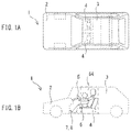
- FIGS. 1A and 1B are each a schematic explanatory diagram illustrating an example of a vehicle according to one example embodiment of the technology.
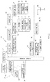
- FIG. 2 is a schematic explanatory diagram illustrating an example of a control system in the vehicle illustrated in FIG. 1 .
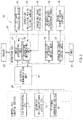
- FIG. 3 is a block diagram illustrating an example of a configuration of a non-contact operating apparatus provided in the vehicle illustrated in FIG. 1 .
- FIG. 4 is an explanatory diagram illustrating an example of arrangement of main components of the non-contact operating apparatus illustrated in FIG. 3 in a vehicle compartment.
- FIG. 5 is a flowchart illustrating an example of a flow of non-contact operation processing executed by the non-contact operating apparatus illustrated in FIG. 3 .
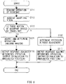
- FIG. 6 is a flowchart illustrating an example of flows of an operation determining process and a response outputting process as a determination result according to one example embodiment of the technology.
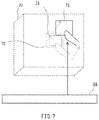
- FIG. 7 is an explanatory diagram illustrating an example of the operation determining process and the response outputting process by a tactile stimulation illustrated in FIG. 6 .
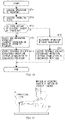
- FIG. 8 is a flowchart illustrating an example of flows of an operation determining process and a response outputting process as a determination result according to one example embodiment of the technology.
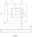
- FIG. 9 is an explanatory diagram illustrating an example of the operation determining process and the response outputting process by a tactile stimulation illustrated in FIG. 8 .
- FIG. 10 is a flowchart illustrating an example of flows of an operation determining process and a response outputting process as a determination result according to one example embodiment of the technology.
- FIG. 11 is an explanatory diagram illustrating an example of the operation determining process and the response outputting process by a tactile stimulation illustrated in FIG. 10 .
- JP-A Japanese Unexamined Patent Application Publication
- An operation apparatus for a vehicle disclosed in JP-A No. 2017-027401 described above presents an image, containing an image object, in front of an occupant who sits on a seat, and outputs a tactile stimulation based on an ultrasound field to an operation site of the occupant in response to an operation of the occupant against the presented image object. For this reason, the occupant is allowed to obtain an actual sensation of the operation against the image object.
- the vehicle travels and moves on a road.
- the traveling vehicle increases or decreases in speed, or turns right or left in order to travel smoothly.
- This causes a load to act on the vehicle.
- a load acts on the vehicle, for example, due to an increase or a decrease in speed of the vehicle, a body of the occupant moves so as to be carried in a direction of the action.
- a hand or a finger of the occupant who tries to operate the image object may be swung or shifted due to motion of the occupant caused by motion of the vehicle.
- FIGS. 1A and 1B are each a schematic explanatory diagram illustrating a vehicle 1 according to a first example embodiment of the technology.
- FIG. 1A is a top view of the vehicle 1 .
- FIG. 1B is a side view of the vehicle 1 .
- the vehicle 1 illustrated in FIGS. 1A and 1B may be one example of a vehicle.
- the vehicle 1 may include a vehicle body 2 .
- a vehicle compartment 3 may be provided in the vehicle body 2 .
- One or more occupants may be allowed to be present in the vehicle compartment 3 .
- Two or more seats 4 on each of which the occupant sits may be provided in the vehicle compartment 3 .
- a handle 5 , a shift lever 6 , a brake pedal 7 , and an accelerator pedal 8 may be provided in a front portion of the vehicle compartment 3 as operating members in order for the occupant, e.g., a driver, to operate the operating members directed to traveling of the vehicle 1 .
- the driver may sit on the seat 4 with a driving posture, and may be thereby allowed to operate any of these operating members such as the handle 5 by stretching his or her hand to the operating member.
- a hollow square frame body 64 of a stimulation output device 45 which will be described later, may be provided in the vehicle compartment 3 .
- FIG. 2 is a schematic explanatory diagram illustrating a control system 10 in the vehicle 1 illustrated in FIGS. 1A and 1B .
- FIG. 2 illustrates two or more control devices that may be included in the control system 10 as represented by control electronic control units (ECUs) incorporated in the respective two or more control devices.
- ECUs control electronic control units
- FIG. 2 illustrates a drive ECU 11 , a steering ECU 12 , a brake ECU 13 , an automatic driving/driving assist ECU 14 , a driving operation ECU 15 , a detection ECU 16 , an air-conditioning ECU 17 , an occupant monitoring ECU 18 , an external communication ECU 19 , an operation ECU 20 as a non-contact operating apparatus 40 , and a system ECU 21 .
- a vehicle network (internal network) 26 such as a controller area network (CAN) or a local interconnect network (LIN) may be adopted in the vehicle 1 .
- the above-described control ECUs may be coupled to a central gateway (CGW) 27 via the vehicle network 26 .
- the central gateway 27 may serve as a relay apparatus.
- each control ECU may be coupled to at least one electronic device used in the vehicle 1 .
- each control ECU may execute various kinds of processes to control an operation of an electronic device coupled to the corresponding control ECU on the basis of information or data acquired from the vehicle network 26 . Further, each control ECU may output information or data such as an operation state of the corresponding electronic device to the vehicle network 26 .
- Unillustrated operation detecting sensors for devices such as the handle 5 , the brake pedal 7 , the accelerator pedal 8 , or the shift lever 6 , which the occupant operates to control the traveling of the vehicle 1 , may be coupled to the driving operation ECU 15 .
- the driving operation ECU 15 may output control information based on an operation amount detected by each of the operation detecting sensors to the vehicle network 26 .
- the drive ECU 11 , the steering ECU 12 , and the brake ECU 13 may acquire necessary information from the vehicle network 26 , and control the traveling of the vehicle 1 .
- the operation ECU 20 may acquire the control information from the driving operation ECU 15 through the vehicle network 26 , and cause an unillustrated display device to display the acquired control information.
- An unillustrated operation device to be operated by the occupant may be coupled to the operation ECU 20 in addition to the display device.
- the operation ECU 20 may be included in an operating apparatus for a driving operation together with the display device and the operation device.
- the non-contact operating apparatus 40 which will be described later, may be incorporated in the operating apparatus for the driving operation.
- the operation ECU 20 may output input information against the operation device to the driving operation ECU 15 through the vehicle network 26 .
- the driving operation ECU 15 may acquire the input information through the vehicle network 26 , and execute a control based on the input information.
- a speed sensor 31 for the vehicle 1 may be coupled to the detection ECU 16 .
- the acceleration sensor 32 may detect acceleration of the vehicle 1 due to, for example, contact of the vehicle 1 .
- Each of the outer cameras 33 may capture an image of the surroundings of the vehicle 1 .
- the detection ECU 16 may output detection values acquired from the speed sensor 31 and the acceleration sensor 32 of the vehicle 1 and images acquired from the respective outer cameras 33 to the vehicle network 26 .
- the detection ECU 16 may predict contact of the vehicle 1 on the basis of the images from the outer cameras 33 , and output a prediction result to the vehicle network 26 .
- the central gateway 27 may relay various kinds of information.
- the automatic driving/driving assist ECU 14 may control traveling of the vehicle 1 until the vehicle 1 arrives at a destination for the vehicle 1 , which is set by the occupant.
- the automatic driving/driving assist ECU 14 may acquire, for example, information on the speed and the acceleration of the vehicle 1 and the images of the outer cameras 33 from the detection ECU 16 through the vehicle network 26 , and output control information for safety traveling to the vehicle network 26 .
- the drive ECU 11 , the steering ECU 12 , and the brake ECU 13 may acquire the control information for the safety traveling from the vehicle network 26 , and control the traveling of the vehicle 1 .
- the operation ECU 20 may acquire various kinds of information from the detection ECU 16 and the automatic driving/driving assist ECU 14 through the vehicle network 26 , and cause the display device to display the various kinds of information thus acquired.
- the operation ECU 20 may output the input information against the operation device to the vehicle network 26 .
- the detection ECU 16 and the automatic driving/driving assist ECU 14 may acquire the input information through the vehicle network 26 , and execute a control based on the acquired input information.
- An inner camera 34 may be coupled to the occupant monitoring ECU 18 .
- the occupant monitoring ECU 18 may identify the occupant who is present in the vehicle 1 on the basis of the image captured by the inner camera 34 , and monitor a riding state of the occupant.
- the captured image and an identification result may be information regarding the occupant.
- the information regarding the occupant is referred to as “occupant information.”
- the occupant monitoring ECU 18 may output the occupant information to the vehicle network 26 .
- the operation ECU 20 may acquire the occupant information from the occupant monitoring ECU 18 through the vehicle network 26 , and cause the display device to display the occupant information.
- the operation ECU 20 may output the input information against the operation device to the vehicle network 26 .
- the occupant monitoring ECU 18 may acquire the input information through the vehicle network 26 , and execute a control based on the acquired input information.
- the air-conditioning ECU 17 may control environment such as temperature or humidity of the vehicle compartment 3 .
- the air-conditioning ECU 17 may output in-vehicle information on temperature, an amount of solar radiation, humidity, or any other factor detected by an unillustrated sensor such as a temperature sensor to the vehicle network 26 .
- the operation ECU 20 may acquire the in-vehicle information from the air-conditioning ECU 17 through the vehicle network 26 , and cause the display device to display the acquired in-vehicle information. In a case where the occupant operates the operation device with respect to the in-vehicle information displayed by the display device, the operation ECU 20 may output the input information against the operation device to the vehicle network 26 .
- the air-conditioning ECU 17 may acquire the input information through the vehicle network 26 , and execute a control based on the acquired input information.
- the external communication ECU 19 may communicate wirelessly with any of a communication base station 81 existing outside the vehicle 1 and a communication device of another vehicle 82 , for example.
- the communication base station 81 and the communication device of the other vehicle 82 may be included in a transportation system 80 together with a server apparatus 83 .
- the external communication ECU 19 may receive information on the transportation system 80 from the communication base station 81 or the communication device of the other vehicle 82 , and output the information to the vehicle network 26 .
- the operation ECU 20 may acquire the information received by the external communication ECU 19 through the vehicle network 26 , and cause the display device to display the information.
- the operation ECU 20 may output the input information against the operation device to the vehicle network 26 .
- the external communication ECU 19 may acquire the input information through the vehicle network 26 , and transmit the input information to the communication base station 81 or the communication device of the other vehicle 82 by wireless communication.
- the transmitted information may be utilized by the server apparatus 83 or the other vehicle 82 in the transportation system 80 , for example. This makes it possible for the operation ECU 20 of the vehicle 1 , for example, to transmit and receive the information or data to and from the server apparatus 83 and the other vehicle 82 in the transportation system 80 through the external communication ECU 19 .
- control system 10 illustrated in FIG. 2 may be configured to operate by supplying of electric power from a battery 91 provided in the vehicle 1 to each of the units. Power supply lines from the battery 91 to the respective units may be spread all over the vehicle 1 together with communication cables for the vehicle network 26 , for example. In one example, electric power may be supplied to the control system 10 from a power generator or a power receiving device in addition to the battery 91 .
- the operation ECU 20 may be coupled to the control ECUs of the other control devices through the vehicle network 26 of the vehicle 1 , whereby it is possible for the operation ECU 20 to transmit and receive the information or data to and from the control ECUs of the other control devices.
- each of the control ECUs other than the operation ECU 20 may acquire the input information from the operation ECU 20 as the non-contact operating apparatus 40 through the vehicle network 26 , and control an operation of the vehicle 1 on the basis of the acquired input information.
- the operating members including the start switch, the handle 5 , the shift lever 6 , the brake pedal 7 , and the accelerator pedal 8 directed to controlling of the traveling of the vehicle 1 may be provided in the vehicle 1 .
- operating members for an air conditioner, a navigation apparatus, an audio device, an image receiving device, a handsfree calling device, and other equipment devices may also be provided in the vehicle 1 in addition to the operating members for the devices described above.
- a large number of operating members may be provided in the vehicle 1 .
- the large number of operating members may be laid out on an inner surface of the vehicle compartment 3 .
- the inner surface for layout of the vehicle compartment 3 tends to become insufficient. For example, in a case where it is considered that a game machine, a network communication device, an entertainment device, or any other device may be added thereto, there is a possibility that operating members for these devices cannot further be added in the future.
- a projected object is referred to as an “image object.”
- the non-contact operating apparatus 40 may be considered as such an operating apparatus.
- the non-contact operating apparatus 40 may project an image in a space in front of the occupant who sits on the seat 4 .
- the non-contact operating apparatus 40 may generate input information in response to an operation of the occupant against an image object in the projected image, and output the generated input information to the vehicle network 26 .
- the non-contact operating apparatus 40 may output a tactile stimulation based on an ultrasound field to an operation site of the occupant in response to the operation of the occupant against the projected image object.
- a tactile stimulation based on an ultrasound field to an operation site of the occupant in response to the operation of the occupant against the projected image object.
- the vehicle 1 may travel and move on a road or the like.
- a load acts on the vehicle 1 while traveling by increasing or decreasing in speed or turning right or left for traveling.
- a body of the occupant so moves as to be carried due to motion of the vehicle 1 .
- a hand or a finger of the occupant who tries to operate the image object may be swung or a position thereof may be shifted due to the motion of the occupant caused by the motion of the vehicle 1 .
- FIG. 3 is a block diagram illustrating a configuration of the non-contact operating apparatus 40 to be provided in the vehicle 1 illustrated in FIG. 1 .
- the non-contact operating apparatus 40 illustrated in FIG. 3 may include, for example but not limited to, an in-vehicle communication unit 41 , a timer 42 , a 3D image projecting device 43 , an operation detecting device 44 , a stimulation output device 45 , a sound output device 46 , a memory 47 , a traveling state detecting device 48 , and the operation ECU 20 to which the aforementioned devices are coupled.
- the memory 47 may be a non-volatile memory, for example, and may be coupled to the operation ECU 20 .
- Programs and data for the non-contact operating apparatus 40 may be stored in the memory 47 .
- the programs may be ones in which processes are executed by artificial intelligence (AI).
- the programs may include a learning program for AI processing.
- the data may contain, for example but not limited to, three-dimensional model data for an image to be projected during a non-contact operation.
- the three-dimensional model data may be image data for the non-contact operation, and contain a plurality of pieces of polygon data that is to be included in a surface of the model, for example.
- the operation ECU 20 may be a central processing unit (CPU), or a microcomputer such as an application specific integrated circuit (ASIC) or a digital signal processor (DSP).
- the operation ECU 20 may read out a program for the non-contact operation from the memory 47 , and execute the program. This may implement a control unit of the non-contact operating apparatus 40 in the operation ECU 20 .
- the control unit of the non-contact operating apparatus 40 may control a general operation of the non-contact operating apparatus 40 , and implement various kinds of performance for the non-contact operation in the non-contact operating apparatus 40 .
- the operation ECU 20 may implement, as the various kinds of performance for the non-contact operation, an image generating unit 51 , an operation determining unit 52 , a stimulation response output unit 53 , and a sound response output unit 54 .
- the in-vehicle communication unit 41 may be coupled to the vehicle network 26 . As illustrated in FIG. 3 , the in-vehicle communication unit 41 may transmit and receive information or data to and from the other control ECU such as the air-conditioning ECU 17 , the automatic driving/driving assist ECU 14 , or the external communication ECU 19 through the vehicle network 26 , for example. For example, the in-vehicle communication unit 41 may acquire a display instruction to display an image object for air conditioning operation from the air-conditioning ECU 17 , and output the display instruction to the operation ECU 20 .
- the other control ECU such as the air-conditioning ECU 17 , the automatic driving/driving assist ECU 14 , or the external communication ECU 19
- the in-vehicle communication unit 41 may acquire a display instruction to display an image object for air conditioning operation from the air-conditioning ECU 17 , and output the display instruction to the operation ECU 20 .
- the in-vehicle communication unit 41 may acquire a display instruction to display an image object for setting operation for automatic driving/driving assist from the automatic driving/driving assist ECU 14 , and output the display instruction to the operation ECU 20 .
- the in-vehicle communication unit 41 may acquire content data such as the three-dimensional model data from the external communication ECU 19 , and output the acquired content data to the operation ECU 20 .
- the timer 42 may measure an elapsed time or a time.
- the elapsed time or the time measured by the timer 42 may be outputted to the operation ECU 20 .
- the image generating unit 51 generates and updates an image to be projected by the 3D image projecting device 43 .
- the image generating unit 51 may acquire the three-dimensional model data from the memory 47 or the in-vehicle communication unit 41 on the basis of the display instruction inputted from the in-vehicle communication unit 41 in order to generate data of an image to be projected.
- the image generating unit 51 may generate a three-dimensional model from the acquired three-dimensional model data.
- the image generating unit 51 may determine a projected position and a direction of the three-dimensional model in the vehicle compartment 3 viewed from the occupant, and generate image data for projection from the three-dimensional model (or a stereoscopic model.)
- the image generating unit 51 may output the image data for projection to the 3D image projecting device 43 .
- the image generating unit 51 may generate a two-dimensional model (or a planar model) from two-dimensional model data, and generate image data for projection.
- the image generating unit 51 may acquire content data such as a moving image or a still image from the memory 47 or the in-vehicle communication unit 41 , generate image data of the content as a three-dimensional image (stereoscopic image) or a two-dimensional image (planar image), and output the image data to the 3D image projecting device 43 .
- the 3D image projecting device 43 projects the 3D (three-dimensional) image or the 2D (two-dimensional) image, which is operable by the occupant, to a space, that is, a predetermined display region, within the vehicle compartment 3 of the vehicle 1 .
- the 3D image projecting device 43 may be a display device or a projector, for example.
- the 3D image projecting device 43 may project an image to a hollow space within the vehicle compartment 3 by a hologram system or a mirror system, for example.
- the 3D image projecting device 43 may be disposed at a position in front of the seat 4 on which the occupant sits, for example but not limited to, on a dashboard, a rearview mirror, a back mirror, or a roof of the vehicle compartment 3 .
- the 3D image projecting device 43 projects the 3D (three-dimensional) image or the 2D (two-dimensional) image to the space within the vehicle compartment 3 of the vehicle 1 .
- the stereoscopic image may be projected to the projected position of the vehicle compartment 3 so that the occupant is allowed to visually recognize the three-dimensional model.
- the operation detecting device 44 detects a predetermined operation site of the occupant.
- the operation detecting device 44 may detect motion of a body, an upper body, a shoulder, a head of the occupant, which may swing due to a load onto the vehicle 1 .
- the operation detecting device 44 may detect the operation site of the occupant who performs the non-contact operation against the image object of the image projected in the space within the vehicle compartment 3 .
- the non-contact operation may include, for example but not limited to, a hand operation against the image object and a movement operation to move the image object.
- the operation detecting device 44 may be disposed at a position in front of the seat 4 on which the occupant sits, for example but not limited to, on the dashboard, the rearview mirror, the back mirror, or the roof of the vehicle compartment 3 , for example.
- the operation detecting device 44 may also be used as the inner camera 34 .
- the operation detecting device 44 may include a stereo camera 63 in which two imaging devices are arranged side by side, for example.
- the operation detecting device 44 may detect, by the images of the two imaging devices, an operation by a predetermined operation site of the occupant against an image projected in midair of the vehicle compartment 3 .
- the aforementioned operation by the predetermined operation site of the occupant may be referred to also as an “operation of the occupant,” and the aforementioned image projected in midair of the vehicle compartment 3 may be referred to also as a “projected image.”
- the operation determining unit 52 may acquire detected information such as the image of the stereo camera 63 from the operation detecting device 44 , for example, and determine the non-contact operation of the occupant against the image object in the image projected in the space within the vehicle compartment 3 on the basis of the detected information.
- the operation determining unit 52 may determine, for example, a position and motion of the operation site of the occupant as the operation of the occupant against the image object projected in the space within the vehicle compartment 3 .
- the motion may include information on motion of the operation site, such as a direction, a speed, or an acceleration of movement.
- the operation determining unit 52 may acquire a pixel position including a feature of a fingertip of the occupant from the image by AI processing, for example, and generate positional information on the fingertip by a triangulation method for the image of the stereo camera 63 .
- the operation determining unit 52 may generate information on motion of the fingertip, for example, a movement direction, a movement speed, an acceleration of the movement from an imaging result obtained by shifting a time.
- the operation determining unit 52 may determine, for example, the position and the motion of the operation site of the occupant on the basis of the projected position of the image object, and determine the operation of the occupant against the image object projected in the space within the vehicle compartment 3 .
- the operation determining unit 52 may determine, for example but not limited to, presence or absence of contact of the operation site of the occupant against the projected image object, a remaining distance to contact, and a depth to contact. Information related to the presence or absence of contact of the operation site of the occupant against the projected image object, the remaining distance to contact, the depth to contact, and any other suitable information may be hereinafter referred to as “operational information.”
- the operation determining unit 52 may output the determined operational information to the respective units of the operation ECU 20 . Namely, the operation determining unit 52 may output the operational information to the image generating unit 51 , the stimulation response output unit 53 , and the sound response output unit 54 , for example.
- the operation determining unit 52 and the operation detecting device 44 may serve as a “detecting device.”
- the image generating unit 51 updates the image data for projection in response to the operation of the occupant, and may output the updated image data to the 3D image projecting device 43 .
- the image to be projected by the 3D image projecting device 43 in the predetermined display region within the vehicle compartment 3 may be updated in response to the operation of the occupant.
- the operation determining unit 52 may output input information based on the operation of the occupant to the respective ECUs of the vehicle 1 through the in-vehicle communication unit 41 .
- the operation determining unit 52 may generate input information corresponding to the operation button, and output the generated input information to the in-vehicle communication unit 41 .
- the in-vehicle communication unit 41 may output the input information to the air-conditioning ECU 17 as the control device through the vehicle network 26 .
- the air-conditioning ECU 17 may vary target set temperature for the air conditioner on the basis of the input information, and so execute an air-conditioning control that the temperature in the vehicle compartment 3 becomes the target set temperature.
- the traveling state detecting device 48 may detect a traveling state of the vehicle 1 .
- the traveling state detecting device 48 may detect, as the traveling state of the vehicle 1 , motion of the vehicle 1 due to the traveling, for example.
- Information on the motion of the vehicle 1 due to the traveling may include, for example but not limited to, weight acting on the vehicle 1 , a speed of the vehicle 1 , an acceleration of the vehicle 1 , and a yaw rate.
- the stimulation output device 45 may be so arranged as to correspond to the operation site of the occupant who operates the image object.
- the stimulation output device 45 may be any device that is configured to output, for example, by an electrical signal, a tactile stimulation to the operation site of the occupant.
- a tactile stimulation to the operation site of the occupant.
- the stimulation output device 45 may include an element array in which a plurality of ultrasonic elements 65 is arranged in a planar manner as illustrated in FIG. 4 , for example.
- the stimulation output device 45 may be provided at a position apart from and under the operation site, such as the hand, of the occupant who is present in the vehicle compartment 3 , for example.
- the stimulation response output unit 53 may cause the stimulation output device 45 to output the tactile stimulation based on the ultrasound field to the operation site of the occupant who operates the projected image object. Namely, the stimulation response output unit 53 may cause the stimulation output device 45 to output the tactile stimulation as a response to the operation of the occupant against the image object.
- the stimulation response output unit 53 may output an electrical signal to the stimulation output device 45 , and cause one or more of the plurality of ultrasonic elements 65 to selectively output ultrasound waves based on the operation. Thereby, the stimulation response output unit 53 is allowed to generate an ultrasound field in a predetermined region within the vehicle compartment 3 .
- the stimulation response output unit 53 may locally apply the field of the ultrasound waves or the variation in the field to the operation site of the occupant that is determined to be in contact with the image object by the operation determining unit 52 .
- the stimulation response output unit 53 may be able to cause the stimulation output device 45 to output, as a response to the operation, a stimulation of a tactile sensation by the ultrasound field to the operation site of the occupant that performs the non-contact operation against the image object projected in the space within the vehicle compartment 3 .
- the stimulation response output unit 53 may locally apply the field of the ultrasound waves or the variation in the field to a surface of the image object with which the operation site of the occupant is virtually in contact, for example.
- the stimulation output device 45 may include an element array in which a plurality of pressure output elements is arranged.
- the stimulation response output unit 53 may control operations of the plurality of pressure output elements separately, whereby a pressure acts on the skin of the person. This makes it possible for the occupant to obtain feeling based on the operation.
- the sound output device 46 may be a speaker, for example.
- the speaker may be driven by a sound signal.
- the sound output device 46 may output a sound based on the operation of the occupant, for example. It may be sufficient that the sound output device 46 is arranged in the vehicle compartment 3 .
- the sound response output unit 54 may output a sound signal to the sound output device 46 to output a sound based on the operation from the sound output device 46 .
- the sound response output unit 54 may select and acquire audio data recorded in the memory 47 in response to the operation of the occupant, and output a sound signal generated from the acquired audio data to the speaker as the sound output device 46 . This allows the occupant to hear various kinds of sounds based on the operation.
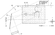
- FIG. 4 is an explanatory diagram illustrating an example of arrangement of main components of the non-contact operating apparatus 40 illustrated in FIG. 3 in the vehicle compartment 3 .
- FIG. 4 schematically illustrates one example of a specific but non-limiting combination of the 3D image projecting device 43 , the operation detecting device 44 , and the stimulation output device 45 , which are illustrated in FIG. 3 .
- FIG. 4 illustrates a display screen 61 and a half mirror 62 as the 3D image projecting device 43 .
- FIG. 4 also illustrates the stereo camera 63 as the operation detecting device 44 .
- FIG. 4 also illustrates an element array as the stimulation output device 45 .
- the aforementioned main components of the non-contact operating apparatus 40 may be provided within the vehicle compartment 3 of the vehicle 1 .
- the stimulation output device 45 may have the hollow square frame body 64 .
- An element array in which the plurality of ultrasonic elements 65 is regularly arranged, for example, may be provided on each of four surfaces of the square frame body 64 .
- an ultrasound field may locally act on a fingertip entering the inside of the square frame body 64 . This makes it possible for the occupant to obtain a tactile sensation as if the fingertip is touched by something.
- the half mirror 62 may be provided in front of the hollow square frame body 64 of the stimulation output device 45 .
- the half mirror 62 may be so provided as to face the occupant.
- the display screen 61 configured to display a three-dimensional image (stereoscopic image) or a two-dimensional image (planar image) may be disposed under the half mirror 62 .
- the image displayed on the display screen 61 may be reflected by the half mirror 62 , whereby the occupant may be allowed to visually recognize the three-dimensional image (stereoscopic image) or the two-dimensional image (planar image) inside the hollow square frame body 64 in the stimulation output device 45 .
- the occupant may be allowed to visually recognize the image projected inside the hollow square frame body 64 in the stimulation output device 45 and in midair within the vehicle compartment 3 .
- the occupant may be allowed to visually recognize that a sphere indicated by a circle in FIG. 4 as the three-dimensional image is floating inside the hollow square frame body 64 .
- the stereo camera 63 may be provided on the opposite side of the half mirror 62 with respect to the stimulation output device 45 , for example.
- the two imaging devices of the stereo camera 63 may be allowed to capture, for example, images of a finger of the occupant that is present inside the square frame body 64 .
- the stereo camera 63 may be allowed to capture an image of, for example, the finger of the occupant that enters the hollow square frame body 64 of the stimulation output device 45 .
- a direction from an axial center of the square frame body 64 toward the occupant may be referred to as a Z direction
- directions perpendicular to the Z direction may be referred to as a Y direction and an X direction.
- the Z direction may usually become a direction along a front-back direction of the vehicle 1 .
- components of the non-contact operating apparatus 40 illustrated in FIG. 3 are not necessarily arranged so as to be crowded as illustrated in FIG. 4 .
- the hollow square frame body 64 of the stimulation output device 45 may become an encumbrance to an operation when the occupant operates the operating member such as the handle 5 .
- the hollow square frame body 64 may be provided in a square frame shape along peripheral surfaces of the vehicle body 2 .
- any structural object such as the square frame body 64 may not be provided in front of the seat 4 on which the occupant sits.
- the 3D image projecting device 43 may be allowed to project an image in a space inside the hollow square frame body 64 provided within the vehicle compartment 3 , for example.
- the occupant may be allowed to perform the non-contact operation against the image object by operating the image object in the operation region inside the square frame body 64 .
- the hollow square frame body 64 may not necessarily have a square frame shape.
- the element array may merely be arranged along the peripheral surfaces of the vehicle body 2 . In an alternative example, the element array may be disposed on the inner surface of the vehicle compartment 3 as a whole.
- the half mirror 62 may basically be so provided as to oppose the occupant with the hollow square frame body 64 of the stimulation output device 45 in between. Further, if the image is merely projected in midair inside the square frame body 64 , a fully-reflective mirror may be used in place of the half mirror 62 . Further, in one example, the display screen 61 itself may be disposed at a position opposing the occupant with the hollow square frame body 64 of the stimulation output device 45 in between. In this case, the half mirror 62 or the fully-reflective mirror may not be required. In one example, the half mirror 62 or the fully-reflective mirror and the display screen 61 may be disposed on the dashboard, the rearview mirror, or the roof, for example. Further, the half mirror 62 or the fully-reflective mirror and the display screen 61 may be integrated with the occupant monitoring apparatus.
- the operation detecting device 44 such as the stereo camera 63 may be disposed on the dashboard, the rearview mirror, or the back mirror, for example. Further, the operation detecting device 44 may be used also as an imaging device of the occupant monitoring apparatus such as a display management system (DMS).
- the operation detecting device 44 such as the stereo camera 63 may be any device as long as the device is able to capture an image of an operation site such as the fingertip of the occupant. Further, a detected medium for the operation detecting device 44 is not limited to an image. For example, the inside of the vehicle compartment 3 may be scanned by laser, and a site such as a fingertip of the occupant may be detected on the basis of a scanning result.
- FIG. 5 is a flowchart illustrating a flow of non-contact operation processing executed by the non-contact operating apparatus 40 illustrated in FIG. 3 .
- Step ST 1 the operation ECU 20 may determine whether a non-contact operation against an image object in an image by projecting the image is to be started. For example, in a case where a display instruction is inputted from any ECU or in a case where there is the content to be displayed, the operation ECU 20 may determine that the non-contact operation is to be started (Y in Step ST 1 ), and cause the processing flow to proceed to Step ST 2 . Otherwise, the operation ECU 20 may determine that the non-contact operation is not to be started (N in Step ST 1 ), and terminate the non-contact operation processing illustrated in FIG. 5 .
- Step ST 2 the operation ECU 20 generates, as the image generating unit 51 , an initial 3D image, and may cause the 3D image projecting device 43 to display the 3D image.
- the operation ECU 20 may generate a three-dimensional model from three-dimensional model data acquired from the memory 47 or the in-vehicle communication unit 41 , and further generate image data for projection.
- the operation ECU 20 may generate the image data for projection from the three-dimensional model on the basis of settings of an initial projected position and an initial display direction of the image which are set for the three-dimensional model in advance. In one example, the operation ECU 20 may temporarily store the generated three-dimensional model in the memory 47 . In this case, the operation ECU 20 may read out the three-dimensional model from the memory 47 in a next generating process directed to updating of the image. This makes it possible to generate the image data for projection. The operation ECU 20 may output the generated image data for projection to the 3D image projecting device 43 . The 3D image projecting device 43 projects an image based on the image data for projection in a space within the vehicle compartment 3 .
- the three-dimensional model may be displayed at the standard projected position in front of the occupant in a predetermined display direction.
- the standard projected position refers to a position at which the image is projected in front of the occupant with the driving posture.
- the predetermined display direction may be so set that a front surface of the three-dimensional model is directed toward the occupant, for example.
- the occupant with the driving posture may be allowed to touch the image object by merely stretching his or her hand.
- the operation ECU 20 may determine, as the operation determining unit 52 , whether an operation of the occupant against an image object in the image is detected.
- the operation of the occupant may be acquired from the operation detecting device 44 .
- the operation ECU 20 may acquire detected information such as an image of the stereo camera 63 from the operation detecting device 44 , for example, and extract a predetermined operation site of the occupant such as a fingertip of the occupant, for example.
- the operation ECU 20 may thereafter detect the operation of the occupant against the image object on the basis of variation of a position of the predetermined operation site in the vehicle compartment 3 or presence or absence of motion thereof, for example.
- the operation ECU 20 may determine that the operation of the occupant against the image object is detected even though the operation site of the occupant does not operate the image object. In a case where the operation of the occupant against the image object is not detected (N in Step ST 3 ), the operation ECU 20 may repeat this determination process in Step ST 3 . In a case where the operation of the occupant against the image object is detected (Y in Step ST 3 ), the operation ECU 20 may cause the processing flow to proceed to Step ST 4 .
- the operation ECU 20 may determine, as the operation determining unit 52 , the operation of the occupant against the image object.
- the operation ECU 20 may first determine whether the operation site of the occupant is in a state where the operation site is in contact with the image object, on the basis of a projected position of a surface of the projected image. In a case where it is determined that the operation site is in the state where the operation site is in contact with the image object, the operation ECU 20 may further determine a contact shape, a position and motion (including a direction and a speed) of the operation site.
- the contact shape may be the number of fingers that are in contact with the image object, or a position of the hand, for example.
- the operation ECU 20 may determine, on the basis of the projected position of the surface of the projected image, a remaining distance to a point where the operation site comes into contact with the image object, or a depth at which the operation site is in contact with the image object, for example.
- the operation ECU 20 may generate input information inputted by the operation of the occupant.
- the operation ECU 20 may output, as the operation determining unit 52 , the determined operational information on the operation of the occupant and the input information inputted by the operation to inside and outside of the operation ECU 20 .
- the operation ECU 20 may output the operational information to the image generating unit 51 , the stimulation response output unit 53 , and the sound response output unit 54 in the operation ECU 20 . Further, the operation ECU 20 may output the input information to each of the control ECUs of the plurality of control devices provided in the respective units of the vehicle 1 through the in-vehicle communication unit 41 .
- Step ST 6 the operation ECU 20 may output a tactile stimulation, a sound, or both as a response to the operation on the basis of the operational information.
- the operation ECU 20 may specify, as the stimulation response output unit 53 , a position of the operation site of the occupant in the state of being in contact with the image object, on the basis of the operational information.
- the operation ECU 20 may thereafter select the plurality of ultrasonic elements 65 that is to output ultrasound waves so that the ultrasound waves are outputted toward the specified position, and output an electrical signal to the stimulation output device 45 .
- the stimulation output device 45 may output the ultrasound waves from the plurality of ultrasonic elements 65 thus selected.
- the occupant is allowed to obtain, on the basis of the response by the ultrasound waves, a tactile sensation as if the occupant operates the image object.
- the operation ECU 20 may select, as the sound response output unit 54 , audio data from the memory 47 in accordance with the motion of the operation site of the occupant, which is in a state where the operation site is in contact with the image object specified on the basis of the operational information, and a contact portion between the operation site and the image object. Further, the operation ECU 20 may output a sound signal generated from the audio data to the sound output device 46 . The sound output device 46 may output a sound based on the sound signal to the vehicle compartment 3 . This makes it possible for the occupant to hear, as a response sound against the operation, a different sound based on the motion of the operation site of the occupant and the contact portion between the operation site and the image object.
- Step ST 7 the operation ECU 20 updates, as the image generating unit 51 , the image data to be projected for the response to the operation of the occupant, on the basis of the operational information.
- the operation ECU 20 may read out the three-dimensional model stored in the memory 47 to update the image data for projection, and output the updated image data to the 3D image projecting device 43 .
- the 3D image projecting device 43 projects the updated image to the space within the vehicle compartment 3 . This makes it possible for the occupant to visually recognize that the occupant oneself operates the image object by the operation site on the basis of variation in the projected image.
- the operation ECU 20 may so update the image data to be projected and the output of the stimulation that the image data to be projected and the output of the stimulation are synchronized with each other in accordance with the same operational information on the operation site of the occupant detected by the operation detecting device 44 and determined by the operation determining unit 52 .
- Step ST 8 the operation ECU 20 may determine whether the non-contact operation is to be terminated. For example, in a case where outputting of the input information based on the operation is completed, in a case where any new display instruction is not inputted, or in a case where the displayed content is to be terminated, the operation ECU 20 may determine that the non-contact operation is to be terminated (Y in Step ST 8 ), and terminate the processing flow illustrated in FIG. 5 . Otherwise (N in Step ST 8 ), the operation ECU 20 may cause the processing flow to return to Step ST 3 . Thereby, the operation ECU 20 may repeat the processes from Step ST 3 to Step ST 8 until it is determined in Step ST 8 that the non-contact operation is to be terminated.
- the operation ECU 20 may appropriately repeat the respective processes of the response by the stimulation to the operation site of the occupant, the response by the sound, and the response by the update of the projected image, in response to the operation of the occupant against the image object. Namely, when the projected image is updated in response to the operation, the operation ECU 20 may so vary the output of the tactile stimulation by the ultrasound field as to correspond to the updated projected image.
- the tactile stimulation by the ultrasound field may be so controlled synchronously as to follow update of the image.
- FIG. 6 is a flowchart illustrating an example of flows of an operation determining process and a response outputting process as a determination result according to the first example embodiment.
- the processes illustrated in FIG. 6 may correspond to the processes from Step ST 4 to Step ST 6 , which are surrounded by a dotted square frame in FIG. 5 .
- the process to output the input information to the outside in Step ST 5 and the sound response outputting process in Step ST 6 are omitted.
- Step ST 11 the operation ECU 20 may acquire, as the operation determining unit 52 , information on an operation of the occupant from the operation detecting device 44 in order to determine the operation.
- Step ST 12 the operation ECU 20 may further acquire, as the operation determining unit 52 , information on a traveling state from the traveling state detecting device 48 in order to determine the operation.
- Step ST 13 the operation ECU 20 may determine, as the operation determining unit 52 , whether there is motion such as swing of the occupant caused by traveling of the vehicle 1 on the basis of the information acquired from the traveling state detecting device 48 .
- the operation ECU 20 may determine that there is no motion of the occupant caused by traveling of the vehicle 1 . In this case, the operation ECU 20 may cause the processing flow to proceed to Step ST 16 .
- the operation ECU 20 may determine that there is motion of the occupant caused by traveling of the vehicle 1 . In this case, the operation ECU 20 may cause the processing flow to proceed to Step ST 14 .
- the operation ECU 20 may determine, as the operation determining unit 52 , presence or absence of the operation against the image object by the occupant without adjusting operational information on the detected operation of the occupant.
- the operation ECU 20 may determine whether the operation site of the occupant is in a state where the operation site is in contact with an inputtable region by using the inputtable region.
- the inputtable region may be set with respect to the image object.
- the operation ECU 20 may further determine, as the operation determining unit 52 , a contact shape, a position and motion (including a direction and a speed) of the operation site.
- the operation ECU 20 may generate input information based on the operation of the occupant.
- Step ST 17 the operation ECU 20 may execute a response output to the operation determined in Step ST 16 .
- the operation ECU 20 may specify, as the stimulation response output unit 53 , a tactile stimulation for the operation determined in Step ST 16 , and instruct the stimulation output device 45 to output the specified tactile stimulation to a position of the operation site used for the determination in Step ST 16 .
- the operation ECU 20 may instruct the stimulation output device 45 to output the tactile stimulation to the position of the operation site of the occupant, which is not adjusted, on the basis of a detection result of the traveling state detecting device 48 .
- the operation ECU 20 may adjust, as the operation determining unit 52 , operational information on the detected operation of the occupant, and determine presence or absence of the operation against the image object by the occupant.
- the operation ECU 20 may correct a position of the inputtable region of the image object on the basis of the motion of the occupant caused by the motion of the vehicle 1 detected by the traveling state detecting device 48 , thereby adjusting the operational information on the operation against the image object by the occupant. Thereafter, the operation ECU 20 may determine whether the operation site of the occupant operates the inputtable region at the corrected position on the basis of the operational information of the occupant against the image object detected by the operation detecting device 44 . This makes it possible to determine presence or absence of the operation that the occupant tries to make against the image object.
- the operation ECU 20 may determine, as the operation determining unit 52 , presence or absence of the operation against the image object by the occupant on the basis of the operation of the occupant after the position of the inputtable region is corrected, thereby determining whether the operation site of the occupant is in the state where the operation site is in contact with the image object. In a case where it is determined that the operation site is in a state of operating the image object, the operation ECU 20 may further determine, as the operation determining unit 52 , a contact shape, a position, and motion (including a direction and a speed) of the operation site.
- the operation ECU 20 may generate input information based on the operation of the occupant.
- Step ST 15 the operation ECU 20 may execute a response output based on a tactile stimulation against the operation of the occupant determined in Step ST 14 .
- the operation ECU 20 may specify, as the stimulation response output unit 53 , a tactile stimulation against the operation determined in Step ST 14 , and instruct the stimulation output device 45 to output the specified tactile stimulation to the position of the operation site detected by the operation detecting device 44 .
- the operation ECU 20 may instruct the stimulation output device 45 not to output the tactile stimulation to the position of the operation site of the occupant adjusted on the basis of the detection result of the traveling state detecting device 48 , but to output the tactile stimulation to the operation site of the occupant actually detected by the operation detecting device 44 .
- the operation ECU 20 may instruct the stimulation output device 45 to output the tactile stimulation against the operation of the occupant to a wider range compared with a case where the motion is determined without adjusting the operational information on the basis of the detection result of the traveling state detecting device 48 as in Step ST 16 .
- FIG. 7 is an explanatory diagram illustrating an example of the operation determining process and the response outputting process by a tactile stimulation illustrated in FIG. 6 .
- the unillustrated 3D image projecting device 43 may project an image of a cube 70 as the image object in front of the occupant.
- the cube 70 may have a button 71 on a certain operation face.
- the operation ECU 20 may set, as the operation determining unit 52 , an inputtable region 72 at a position of the projected button 71 .
- the inputtable region 72 is illustrated by a broken line in FIG. 7 .
- a size of the inputtable region 72 may be larger than that of the button 71 .
- the operation ECU 20 may determine, as the operation determining unit 52 , presence or absence of an operation against this inputtable region 72 by the occupant.
- the operation ECU 20 may determine, as the operation determining unit 52 , that the button 71 is operated in a case where a fingertip of the occupant so moves as to come into contact with the inputtable region 72 , for example.
- the operation ECU 20 may cause the inputtable region 72 to move from an initial position at which the inputtable region 72 overlaps the button 71 to an offset position based on the motion of the occupant.
- An offset direction from the initial position of the inputtable region 72 may be the same or approximately the same direction as the motion of the occupant caused by the motion of the vehicle 1 detected by the traveling state detecting device 48 .
- An offset amount from the initial position of the inputtable region 72 may be the same or approximately the same amount as an amount of the motion of the occupant caused by the motion of the vehicle 1 detected by the traveling state detecting device 48 .
- a finger by which the occupant tries to operate the button 71 may be shifted in an upper right direction in FIG. 7 due to the motion of the vehicle 1 to touch the image object.
- the operation ECU 20 may cause the inputtable region 72 to move from the initial position to the offset position in the upper right direction, and determine presence or absence of the operation against the button 71 by the occupant on the basis of a position of an inputtable region 73 after movement.
- the operation ECU 20 can accurately determine the operation against the button 71 by the occupant on the basis of the position of the inputtable region 73 so as to cancel the motion of the occupant caused by the motion of the vehicle 1 .
- the offset direction may be a lateral direction of the vehicle body 2 .
- the offset direction may be a front-back direction of the vehicle body 2 .
- the offset amount may be proportional to the amount of the motion of the occupant caused by the motion of the vehicle 1 .
- the offset amount may be set to about a several millimeters in a case of the maximum acceleration that is assumed to be capable of acting on the occupant while normal traveling of the vehicle 1 .
- the operation determining unit 52 may determine whether there is motion of the vehicle 1 or overall motion of the occupant caused by the motion of the vehicle 1 on the basis of the information acquired from the traveling state detecting device 48 as a motion detecting device. Thereafter, the operation determining unit 52 may so adjust the operational information of the occupant as to suppress the motion of the occupant caused by the motion of the vehicle 1 , on the basis of the detection result of the traveling state detecting device 48 , and determine presence or absence of the operation against the image object projected in midair within the vehicle compartment 3 by the operation site of the occupant based on the detection result of the operation detecting device 44 .
- the non-contact operating apparatus 40 for the vehicle 1 according to a second example embodiment of the technology will be described.
- elements corresponding to those in the first example embodiment described above are denoted with the same numerals as those in the first example embodiment to avoid any redundant description.
- FIG. 8 is a flowchart illustrating an example of flows of an operation determining process and a response outputting process as a determination result according to the second example embodiment.
- Step ST 21 the operation ECU 20 may adjust, as the operation determining unit 52 , detected operational information of the occupant, and determine presence or absence of an operation against an image object by the occupant.
- Step ST 22 the operation ECU 20 may use the inputtable region set for the projected image object, and determine, as the operation determining unit 52 , whether an operation site of the occupant is in a state where the operation site is in contact with the inputtable region.
- the process in Step ST 22 is similar to the process in Step ST 16 .
- the operation ECU 20 may correct a range of the inputtable region of the image object on the basis of motion of the occupant caused by motion of the vehicle 1 detected by the traveling state detecting device 48 , and adjust information on the motion of the occupant. Further, the operation ECU 20 may so adjust the inputtable region as to enlarge the inputtable region in accordance with a magnitude of the motion of the occupant caused by the motion of the vehicle 1 .
- the operation ECU 20 may determine whether the occupant perform an operation against the inputtable region whose range is enlarged, on the basis of the operation of the occupant detected by the operation detecting device 44 . This makes it possible to accurately determine the operation that the occupant tries to perform against the image object.
- the operation ECU 20 may determine presence or absence of the operation by the occupant against the inputtable region whose range is enlarged, thereby determining whether the operation site of the occupant is in a state where the operation site is in contact with the image object. Thereafter, in a case where it is determined that the operation site is in a state where the operation site operates the image object, the operation ECU 20 may further determine a contact shape, a position, and motion (including a direction and a speed) of the operation site.
- the operation ECU 20 may generate input information on the operation of the occupant.
- Step ST 15 the operation ECU 20 may execute a response output based on a tactile stimulation against the operation of the occupant determined in Step ST 21 .
- the operation ECU 20 may instruct the stimulation output device 45 not to output the tactile stimulation to the position of the operation site of the occupant adjusted on the basis of a detection result of the traveling state detecting device 48 , but to output the tactile stimulation to the operation site of the occupant actually detected by the operation detecting device 44 .
- the operation ECU 20 may instruct the stimulation output device 45 to output a tactile stimulation in response to the operation of the occupant to a wider range compared with a case where presence or absence of the operation is determined without adjusting the operational information on the basis of the detection result of the traveling state detecting device 48 as in Step ST 22 .
- FIG. 9 is an explanatory diagram illustrating an example of the operation determining process and the response outputting process by a tactile stimulation illustrated in FIG. 8 .
- the unillustrated 3D image projecting device 43 may projects an image of the cube 70 as the image object in front of the occupant.
- the cube 70 may have the button 71 on a certain operation face.
- the operation ECU 20 may set, as the operation determining unit 52 , the inputtable region 72 at a position of the projected button 71 .
- the inputtable region 72 is illustrated by a broken line in FIG. 9 .
- the operation ECU 20 may determine, as the operation determining unit 52 , presence or absence of an operation against this inputtable region 72 by the occupant. For example, when a fingertip of the occupant so moves as to come into contact with the inputtable region 72 , the operation ECU 20 may determine, as the operation determining unit 52 , that a finger of the occupant operates the button 71 .
- the operation ECU 20 may enlarge the inputtable region 72 from an initial size.
- An enlargement ratio of the inputtable region 72 from the initial size may be a rate corresponding to an amount of the motion of the occupant caused by the motion of the vehicle 1 detected by the traveling state detecting device 48 .
- the inputtable region 72 may be enlarged in all of upper, lower, right, and left directions. Otherwise, for example, the inputtable region 72 may be enlarged only in the same direction as that of the motion of the occupant caused by the motion of the vehicle 1 detected by the traveling state detecting device 48 .
- the operation ECU 20 may enlarge the inputtable region 72 only in the upper-lower direction.
- the finger by which the occupant tries to operate the button 71 may be in contact with a portion in an upper right direction of the inputtable region 72 illustrated in FIG. 9 due to the motion of the vehicle 1 .
- the operation ECU 20 may enlarge the inputtable region 72 from the initial size, and determine presence or absence of the operation against the button 71 by the occupant on the basis of an inputtable region 74 after enlargement.
- the operation ECU 20 can determine presence or absence of the operation against the button 71 by the occupant on the basis of the inputtable region 74 by suppressing an influence of the motion of the occupant caused by the motion of the vehicle 1 .
- the operation determining unit 52 may determine whether there is motion of the vehicle 1 or overall motion of the occupant caused by the motion of the vehicle 1 , on the basis of the information acquired from the traveling state detecting device 48 as a motion detecting device. Further, the operation determining unit 52 may so adjust the operational information of the occupant as to suppress the motion of the occupant caused by the motion of the vehicle 1 , on the basis of the detection result of the traveling state detecting device 48 , and determine presence or absence of the operation against the image object projected in midair within the vehicle compartment 3 by the operation site of the occupant based on the detection result of the operation detecting device 44 .
- the non-contact operating apparatus 40 for the vehicle 1 according to a third example embodiment of the technology will be described.
- elements corresponding to those in the first or second example embodiment described above are denoted with the same numerals as those in the first or second example embodiment to avoid any redundant description.
- the operation detecting device 44 or the traveling state detecting device 48 may detect the overall motion of an occupant caused by motion of the vehicle 1 while traveling by capturing an image of the occupant.
- FIG. 10 is a flowchart illustrating an example of flows of an operation determining process and a response outputting process as a determination result according to the third example embodiment.
- Step ST 31 the operation ECU 20 may adjust, as the operation determining unit 52 , detected operational information on the occupant, and determine presence or absence of an operation against an image object by the occupant.
- Step ST 32 the operation ECU 20 may determine, as the operation determining unit 52 , presence or absence of the operation by the occupant, on the basis of motion of an operation site of the occupant against the projected image object. It is to be noted that the process in Step ST 32 may be similar to the process in Step ST 16 . In Step ST 31 , in particular, the operation ECU 20 may so correct and adjust the operational information of the occupant against an inputtable region of the image object detected by the operation detecting device 44 as to cancel the motion of the occupant caused by the motion of the vehicle 1 detected by the traveling state detecting device 48 . This makes it possible to accurately specify the operation that the occupant tries to perform against the image object.
- the operation ECU 20 may determine presence or absence of the operation against the image object by the occupant on the basis of the adjusted operational information, thereby determining whether the operation site of the occupant is in a state where the operation site is in contact with the image object. Thereafter, in a case where it is determined that the operation site is in a state where the operation site operates the image object, the operation ECU 20 may further determine a contact shape, a position, and motion (including a direction and a speed) of the operation site. Further, in a case where it is determined that the occupant performs an operation against a predetermined image portion such as the button 71 (see FIG. 9 ) in the image projected in a space within the vehicle compartment 3 on the basis of the operational information, for example, the operation ECU 20 may generate input information on the operation of the occupant.
- a predetermined image portion such as the button 71 (see FIG. 9 ) in the image projected in a space within the vehicle compartment 3 on the basis of the operational information
- Step ST 15 the operation ECU 20 may execute a response output based on a tactile stimulation against the operation of the occupant determined in Step ST 31 .
- the operation ECU 20 may instruct the stimulation output device 45 not to output the tactile stimulation to the position of the operation site of the occupant adjusted on the basis of a detection result of the traveling state detecting device 48 , but to output the tactile stimulation to the operation site of the occupant actually detected by the operation detecting device 44 .
- the operation ECU 20 may instruct the stimulation output device 45 to output a tactile stimulation in response to the operation of the occupant to a wider range compared with a case where presence or absence of the operation is determined without adjusting the operational information on the basis of the detection result of the traveling state detecting device 48 as in Step ST 32 .
- FIG. 11 is an explanatory diagram illustrating an example of the operation determining process and the response outputting process by a tactile stimulation illustrated in FIG. 10 .
- the unillustrated 3D image projecting device 43 may project an image of a sphere 75 as the image object in front of the occupant.
- the operation ECU 20 may determine, as the operation determining unit 52 , presence or absence of an operation against the projected sphere 75 by the occupant. For example, when a fingertip of the occupant so moves as to come into contact with a surface of the sphere 75 , the operation ECU 20 may determine, as the operation determining unit 52 , that the fingertip of the occupant operates the sphere 75 .
- the operation ECU 20 may so correct and adjust positional information of the fingertip or the operational information of the occupant who operates the sphere 75 as the image object as to cancel the motion of the occupant caused by the motion of the vehicle 1 .
- the operation ECU 20 may calculate a moving direction and a movement amount of a head of the occupant caused by the motion of the vehicle 1 on the basis of a difference in a capturing position of the operation site with respect to the image object before and after the operation of the occupant. Further, the operation ECU 20 may correct a position of the fingertip of the occupant in an opposite direction to the moving direction of the head by the movement amount of the head.
- the head of the occupant so moves as to be swung in a left direction of FIG. 11 , which is a front direction of the vehicle 1 , due to the motion of the vehicle 1 .
- the operation ECU 20 may correct the position of the fingertip of the occupant who tries to operate the sphere 75 as the image object in a right direction of FIG. 11 , which is a back direction of the vehicle 1 , by the movement amount of the head.
- the operation ECU 20 may determine presence or absence of the operation against the image object on the basis of the adjusted position of the fingertip.
- the operation determining unit 52 may determine the motion of the vehicle 1 or the overall motion of the occupant caused by the motion of the vehicle 1 . Further, the operation determining unit 52 may so adjust the operational information of the occupant as to suppress the motion of the occupant caused by the motion of the vehicle 1 , on the basis of the detection result (for example, the head of the occupant) of the operation detecting device 44 , and determine presence or absence of the operation against the image object projected in midair within the vehicle compartment 3 by the operation site of the occupant based on the detection result of the operation detecting device 44 .
- the detection result for example, the head of the occupant
- the image generating unit 51 may serve as a “generating unit.”
- the vehicle 1 may serve as a “vehicle.”
- the 3D image projecting device 43 may serve as a “projecting device.”
- the operation detecting device 44 may serve as an “operation detecting device.”
- the operation determining unit 52 may serve as an “operation determining unit.”
- the operation detecting device 44 or the traveling state detecting device 48 may serve as a “motion detecting device.”
- Each of the drive ECU 11 , the steering ECU 12 , the brake ECU 13 , the automatic driving/driving assist ECU 14 , the driving operation ECU 15 , the detection ECU 16 , the air-conditioning ECU 17 , the occupant monitoring ECU 18 , the external communication ECU 19 , the operation ECU 20 , the system ECU 21 , and the non-contact operating apparatus 40 illustrated in FIG. 2 is implementable by circuitry including at least one semiconductor integrated circuit such as at least one processor (e.g., a central processing unit (CPU)), at least one application specific integrated circuit (ASIC), and/or at least one field programmable gate array (FPGA).
- processor e.g., a central processing unit (CPU)
- ASIC application specific integrated circuit
- FPGA field programmable gate array
- At least one processor is configurable, by reading instructions from at least one machine readable non-transitory tangible medium, to perform all or a part of functions of each of the ECUs 11 to 21 and the non-contact operating apparatus 40 .
- a medium may take many forms, including, but not limited to, any type of magnetic medium such as a hard disk, any type of optical medium such as a CD and a DVD, any type of semiconductor memory (i.e., semiconductor circuit) such as a volatile memory and a non-volatile memory.
- the volatile memory may include a DRAM and a SRAM, and the nonvolatile memory may include a ROM and a NVRAM.
- the ASIC is an integrated circuit (IC) customized to perform
- the FPGA is an integrated circuit designed to be configured after manufacturing in order to perform, all or a part of the functions of each of the ECUs 11 to 21 and the non-contact operating apparatus 40 illustrated in FIG. 2 .
Landscapes
- Engineering & Computer Science (AREA)
- General Engineering & Computer Science (AREA)
- Theoretical Computer Science (AREA)
- Mechanical Engineering (AREA)
- Combustion & Propulsion (AREA)
- Transportation (AREA)
- Chemical & Material Sciences (AREA)
- General Physics & Mathematics (AREA)
- Physics & Mathematics (AREA)
- Human Computer Interaction (AREA)
- Multimedia (AREA)
- Computer Vision & Pattern Recognition (AREA)
- Automation & Control Theory (AREA)
- User Interface Of Digital Computer (AREA)
- Traffic Control Systems (AREA)
- Devices For Indicating Variable Information By Combining Individual Elements (AREA)
- Position Input By Displaying (AREA)
- Arrangements Of Lighting Devices For Vehicle Interiors, Mounting And Supporting Thereof, Circuits Therefore (AREA)
Abstract
Description
Claims (13)
Applications Claiming Priority (3)
| Application Number | Priority Date | Filing Date | Title |
|---|---|---|---|
| JP2019060600A JP7336228B2 (en) | 2019-03-27 | 2019-03-27 | Non-contact operating device for vehicle and vehicle |
| JPJP2019-060600 | 2019-03-27 | ||
| JP2019-060600 | 2019-03-27 |
Publications (2)
| Publication Number | Publication Date |
|---|---|
| US20200307378A1 US20200307378A1 (en) | 2020-10-01 |
| US11440407B2 true US11440407B2 (en) | 2022-09-13 |
Family
ID=72607516
Family Applications (1)
| Application Number | Title | Priority Date | Filing Date |
|---|---|---|---|
| US16/751,443 Active US11440407B2 (en) | 2019-03-27 | 2020-01-24 | Non-contact operating apparatus for vehicle and vehicle |
Country Status (4)
| Country | Link |
|---|---|
| US (1) | US11440407B2 (en) |
| JP (1) | JP7336228B2 (en) |
| CN (1) | CN111746436B (en) |
| DE (1) | DE102020101286A1 (en) |
Families Citing this family (3)
| Publication number | Priority date | Publication date | Assignee | Title |
|---|---|---|---|---|
| CN112977469A (en) * | 2021-03-12 | 2021-06-18 | 乐视致新信息技术(武汉)有限公司 | Navigation device based on vehicle-mounted holographic projection and control method thereof |
| JP7561080B2 (en) | 2021-03-31 | 2024-10-03 | アイホン株式会社 | Nurse call base unit |
| KR20240070216A (en) | 2022-11-14 | 2024-05-21 | 현대자동차주식회사 | Apparatus and method of providing hepatic stimulation |
Citations (4)
| Publication number | Priority date | Publication date | Assignee | Title |
|---|---|---|---|---|
| US20110144857A1 (en) * | 2009-12-14 | 2011-06-16 | Theodore Charles Wingrove | Anticipatory and adaptive automobile hmi |
| JP2017027401A (en) | 2015-07-23 | 2017-02-02 | 株式会社デンソー | Display operation device |
| US20180039377A1 (en) * | 2016-08-02 | 2018-02-08 | Honda Motor Co., Ltd. | Input device |
| US20190005610A1 (en) * | 2017-06-28 | 2019-01-03 | The Boeing Company | Motion-adapting displays within vehicles |
Family Cites Families (11)
| Publication number | Priority date | Publication date | Assignee | Title |
|---|---|---|---|---|
| US5028912A (en) * | 1988-02-03 | 1991-07-02 | Yazaki Corporation | Display apparatus for automotive vehicle |
| KR20020043107A (en) * | 2000-12-01 | 2002-06-08 | 이계안 | Head-up display device for automobile |
| JP4416557B2 (en) * | 2004-04-02 | 2010-02-17 | アルパイン株式会社 | Spatial input system |
| JP4966764B2 (en) * | 2007-06-27 | 2012-07-04 | パイオニア株式会社 | Touch panel display device and touch panel control method |
| JP2010070066A (en) * | 2008-09-18 | 2010-04-02 | Toshiba Corp | Head-up display |
| JP5461352B2 (en) * | 2010-09-21 | 2014-04-02 | アルパイン株式会社 | In-vehicle navigation device and handwriting input method for in-vehicle navigation device |
| FR2991070B1 (en) * | 2012-05-23 | 2015-04-17 | Airbus Operations Sas | TOUCH SCREEN DISPLAY DEVICE FOR VIBRANT ENVIRONMENT AND APPLICATIONS. |
| DE102015120799A1 (en) * | 2015-12-01 | 2017-06-01 | Dr. Ing. H.C. F. Porsche Aktiengesellschaft | motor vehicle |
| JP6055899B2 (en) * | 2015-12-04 | 2016-12-27 | パイオニア株式会社 | Image recognition apparatus, image recognition method, image recognition program, and recording medium |
| US20180101010A1 (en) * | 2016-10-07 | 2018-04-12 | Panasonic Automotive Systems Company Of America, Division Of Panasonic Corporation Of North America | Head up display with improved image stability |
| KR102395288B1 (en) * | 2017-05-18 | 2022-05-09 | 현대자동차주식회사 | Apparatus and method for controlling display of hologram, vehicle system |
-
2019
- 2019-03-27 JP JP2019060600A patent/JP7336228B2/en active Active
-
2020
- 2020-01-06 CN CN202010010661.8A patent/CN111746436B/en active Active
- 2020-01-21 DE DE102020101286.1A patent/DE102020101286A1/en active Pending
- 2020-01-24 US US16/751,443 patent/US11440407B2/en active Active
Patent Citations (5)
| Publication number | Priority date | Publication date | Assignee | Title |
|---|---|---|---|---|
| US20110144857A1 (en) * | 2009-12-14 | 2011-06-16 | Theodore Charles Wingrove | Anticipatory and adaptive automobile hmi |
| JP2017027401A (en) | 2015-07-23 | 2017-02-02 | 株式会社デンソー | Display operation device |
| US20180210551A1 (en) * | 2015-07-23 | 2018-07-26 | Denso Corporation | Display manipulation device |
| US20180039377A1 (en) * | 2016-08-02 | 2018-02-08 | Honda Motor Co., Ltd. | Input device |
| US20190005610A1 (en) * | 2017-06-28 | 2019-01-03 | The Boeing Company | Motion-adapting displays within vehicles |
Also Published As
| Publication number | Publication date |
|---|---|
| DE102020101286A1 (en) | 2020-10-01 |
| JP7336228B2 (en) | 2023-08-31 |
| CN111746436A (en) | 2020-10-09 |
| US20200307378A1 (en) | 2020-10-01 |
| JP2020160877A (en) | 2020-10-01 |
| CN111746436B (en) | 2025-06-27 |
Similar Documents
| Publication | Publication Date | Title |
|---|---|---|
| US10099576B2 (en) | Vehicle seat adjustment system | |
| US11440407B2 (en) | Non-contact operating apparatus for vehicle and vehicle | |
| JP6244822B2 (en) | In-vehicle display system | |
| JP2004334590A (en) | Operation input device | |
| US20200379266A1 (en) | Intelligent vehicle point of focus communication | |
| JP2020104680A (en) | Indoor monitor device | |
| JP2019156298A (en) | Vehicle remote control device and vehicle remote control method | |
| CN113743182B (en) | Server device, information processing system, control device, shared vehicle, and method for operating information processing system | |
| JP2017059103A (en) | Determination apparatus, determination method, determination program, and recording medium | |
| JP7168367B2 (en) | accident reporting device | |
| JP2007045169A (en) | Information processor for vehicle | |
| JP2019161549A (en) | Vehicle remote operation device and vehicle remote operation method | |
| US11385715B2 (en) | Non-contact operating apparatus for vehicle and vehicle | |
| CN118695982A (en) | Vehicle integrated control device and vehicle integrated control method | |
| US11320669B2 (en) | Non-contact operating apparatus for vehicle and vehicle | |
| CN113228157B (en) | Image display device, image display system and image display method | |
| JP2017030578A (en) | Automatic operation control device, automatic operation control method | |
| CN117152721B (en) | Seat positioning estimation device, seat positioning estimation method, and computer program for seat positioning estimation | |
| KR102559138B1 (en) | Non-contact control system for vehicle | |
| CN112041937B (en) | Method for operating electronic data glasses in a motor vehicle and electronic data glasses | |
| JP2018157257A (en) | Control device of in-vehicle device and application software for controlling in-vehicle device | |
| JP2019069754A (en) | Method and device for preparing and providing map for operating automated vehicle | |
| JP7051014B2 (en) | Face detection processing device and face detection processing method | |
| JP2019186887A (en) | Display control apparatus and display control method | |
| KR101714997B1 (en) | Arm rest Interface System |
Legal Events
| Date | Code | Title | Description |
|---|---|---|---|
| AS | Assignment |
Owner name: SUBARU CORPORATION, JAPAN Free format text: ASSIGNMENT OF ASSIGNORS INTEREST;ASSIGNORS:SASE, HIDEYUKI;OGURI, TAKEMI;KUTAMURA, TOMOYUKI;REEL/FRAME:051607/0487 Effective date: 20191210 |
|
| FEPP | Fee payment procedure |
Free format text: ENTITY STATUS SET TO UNDISCOUNTED (ORIGINAL EVENT CODE: BIG.); ENTITY STATUS OF PATENT OWNER: LARGE ENTITY |
|
| STPP | Information on status: patent application and granting procedure in general |
Free format text: NON FINAL ACTION MAILED |
|
| STPP | Information on status: patent application and granting procedure in general |
Free format text: RESPONSE TO NON-FINAL OFFICE ACTION ENTERED AND FORWARDED TO EXAMINER |
|
| STPP | Information on status: patent application and granting procedure in general |
Free format text: FINAL REJECTION MAILED |
|
| STPP | Information on status: patent application and granting procedure in general |
Free format text: DOCKETED NEW CASE - READY FOR EXAMINATION |
|
| STPP | Information on status: patent application and granting procedure in general |
Free format text: NOTICE OF ALLOWANCE MAILED -- APPLICATION RECEIVED IN OFFICE OF PUBLICATIONS |
|
| STPP | Information on status: patent application and granting procedure in general |
Free format text: PUBLICATIONS -- ISSUE FEE PAYMENT VERIFIED |
|
| STCF | Information on status: patent grant |
Free format text: PATENTED CASE |
|
| MAFP | Maintenance fee payment |
Free format text: PAYMENT OF MAINTENANCE FEE, 4TH YEAR, LARGE ENTITY (ORIGINAL EVENT CODE: M1551); ENTITY STATUS OF PATENT OWNER: LARGE ENTITY Year of fee payment: 4 |