US11439066B2 - Length-variable and pitch-adjustable wheelbase combine - Google Patents
Length-variable and pitch-adjustable wheelbase combine Download PDFInfo
- Publication number
- US11439066B2 US11439066B2 US16/750,493 US202016750493A US11439066B2 US 11439066 B2 US11439066 B2 US 11439066B2 US 202016750493 A US202016750493 A US 202016750493A US 11439066 B2 US11439066 B2 US 11439066B2
- Authority
- US
- United States
- Prior art keywords
- main body
- combine harvester
- actuator
- wheelbase
- longitudinal member
- Prior art date
- Legal status (The legal status is an assumption and is not a legal conclusion. Google has not performed a legal analysis and makes no representation as to the accuracy of the status listed.)
- Active, expires
Links
Images


Classifications
-
- B—PERFORMING OPERATIONS; TRANSPORTING
- B60—VEHICLES IN GENERAL
- B60B—VEHICLE WHEELS; CASTORS; AXLES FOR WHEELS OR CASTORS; INCREASING WHEEL ADHESION
- B60B35/00—Axle units; Parts thereof ; Arrangements for lubrication of axles
- B60B35/02—Dead axles, i.e. not transmitting torque
- B60B35/10—Dead axles, i.e. not transmitting torque adjustable for varying track
- B60B35/1036—Dead axles, i.e. not transmitting torque adjustable for varying track operated with power assistance
- B60B35/1054—Dead axles, i.e. not transmitting torque adjustable for varying track operated with power assistance hydraulically
-
- A—HUMAN NECESSITIES
- A01—AGRICULTURE; FORESTRY; ANIMAL HUSBANDRY; HUNTING; TRAPPING; FISHING
- A01D—HARVESTING; MOWING
- A01D67/00—Undercarriages or frames specially adapted for harvesters or mowers; Mechanisms for adjusting the frame; Platforms
-
- A—HUMAN NECESSITIES
- A01—AGRICULTURE; FORESTRY; ANIMAL HUSBANDRY; HUNTING; TRAPPING; FISHING
- A01D—HARVESTING; MOWING
- A01D75/00—Accessories for harvesters or mowers
- A01D75/28—Control mechanisms for harvesters or mowers when moving on slopes; Devices preventing lateral pull
-
- B—PERFORMING OPERATIONS; TRANSPORTING
- B62—LAND VEHICLES FOR TRAVELLING OTHERWISE THAN ON RAILS
- B62D—MOTOR VEHICLES; TRAILERS
- B62D49/00—Tractors
- B62D49/06—Tractors adapted for multi-purpose use
- B62D49/0678—Tractors of variable track width or wheel base
-
- B—PERFORMING OPERATIONS; TRANSPORTING
- B60—VEHICLES IN GENERAL
- B60B—VEHICLE WHEELS; CASTORS; AXLES FOR WHEELS OR CASTORS; INCREASING WHEEL ADHESION
- B60B35/00—Axle units; Parts thereof ; Arrangements for lubrication of axles
- B60B35/02—Dead axles, i.e. not transmitting torque
- B60B35/10—Dead axles, i.e. not transmitting torque adjustable for varying track
- B60B35/1036—Dead axles, i.e. not transmitting torque adjustable for varying track operated with power assistance
-
- B—PERFORMING OPERATIONS; TRANSPORTING
- B60—VEHICLES IN GENERAL
- B60G—VEHICLE SUSPENSION ARRANGEMENTS
- B60G2300/00—Indexing codes relating to the type of vehicle
- B60G2300/40—Variable track or wheelbase vehicles
-
- B—PERFORMING OPERATIONS; TRANSPORTING
- B60—VEHICLES IN GENERAL
- B60Y—INDEXING SCHEME RELATING TO ASPECTS CROSS-CUTTING VEHICLE TECHNOLOGY
- B60Y2200/00—Type of vehicle
- B60Y2200/20—Off-Road Vehicles
- B60Y2200/22—Agricultural vehicles
- B60Y2200/222—Harvesters
Definitions
- the present disclosure relates to a combine harvester.
- the disclosure relates to a combine harvester having a variable wheelbase length.
- the wheelbase of a vehicle is commonly understood to at least partially define the handling characteristics of that vehicle.
- Wheelbase length is typically a consideration when designing a car.
- a car with a short wheelbase is commonly understood to be more nimble and able to steer more readily and sharply than a vehicle with a long wheelbase.
- a vehicle with a longer wheelbase is more stable at speed and will feel more comfortable as it rides better over bumps. Accordingly, it would be advantageous to have a car with a wheelbase that is variable so as to produce most advantages at different vehicle speeds—for example, a short wheelbase at low speed or when cornering, and a longer wheelbase when at higher speed or when comfort is more of a priority.
- Combine harvesters are typically large machines that often have a pair of large fixed driving wheels (or tracks) towards the front of the machine, and a pair of smaller, steering wheels towards the back of the machine. Combine harvesters are not required to travel at speed, and nimble handling is also not a standard requirement, and so the normal expected advantages of a variable wheelbase are not typically required. However, a large machine such as a combine harvester may, in some circumstances, such as a small farmyard, benefit from a smaller turning circle. Also, although a combine harvester is not required to travel at high speed, there is an advantage to a longer wheelbase when harvesting, as when harvesting a combine is usually required to drive in a straight line for extended periods of time, and so a stable platform is advantageous. Also, a longer wheelbase may provide a more comfortable ride for a combine occupant.
- a combine harvester with a variable length wheelbase.
- the front wheels of a combine are usually larger and on a fixed axle surrounded by, for example, a header unit in front of the front wheels and axle, and various complex mechanisms behind the front axle, these are difficult to make movable.
- the rear wheels of the combine are constructed and arranged to be operably movable forward or rearward relative to the main body of the combine.
- the combine harvester comprises a rear steering axle bar.
- the axle bar may be mounted on a longitudinal member protruding rearwards from the main body of the combine harvester.
- the longitudinal member is a cylindrical bar.
- the rear axle bar may be free to rotate around the longitudinal member, which member may act as a pivot mounting.
- this may allow for compensatory up and down movement of the rear steering wheels on either side; as the left hand wheel goes up or down depending on local ground perturbations, the right hand wheel is allowed to go alternately down or up correspondingly.
- the rear steering axle bar is able to operably move forward and rearward along the longitudinal member.
- an actuator to control the forward and rearward movement of the steering axle bar along the longitudinal member.
- the actuator may be a hydraulic or pneumatic cylinder or may comprise an electromechanical servo device.
- the actuator may be generally longitudinal and attached at one end to the main body of the combine harvester (or other machine), or a suspension member, and at the other end to the steering axle.
- the actuator may be generally longitudinal and attached at one end to the steering axle and at the other end to a suspension element of a suspension assembly of the machine or vehicle or combine harvester.
- the actuator is located above the longitudinal member.
- the combine harvester may include a pitch control system.
- the pitch control system may have a pitch actuator (hydraulic or pneumatic cylinder or electromechanical servo device) fitted between the main body or chassis of the machine/combine and an element of a suspension assembly.
- the element may be a swing arm.
- the swing arm may connect a suspension element to the chassis or main body of the machine/combine harvester.
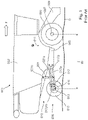
- FIG. 1 shows a schematic side view of a typical layout of a prior art combine harvester.
- FIG. 2 shows a schematic side view of a typical layout of a prior art combine harvester.
- FIG. 3 shows the rear of a combine harvester in ‘pitched forward’ orientation.
- FIG. 4 shows further close-up details of FIG. 3 .
- FIG. 5A shows an embodiment in accordance with aspects of the present application.
- FIGS. 5B and 5C show alternate side views of the embodiment shown in FIG. 5A .
- FIG. 6 shows an embodiment with an extendable wheelbase.
- FIGS. 1 and 2 show a schematic side view of a layout of a combine harvester 001 .
- References to forward, rearward (i.e., backward), left, right, up and down are in relation to the shown arrow F, which defines the normal forward direction of travel of the combine when in use.
- arrow F which defines the normal forward direction of travel of the combine when in use.
- various elements of which only one can be seen may in fact be in pairs—for example, rear wheel(s) 015 .
- the skilled person will readily understand the arrangement of omitted elements.
- Combine harvester 001 has a main body 002 and a chassis 003 to which are mounted a pair of large front wheels/tires 005 on fixed axles 007 .
- a number of harvesting systems such as a thresher, cleaning shoe, etc., which, with a header attached to the feeder house 009 at the front of the combine harvester 001 , give the combine harvester 001 a center of gravity (COG) acting downward in the direction of arrow 011 . Due to the location of the harvesting systems and the header, the COG is normally near the front of the machine, relatively close behind the front wheels 005 .
- COG center of gravity
- the front wheels/tires 005 are typically large, both to cope with the load and also to spread the load on them over as large a surface area as possible so as to limit or minimize soil compaction.
- the wheels/tires may be replaced with tracks.
- a suspension assembly 006 Towards the rear of the machine is a suspension assembly 006 , which typically includes an axle bar 013 on which is mounted steerable rear wheels 015 .
- This axle bar 013 is rotatably mounted on a longitudinal cylindrical pivot mount 017 pm which is fixed to a suspension element 017 .
- the pivot mounting of the axle bar 013 on the pivot mount 017 pm allows compensatory up-and-down movement of the rear wheels 015 on either side: as the left hand wheel goes up or down depending on local ground perturbations, the right hand wheel is allowed to go alternately down or up correspondingly.
- the suspension element 017 is connected to the chassis 003 of the machine by upper and lower suspension swing arms 017 a and 017 b . Also provided is a pair of hydraulic rams 021 with an upper end mounted to the chassis 003 at a pivot point 021 c and a lower end mounted to the lower of the suspension swing arms 017 a at a pivot point 021 s .
- FIG. 1 shows that in general, behind the combine harvester 001 is a relatively ‘open space’ 019 , and thus little to prevent, from a structural point of view, the mounting of suspension element 017 , axle bar 013 and wheels 015 further back.
- the subframe and rear wheels 015 tend to be located closer to the front wheels 005 .
- the wheelbase of the combine harvester 001 which is the longitudinal distance W between the front wheel axle 007 and the nominal rear wheel axle 016 , is therefore usually as short as possible. As can be seen in FIG.
- extension of the hydraulic rams 021 pushes the suspension assembly 006 downwards relative to the combine harvester 001 in the direction of arrow S, which on approximately level ground, such as that ground G shown in FIGS. 1 and 2 , results in the combine harvester 001 pitching forward in the direction of arrow P.
- the hydraulic rams 021 are used to keep the main body 002 and chassis 003 of the combine harvester 001 level when the combine harvester 001 is travelling forward up a slope, so as to maintain the working attitude of the internal harvesting systems.
- FIGS. 3 and 4 show details of a combine harvester embodiment in accordance with the combine harvester 001 described in FIGS. 1 and 2 , with like components numbered in a like manner.
- FIG. 3 shows the rear of a combine harvester in ‘pitched forward’ orientation, with cylinders 021 extended. Further hydraulic pistons 015 hp for steering the rear wheels 015 can be seen mounted on axle bar 013 . Pivot mount 017 pm is shown in FIG. 3 , but would normally be covered by other items that are omitted for clarity. Cylinders 021 may be seen to be joined to each other and to the lower suspension swing arms 017 a by lateral crossbar 017 cb .
- FIG. 4 shows further close-up detail of the suspension element 017 and the axle bar 013 , which is mounted on the longitudinal pivot mount member 017 pm (seen in part represented by dotted lines).
- FIG. 5A shows a partial view of a rear portion of a combine harvester 501 .
- Rear steering axle bar 513 is mounted on cylindrical longitudinal pivot member 517 pm , which protrudes from suspension element 517 , which is connected in turn to the chassis 503 of a combine harvester 501 by means of lower and upper suspension arms 517 a and 517 b .
- Axle bar 513 is able to slide along pivot member 517 pm forward and rearward in the longitudinal direction.
- an actuator 514 having a main body 514 m and a piston 514 p .
- the main body 514 m is attached to the suspension element 517 at flanges 517 f
- the distal end of piston 514 p is attached to the axle bar 513 at flanges 513 f .
- the axle bar 513 can be operably moved forward and rearward along the longitudinal pivot member 517 pm by operation of the actuator 514 , thus altering the wheelbase length of the combine harvester 501 . Further, due to the mounting on the pivot member 517 pm of the axle bar 513 , the axle bar 513 is able to rotate around the longitudinal axis of the cylindrical pivot member 517 pm , as illustrated by double-headed arrow R. This provides a degree of suspension to the system as the wheels 515 (only the right-hand-side wheel shown here but part of both wheel hubs 515 h visible) move up and down in opposition to each other around the pivot point defined by the mounting of the axle bar 513 on the pivot member 517 pm.
- the piston 514 acts to resist the pivoting of the axle bar 513 about the pivot member 517 pm .
- the piston 514 can be mounted to the flanges 517 f and 513 f , or one or other of these flanges, with rubber or silicone bushes. Accordingly, the amount of ‘twist’ that the axle bar 513 is able to undergo around pivot member 517 pm can be both enabled and limited by appropriate selection of such bushes, which may then also act as damping units for the suspension movement.
- the actuator 514 may be mounted on one or both of the suspension member 517 and axle bar 513 by means of pivot mountings allowing movement around a vertical axis.
- the shown actuator 514 may be mounted to the flanges 517 f and 513 f with spherical joints.
- FIGS. 5B and 5C show the same embodiment as in FIG. 5A , but in simplified schematic form and as side views.
- the wheel 515 is omitted from FIGS. 5B and 5C for clarity, with only the hub 515 h on which the wheel 515 is mounted being visible.
- FIG. 5B shows the axle bar 513 at its closest point to suspension member 517 when the actuator 514 is fully retracted.
- FIG. 5C shows the axle bar 513 at its furthest point rearward along longitudinal pivot member 517 pm when the actuator 514 is at its maximum extension, and thus the wheelbase W ( FIG. 1 ) of a combine harvester 501 to which the suspension assembly was fitted would be extended to its maximum. Also visible in FIGS.
- 5B and 5C are parts of lower and upper suspension swing arms 517 a and 517 b , which connect suspension member 517 to the main chassis 503 of the combine in the same way as swing arms 017 a and 017 b of FIGS. 1 through 4 .
- FIG. 6 An advantage of an embodiment of the extendable wheelbase is illustrated in FIG. 6 .
- the combine of FIG. 6 is provided with a longitudinal pitch control system comprising a pitch actuator 621 which is capable of moving the suspension assembly 606 up and down relative to the main body 602 and chassis 603 of the combine 601 .
- a pitch actuator 621 which is capable of moving the suspension assembly 606 up and down relative to the main body 602 and chassis 603 of the combine 601 .
- FIG. 6 shows the longitudinal pitch control system in conjunction with a wheelbase length varying system similar to that shown in FIGS. 5A to 5C , although with only a single swing arm 617 a to which suspension member 617 is fixedly attached, rather than with two swing arms (pivotally attached to the suspension member) as FIGS.
- variable wheelbase system in accordance with aspects of the present application can also increase the operable range of a pitch control system of a combine harvester.
- a combine harvester with a variable length wheelbase A combine harvester with a variable length wheelbase.
- a combine harvester comprising a chassis defining a forward end and a rear end, a feeder house at the forward end of the chassis, a first set of ground-engaging elements supporting the forward end of the chassis, and a second set of ground-engaging elements supporting the rear end of the chassis.
- the second set of ground-engaging elements are configured to move forward and rearward relative to the chassis.
- the combine harvester of Embodiment 15 further comprising a rear axle bar mounted on a longitudinal member protruding rearward from the chassis, wherein the second set of ground-engaging elements is mounted on the rear axle bar.
Abstract
Description
Claims (9)
Applications Claiming Priority (3)
| Application Number | Priority Date | Filing Date | Title |
|---|---|---|---|
| GB1901045.3 | 2019-01-25 | ||
| GBGB1901045.3A GB201901045D0 (en) | 2019-01-25 | 2019-01-25 | Variable wheelbase combine |
| GB1901045 | 2019-01-25 |
Publications (2)
| Publication Number | Publication Date |
|---|---|
| US20200236852A1 US20200236852A1 (en) | 2020-07-30 |
| US11439066B2 true US11439066B2 (en) | 2022-09-13 |
Family
ID=65655867
Family Applications (1)
| Application Number | Title | Priority Date | Filing Date |
|---|---|---|---|
| US16/750,493 Active 2040-11-21 US11439066B2 (en) | 2019-01-25 | 2020-01-23 | Length-variable and pitch-adjustable wheelbase combine |
Country Status (2)
| Country | Link |
|---|---|
| US (1) | US11439066B2 (en) |
| GB (1) | GB201901045D0 (en) |
Families Citing this family (1)
| Publication number | Priority date | Publication date | Assignee | Title |
|---|---|---|---|---|
| US11110771B2 (en) * | 2016-12-07 | 2021-09-07 | Agco Corporation | Wheel axle for a combine harvester |
Citations (17)
| Publication number | Priority date | Publication date | Assignee | Title |
|---|---|---|---|---|
| US2796717A (en) * | 1954-11-01 | 1957-06-25 | Internaltional Harvester Compa | Hillside harvester thresher |
| GB1173920A (en) | 1965-12-30 | 1969-12-10 | Emile Bobard | Self-Propelled Harvester-Thresher Built up from a Conventional Tractor and Harvesting and Threshing Means |
| US4204697A (en) * | 1978-10-27 | 1980-05-27 | David Santerre | Variable wheelbase road truck |
| US4639008A (en) * | 1983-01-07 | 1987-01-27 | Daimler-Benz Aktiengesellschaft | Self-propelling vehicle with two axle units cantilevered together |
| US5368121A (en) | 1993-06-21 | 1994-11-29 | Priefert; William D. | Telescoping tractor frame |
| US6065556A (en) * | 1994-08-30 | 2000-05-23 | Van William Concepts Pty. Ltd. | Variable wheel base vehicle |
| US6416136B1 (en) * | 2000-02-23 | 2002-07-09 | Fred P. Smith | Lightweight, adjustable-height, axle |
| US20040255563A1 (en) | 2003-06-18 | 2004-12-23 | Deere & Company, A Delaware Corporation | Self-propelled harvesting machine |
| US20090206589A1 (en) | 2007-08-06 | 2009-08-20 | Extendquip, Llc | Extendable frame work vehicle having lift member movable in a true vertical fashion |
| US7780197B2 (en) * | 2004-02-11 | 2010-08-24 | Debra Arlene Glad White Trust | Apparatus and method for changing the track of the wheels of a tractor |
| US8348001B2 (en) * | 2008-07-15 | 2013-01-08 | Claas Selbstfahrende Erntemaschinen Gmbh | Agricultural harvesting machine |
| US20130049316A1 (en) | 2011-08-25 | 2013-02-28 | Cnh America Llc | Additional axle for agricultural machine weight redistribution |
| US20140260158A1 (en) * | 2013-03-13 | 2014-09-18 | Agco Corporation | Harvester with extendable rear axle |
| US9226448B2 (en) * | 2006-08-14 | 2016-01-05 | Wright Manufacturing, Inc. | Lawn mower with adjustable rear drive wheels |
| US9308939B2 (en) * | 2007-08-06 | 2016-04-12 | Extendedquip, LLC | Extendable frame work vehicle |
| US20170274704A1 (en) * | 2016-03-22 | 2017-09-28 | Cnh Industrial America Llc | Vehicle with variable caster angle |
| US20210185883A1 (en) * | 2018-08-30 | 2021-06-24 | Ploeger Oxbo Europe B.V. | Self-Propelled Agricultural Machine |
-
2019
- 2019-01-25 GB GBGB1901045.3A patent/GB201901045D0/en not_active Ceased
-
2020
- 2020-01-23 US US16/750,493 patent/US11439066B2/en active Active
Patent Citations (17)
| Publication number | Priority date | Publication date | Assignee | Title |
|---|---|---|---|---|
| US2796717A (en) * | 1954-11-01 | 1957-06-25 | Internaltional Harvester Compa | Hillside harvester thresher |
| GB1173920A (en) | 1965-12-30 | 1969-12-10 | Emile Bobard | Self-Propelled Harvester-Thresher Built up from a Conventional Tractor and Harvesting and Threshing Means |
| US4204697A (en) * | 1978-10-27 | 1980-05-27 | David Santerre | Variable wheelbase road truck |
| US4639008A (en) * | 1983-01-07 | 1987-01-27 | Daimler-Benz Aktiengesellschaft | Self-propelling vehicle with two axle units cantilevered together |
| US5368121A (en) | 1993-06-21 | 1994-11-29 | Priefert; William D. | Telescoping tractor frame |
| US6065556A (en) * | 1994-08-30 | 2000-05-23 | Van William Concepts Pty. Ltd. | Variable wheel base vehicle |
| US6416136B1 (en) * | 2000-02-23 | 2002-07-09 | Fred P. Smith | Lightweight, adjustable-height, axle |
| US20040255563A1 (en) | 2003-06-18 | 2004-12-23 | Deere & Company, A Delaware Corporation | Self-propelled harvesting machine |
| US7780197B2 (en) * | 2004-02-11 | 2010-08-24 | Debra Arlene Glad White Trust | Apparatus and method for changing the track of the wheels of a tractor |
| US9226448B2 (en) * | 2006-08-14 | 2016-01-05 | Wright Manufacturing, Inc. | Lawn mower with adjustable rear drive wheels |
| US20090206589A1 (en) | 2007-08-06 | 2009-08-20 | Extendquip, Llc | Extendable frame work vehicle having lift member movable in a true vertical fashion |
| US9308939B2 (en) * | 2007-08-06 | 2016-04-12 | Extendedquip, LLC | Extendable frame work vehicle |
| US8348001B2 (en) * | 2008-07-15 | 2013-01-08 | Claas Selbstfahrende Erntemaschinen Gmbh | Agricultural harvesting machine |
| US20130049316A1 (en) | 2011-08-25 | 2013-02-28 | Cnh America Llc | Additional axle for agricultural machine weight redistribution |
| US20140260158A1 (en) * | 2013-03-13 | 2014-09-18 | Agco Corporation | Harvester with extendable rear axle |
| US20170274704A1 (en) * | 2016-03-22 | 2017-09-28 | Cnh Industrial America Llc | Vehicle with variable caster angle |
| US20210185883A1 (en) * | 2018-08-30 | 2021-06-24 | Ploeger Oxbo Europe B.V. | Self-Propelled Agricultural Machine |
Non-Patent Citations (1)
| Title |
|---|
| UK Intellectual Property Office, Search Report for UK Priority Application No. GB1901045.3, dated Jul. 18, 2019. |
Also Published As
| Publication number | Publication date |
|---|---|
| US20200236852A1 (en) | 2020-07-30 |
| GB201901045D0 (en) | 2019-03-13 |
Similar Documents
| Publication | Publication Date | Title |
|---|---|---|
| US8020648B2 (en) | Windrower tractor with rear wheel suspension | |
| US7866671B2 (en) | Automatic leveling vehicle | |
| US6406043B1 (en) | Suspension and steering system for a vehicle | |
| EP4228909A1 (en) | Suspension system | |
| US11571939B2 (en) | Suspension system | |
| EP3568308B1 (en) | Vehicle suspension system | |
| US20230337563A1 (en) | Mounting Assembly for a Steerable Wheel with Variable Track Width | |
| US6488114B1 (en) | Grain cart | |
| US6843046B2 (en) | Support wheel assembly for an agricultural implement on an agricultural machine | |
| EP0691258B1 (en) | Steering mechanism for compact tractors | |
| US5476276A (en) | Compound steering mechanism with alternate chassis mounts | |
| US6402170B1 (en) | Enhanced steering mechanism for utility vehicles | |
| US11439066B2 (en) | Length-variable and pitch-adjustable wheelbase combine | |
| US5088570A (en) | Steerable rear dual axle system for large trucks | |
| US4418932A (en) | Front axle suspension system for a vehicle chassis | |
| US5322309A (en) | Oscillation stops for tractors with compound steering mechanism | |
| AU741618B2 (en) | Front axle suspension | |
| GB2424630A (en) | Vehicle with adjustable track width | |
| US8056911B2 (en) | Compound steering mechanism | |
| EP2329969B1 (en) | Front axle assembly for a vehicle | |
| US11511581B1 (en) | Suspension system | |
| JP2528328B2 (en) | Rear wheel suspension | |
| JP2021098475A (en) | Work machine | |
| DE69832762T2 (en) | Steering angle correction mechanism | |
| GB2397811A (en) | Steering, suspension and wheel track location mechanism for variable track vehicle |
Legal Events
| Date | Code | Title | Description |
|---|---|---|---|
| AS | Assignment |
Owner name: AGCO INTERNATIONAL GMBH, SWITZERLAND Free format text: ASSIGNMENT OF ASSIGNORS INTEREST;ASSIGNOR:ALESSIO, ADDIFETTI;REEL/FRAME:051599/0151 Effective date: 20190125 |
|
| FEPP | Fee payment procedure |
Free format text: ENTITY STATUS SET TO UNDISCOUNTED (ORIGINAL EVENT CODE: BIG.); ENTITY STATUS OF PATENT OWNER: LARGE ENTITY |
|
| AS | Assignment |
Owner name: AGCO INTERNATIONAL GMBH, SWITZERLAND Free format text: ASSIGNMENT OF ASSIGNORS INTEREST;ASSIGNOR:ADDIFETTI, ALESSIO;REEL/FRAME:052269/0851 Effective date: 20190125 |
|
| STPP | Information on status: patent application and granting procedure in general |
Free format text: APPLICATION DISPATCHED FROM PREEXAM, NOT YET DOCKETED |
|
| STPP | Information on status: patent application and granting procedure in general |
Free format text: DOCKETED NEW CASE - READY FOR EXAMINATION |
|
| STPP | Information on status: patent application and granting procedure in general |
Free format text: NON FINAL ACTION MAILED |
|
| STPP | Information on status: patent application and granting procedure in general |
Free format text: RESPONSE TO NON-FINAL OFFICE ACTION ENTERED AND FORWARDED TO EXAMINER |
|
| STPP | Information on status: patent application and granting procedure in general |
Free format text: PUBLICATIONS -- ISSUE FEE PAYMENT VERIFIED |
|
| STCF | Information on status: patent grant |
Free format text: PATENTED CASE |