US11433769B2 - Motor driving apparatus and laundry treating apparatus including the same - Google Patents
Motor driving apparatus and laundry treating apparatus including the same Download PDFInfo
- Publication number
- US11433769B2 US11433769B2 US16/907,508 US202016907508A US11433769B2 US 11433769 B2 US11433769 B2 US 11433769B2 US 202016907508 A US202016907508 A US 202016907508A US 11433769 B2 US11433769 B2 US 11433769B2
- Authority
- US
- United States
- Prior art keywords
- power generation
- switches
- current
- generation braking
- axis current
- Prior art date
- Legal status (The legal status is an assumption and is not a legal conclusion. Google has not performed a legal analysis and makes no representation as to the accuracy of the status listed.)
- Active, expires
Links
Images


Classifications
-
- D—TEXTILES; PAPER
- D06—TREATMENT OF TEXTILES OR THE LIKE; LAUNDERING; FLEXIBLE MATERIALS NOT OTHERWISE PROVIDED FOR
- D06F—LAUNDERING, DRYING, IRONING, PRESSING OR FOLDING TEXTILE ARTICLES
- D06F37/00—Details specific to washing machines covered by groups D06F21/00 - D06F25/00
- D06F37/30—Driving arrangements
- D06F37/40—Driving arrangements for driving the receptacle and an agitator or impeller, e.g. alternatively
-
- B—PERFORMING OPERATIONS; TRANSPORTING
- B60—VEHICLES IN GENERAL
- B60L—PROPULSION OF ELECTRICALLY-PROPELLED VEHICLES; SUPPLYING ELECTRIC POWER FOR AUXILIARY EQUIPMENT OF ELECTRICALLY-PROPELLED VEHICLES; ELECTRODYNAMIC BRAKE SYSTEMS FOR VEHICLES IN GENERAL; MAGNETIC SUSPENSION OR LEVITATION FOR VEHICLES; MONITORING OPERATING VARIABLES OF ELECTRICALLY-PROPELLED VEHICLES; ELECTRIC SAFETY DEVICES FOR ELECTRICALLY-PROPELLED VEHICLES
- B60L3/00—Electric devices on electrically-propelled vehicles for safety purposes; Monitoring operating variables, e.g. speed, deceleration or energy consumption
- B60L3/0023—Detecting, eliminating, remedying or compensating for drive train abnormalities, e.g. failures within the drive train
-
- H—ELECTRICITY
- H02—GENERATION; CONVERSION OR DISTRIBUTION OF ELECTRIC POWER
- H02P—CONTROL OR REGULATION OF ELECTRIC MOTORS, ELECTRIC GENERATORS OR DYNAMO-ELECTRIC CONVERTERS; CONTROLLING TRANSFORMERS, REACTORS OR CHOKE COILS
- H02P21/00—Arrangements or methods for the control of electric machines by vector control, e.g. by control of field orientation
- H02P21/22—Current control, e.g. using a current control loop
-
- B—PERFORMING OPERATIONS; TRANSPORTING
- B60—VEHICLES IN GENERAL
- B60L—PROPULSION OF ELECTRICALLY-PROPELLED VEHICLES; SUPPLYING ELECTRIC POWER FOR AUXILIARY EQUIPMENT OF ELECTRICALLY-PROPELLED VEHICLES; ELECTRODYNAMIC BRAKE SYSTEMS FOR VEHICLES IN GENERAL; MAGNETIC SUSPENSION OR LEVITATION FOR VEHICLES; MONITORING OPERATING VARIABLES OF ELECTRICALLY-PROPELLED VEHICLES; ELECTRIC SAFETY DEVICES FOR ELECTRICALLY-PROPELLED VEHICLES
- B60L50/00—Electric propulsion with power supplied within the vehicle
- B60L50/50—Electric propulsion with power supplied within the vehicle using propulsion power supplied by batteries or fuel cells
- B60L50/52—Electric propulsion with power supplied within the vehicle using propulsion power supplied by batteries or fuel cells characterised by DC-motors
-
- B—PERFORMING OPERATIONS; TRANSPORTING
- B60—VEHICLES IN GENERAL
- B60L—PROPULSION OF ELECTRICALLY-PROPELLED VEHICLES; SUPPLYING ELECTRIC POWER FOR AUXILIARY EQUIPMENT OF ELECTRICALLY-PROPELLED VEHICLES; ELECTRODYNAMIC BRAKE SYSTEMS FOR VEHICLES IN GENERAL; MAGNETIC SUSPENSION OR LEVITATION FOR VEHICLES; MONITORING OPERATING VARIABLES OF ELECTRICALLY-PROPELLED VEHICLES; ELECTRIC SAFETY DEVICES FOR ELECTRICALLY-PROPELLED VEHICLES
- B60L7/00—Electrodynamic brake systems for vehicles in general
- B60L7/10—Dynamic electric regenerative braking
-
- D—TEXTILES; PAPER
- D06—TREATMENT OF TEXTILES OR THE LIKE; LAUNDERING; FLEXIBLE MATERIALS NOT OTHERWISE PROVIDED FOR
- D06F—LAUNDERING, DRYING, IRONING, PRESSING OR FOLDING TEXTILE ARTICLES
- D06F34/00—Details of control systems for washing machines, washer-dryers or laundry dryers
- D06F34/10—Power supply arrangements, e.g. stand-by circuits
-
- D—TEXTILES; PAPER
- D06—TREATMENT OF TEXTILES OR THE LIKE; LAUNDERING; FLEXIBLE MATERIALS NOT OTHERWISE PROVIDED FOR
- D06F—LAUNDERING, DRYING, IRONING, PRESSING OR FOLDING TEXTILE ARTICLES
- D06F37/00—Details specific to washing machines covered by groups D06F21/00 - D06F25/00
- D06F37/30—Driving arrangements
- D06F37/304—Arrangements or adaptations of electric motors
-
- H—ELECTRICITY
- H02—GENERATION; CONVERSION OR DISTRIBUTION OF ELECTRIC POWER
- H02P—CONTROL OR REGULATION OF ELECTRIC MOTORS, ELECTRIC GENERATORS OR DYNAMO-ELECTRIC CONVERTERS; CONTROLLING TRANSFORMERS, REACTORS OR CHOKE COILS
- H02P21/00—Arrangements or methods for the control of electric machines by vector control, e.g. by control of field orientation
- H02P21/36—Arrangements for braking or slowing; Four quadrant control
-
- H—ELECTRICITY
- H02—GENERATION; CONVERSION OR DISTRIBUTION OF ELECTRIC POWER
- H02P—CONTROL OR REGULATION OF ELECTRIC MOTORS, ELECTRIC GENERATORS OR DYNAMO-ELECTRIC CONVERTERS; CONTROLLING TRANSFORMERS, REACTORS OR CHOKE COILS
- H02P27/00—Arrangements or methods for the control of AC motors characterised by the kind of supply voltage
- H02P27/04—Arrangements or methods for the control of AC motors characterised by the kind of supply voltage using variable-frequency supply voltage, e.g. inverter or converter supply voltage
- H02P27/06—Arrangements or methods for the control of AC motors characterised by the kind of supply voltage using variable-frequency supply voltage, e.g. inverter or converter supply voltage using DC to AC converters or inverters
-
- H—ELECTRICITY
- H02—GENERATION; CONVERSION OR DISTRIBUTION OF ELECTRIC POWER
- H02P—CONTROL OR REGULATION OF ELECTRIC MOTORS, ELECTRIC GENERATORS OR DYNAMO-ELECTRIC CONVERTERS; CONTROLLING TRANSFORMERS, REACTORS OR CHOKE COILS
- H02P6/00—Arrangements for controlling synchronous motors or other dynamo-electric motors using electronic commutation dependent on the rotor position; Electronic commutators therefor
- H02P6/14—Electronic commutators
- H02P6/16—Circuit arrangements for detecting position
- H02P6/18—Circuit arrangements for detecting position without separate position detecting elements
-
- D—TEXTILES; PAPER
- D06—TREATMENT OF TEXTILES OR THE LIKE; LAUNDERING; FLEXIBLE MATERIALS NOT OTHERWISE PROVIDED FOR
- D06F—LAUNDERING, DRYING, IRONING, PRESSING OR FOLDING TEXTILE ARTICLES
- D06F2103/00—Parameters monitored or detected for the control of domestic laundry washing machines, washer-dryers or laundry dryers
- D06F2103/38—Time, e.g. duration
-
- D—TEXTILES; PAPER
- D06—TREATMENT OF TEXTILES OR THE LIKE; LAUNDERING; FLEXIBLE MATERIALS NOT OTHERWISE PROVIDED FOR
- D06F—LAUNDERING, DRYING, IRONING, PRESSING OR FOLDING TEXTILE ARTICLES
- D06F2103/00—Parameters monitored or detected for the control of domestic laundry washing machines, washer-dryers or laundry dryers
- D06F2103/44—Current or voltage
- D06F2103/46—Current or voltage of the motor driving the drum
-
- D—TEXTILES; PAPER
- D06—TREATMENT OF TEXTILES OR THE LIKE; LAUNDERING; FLEXIBLE MATERIALS NOT OTHERWISE PROVIDED FOR
- D06F—LAUNDERING, DRYING, IRONING, PRESSING OR FOLDING TEXTILE ARTICLES
- D06F2105/00—Systems or parameters controlled or affected by the control systems of washing machines, washer-dryers or laundry dryers
- D06F2105/46—Drum speed; Actuation of motors, e.g. starting or interrupting
- D06F2105/48—Drum speed
-
- D—TEXTILES; PAPER
- D06—TREATMENT OF TEXTILES OR THE LIKE; LAUNDERING; FLEXIBLE MATERIALS NOT OTHERWISE PROVIDED FOR
- D06F—LAUNDERING, DRYING, IRONING, PRESSING OR FOLDING TEXTILE ARTICLES
- D06F25/00—Washing machines with receptacles, e.g. perforated, having a rotary movement, e.g. oscillatory movement, the receptacle serving both for washing and for centrifugally separating water from the laundry and having further drying means, e.g. using hot air
-
- Y—GENERAL TAGGING OF NEW TECHNOLOGICAL DEVELOPMENTS; GENERAL TAGGING OF CROSS-SECTIONAL TECHNOLOGIES SPANNING OVER SEVERAL SECTIONS OF THE IPC; TECHNICAL SUBJECTS COVERED BY FORMER USPC CROSS-REFERENCE ART COLLECTIONS [XRACs] AND DIGESTS
- Y02—TECHNOLOGIES OR APPLICATIONS FOR MITIGATION OR ADAPTATION AGAINST CLIMATE CHANGE
- Y02T—CLIMATE CHANGE MITIGATION TECHNOLOGIES RELATED TO TRANSPORTATION
- Y02T10/00—Road transport of goods or passengers
- Y02T10/60—Other road transportation technologies with climate change mitigation effect
- Y02T10/70—Energy storage systems for electromobility, e.g. batteries
Definitions
- the present disclosure relates to a motor driving apparatus for performing power generation braking and a home appliance including the same.
- a laundry treatment apparatus is an apparatus for treating laundry through several actions, such as washing, dehydration and/or dry.
- a motor driving apparatus for driving a motor including a rotor performing a rotation movement and a stator on which a coil is wound may be divided into a motor driving apparatus using a sensor method using a sensor and a motor driving apparatus using a sensorless method not using a sensor.
- the motor driving apparatus using the sensorless method is a lot used due to a reduced manufacturing cost.
- research for efficiently driving the motor is carried out.
- a direct drive method of directly transmitting the turning force of the motor to a pulsator or drum through a gear unit has been developed as a method of efficiently driving the motor.
- the rotation speed of the motor is also significantly increased for the purpose of dehydration performance improvements and rapid dehydration.
- a clothing treatment apparatus based on the direct drive method using the gear unit includes a coupling member between a rotor bush to which the rotation shaft of the motor has been coupled and the gear unit.
- a given gap is formed between the rotor bush and the coupling member or between the gear unit and the coupling member.
- noise may occur because the rotor bush and the coupling member collide against each other or the coupling member and the gear unit collide against each other.
- a difference between inertia occurring in the rotor bush and inertia occurring in the pulsator or the drum is increased as the gear ratio of the gear unit is increased in order to reduce power consumption of a washing machine. Accordingly, noise attributable to a collision between the rotor bush and the coupling member and a collision or between the coupling member and the gear unit may be increased. Such noise is further increased as the RPM of the motor is increased.
- this applicant proposed braking logic illustrating in FIG. 1 in order to reduce noise occurring upon motor braking.
- the braking logic illustrated in FIG. 1 is described below, and includes spare braking, intermediate braking, and power generation braking.
- the spare braking means that the rotation speed of the motor is naturally decelerated by maintaining, in a full off state, a plurality of upper switches and a plurality of lower switches included in an inverter unit for a given time.
- the power generation braking means that the rotation speed of the motor is artificially decelerated by maintaining, in the full off state, the plurality of upper switches included in the inverter unit and maintaining, in a full on state, the plurality of lower switches included in the inverter unit.
- intermediate braking means that the upper switches of the inverter unit are maintained in the full off state and the duty ratio of the lower switches is linearly increased.
- the power generation braking can be entered in the state in which the braking power slowly increases. Accordingly, noise occurring when the spare braking switches to the power generation braking is reduced compared to a case not using the intermediate braking.
- braking noise occurs at power generation braking timing because an instant change of current occurring upon switching from the intermediate braking to the power generation braking is transmitted to the apparatus. Accordingly, there is a need to develop a technology capable of effectively reducing noise occurring at power generation braking timing.
- the present disclosure provides a motor driving apparatus capable of minimizing noise occurring at power generation braking timing of a motor and a clothing treatment apparatus including the motor driving apparatus.
- the present disclosure provides a motor driving apparatus capable of preventing an element directly or indirectly coupled to a motor from being damaged upon power generation braking of the motor and a clothing treatment apparatus including the motor driving apparatus.
- the present disclosure provides a motor driving apparatus capable of preventing noise occurring in an apparatus including a motor and also increasing the safety of the apparatus including the motor when power generation braking of the motor is performed, and a clothing treatment apparatus including the motor driving apparatus
- a motor driving apparatus an inverter unit including a plurality of upper switches and a plurality of lower switches and configured to output AC power to a motor by a switching operation and a processor configured to control the inverter unit to perform power generation braking by maintaining the plurality of upper switches in a full off state and maintain the plurality of lower switches in a full on state.
- phase currents flowing into the plurality of upper switches and the plurality of lower switches prior to the power generation braking are complementarily switched.
- the processor may be configured to set a d-axis current to ⁇ 2 A to ⁇ 3 A and a q-axis current to 0 A in a primary current control step when the n is 0 (zero).
- the processor may be configured to set, as an initial current value in power generation braking in a next degree, a current value detected within 10 ms from the (n+1)-th power generation braking timing.
- the processor may be configured to perform spare braking for maintaining the pluralities of upper switches and lower switches of the inverter unit in the full off state and then perform the current control step and to perform the power generation braking after performing the current control step.
- the processor may be configured to substantially identically set sizes of phase currents flowing into the plurality of upper switches and the plurality of lower switches in the current control step.
- the current control step may be performed for 100 ms.
- the processor may be configured to calculate a d-axis current value (I d # ) and a q-axis current value (I q # ) using an equation below in the current control step.
- I d # ( I ds /10)*Cnt
- I q # ( I dq /10)*Cnt
- I ds an initial d-axis current value in a previously-generated power generation braking step
- I dq an initial q-axis current value in a previously-generated power generation braking step.
- a clothing treatment apparatus including the motor driving apparatus having such a configuration may further include a transmission system for changing torque generated by the motor.
- the transmission system may includes a first shaft unit connected to a pulsator, a bush provided in a rotor of the motor, a second shaft unit inserted into the bush, a third shaft unit connected to a tub of the clothing treatment apparatus, a gear unit positioned between the first shaft unit and the second shaft unit to change torque generated by the motor, and a coupling positioned between the rotor and the third shaft unit in a way to be movable up and down.
- the motor driving apparatus can reduce each of a d-axis current change amount and q-axis current change amount at power generation braking timing within 0.1 A by controlling a dq-axis current before performing power generation braking.
- FIG. 1 is a graph illustrating an operating state of the upper and lower switches of an inverter in braking logic according to a conventional technology.
- FIG. 2 is a graph illustrating a dq-axis current at braking timing in the braking logic according to a conventional technology.
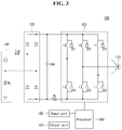
- FIG. 3 is a circuit diagram of a motor driving apparatus according to an embodiment of the present disclosure.
- FIG. 4 is a block diagram illustrating the elements of a washing machine including a gear unit.
- FIG. 5 is a concept view illustrating parts connected to a gear unit.
- FIG. 6 is a flowchart illustrating a method of controlling the motor driving apparatus according to an embodiment of the present disclosure.
- FIGS. 7A and 7B are graphs illustrating an operating state of the upper and lower switches of an inverter in braking logic according to an embodiment of the present disclosure.
- FIG. 8 is a graph illustrating a dq-axis current at braking timing in the braking logic according to an embodiment of the present disclosure.
- terms such as a first and a second, may be used to describe various elements, but the elements may not be restricted by the terms. The terms are used to only distinguish one element from the other element.
- a first element may be named a second element without departing from the scope of rights of the present disclosure.
- a second element may be named a first element.
- the motor driving apparatus 100 may include a motor unit 110 , an inverter unit 120 , a rectification unit 130 , an input power unit 140 , an input unit 150 , an output unit 160 and a processor 180 .
- the motor unit 110 may be a motor for rotating the pulsator of a washing machine. Furthermore, the motor unit 110 may be a motor for rotating the drum of a washing machine. For example, the motor unit 110 may be a 3-phase motor.
- the rectification unit 130 may receive an input power source from the input power unit 140 , may rectify the received input power source, and may convert the power source in a form of a DC voltage. That is, the rectification unit 130 may output a DC voltage having a constant level.
- a DC-stage capacitor Cap may be connected to both ends of the rectification unit 130 .
- the DC-stage capacitor Cap may smooth and store the DC voltage output by the rectification unit 130 .
- the DC-stage capacitor Cap may be a DC link capacitor.
- the DC voltage smoothed by the DC link capacitor as described above may be transmitted to the inverter unit 120 .
- the inverter unit 120 may include a plurality of switches. More specifically, if the motor unit 110 is a 3-phase motor, the inverter unit 120 may include a switch pair corresponding to each phase.
- the inverter unit 120 may include first to sixth switches S 1 , S 2 , S 3 , S 4 , S 5 , and S 6 .
- a MOSFET or an insulated gate bipolar transistor (IGBT) may be used as the switch.
- the first to third switches S 1 , S 2 , and S 3 may have collectors each coupled to one end of the DC link capacitor Cap.
- the fourth to sixth switches S 4 , S 5 and S 6 may have emitters each coupled to the other end of the DC link capacitor.
- the plurality of switches included in the inverter unit may be classified into upper switches and lower switches depending on their installation locations.
- the first to third switches S, S 2 , and S 3 may be defined as the upper switches, and the fourth to sixth switches S 4 , S 5 and S 6 may be defined as the lower switches.
- the inverter unit 120 may convert, into 3-phase AC power, the DC voltage received from the DC link capacitor, and may apply the 3-phase AC power to the motor unit 110 .
- the inverter unit 120 may be defined as a 3-level inverter.
- a shunt resistor R S for detecting the phase current of the motor unit 110 may be provided between the inverter unit 120 and the DC link capacitor Cap. However, the shunt resistor may be omitted.
- a reactor L RE for stabilizing an impact on a transformer attributable to an inrush current, which may occur in the rectification unit 130 when the input power source is applied to the rectification unit 130 , may be provided between the rectification unit 130 and the input power unit 140 .
- the reactor may be formed as an inductor and may be omitted.
- the processor 180 may output, to the inverter unit 120 , an inverter control signal to control the 3-level inverter.
- the inverter control signal may be a pulse width modulation (PWM) control signal.
- PWM pulse width modulation
- the PWM control signal may include a control signal for adjusting the duty ratio of the switches included in the inverter unit.
- the duty ratio means an on duty ratio, that is, a ratio of time during which the state of a switch is an on state in a given time interval. Accordingly, a maximum value of the duty ratio is 100%, and a minimum value of the duty ratio is 0%.
- the setting of the duty ratio of the switch as a maximum value is defined as the full on mode of the switch.
- the setting of the duty ratio of the switch as a minimum value is defined as the full off mode of the switch.
- the time for which the state of the switch is maintained in an on state and the time for which the state of the switch is maintained in an off state during one cycle of the switch may be changed based on the duty ratio of the switch set by the processor 180 .
- the state in which the state of the switch continues to be maintained in the on state during one cycle of the switch is defined as the full on state of the switch.
- the state in which the state of the switch continues to be maintained in the off state during one cycle of the switch is defined as the full off state of the switch.
- the processor 180 may further include a memory (not illustrated) for storing data to control an inverter controller.
- the input unit 150 may receive user inputs related to an operation of the motor unit 110 and an operation of the inverter unit 120 . When a user input is received, the input unit may transmit, to the processor 180 , a signal corresponding to the received user input.
- the output unit 160 may receive a given signal from the processor 180 and operate based on the received signal.
- the output unit 160 may include output elements, such as a light-emitting diode (LED), an OLED, a buzzer.
- LED light-emitting diode
- OLED organic light-emitting diode
- buzzer a buzzer
- FIG. 4 illustrates a washing machine using a pulsator method, but the present disclosure is not limited thereto.
- FIG. 4 may be applied to a washing machine using a drum method.
- a gear unit 203 may be positioned between a pulsator 201 and an element included in a motor.
- a first shaft unit 202 may be connected to the center of the pulsator 201 . Accordingly, the pulsator 201 and the first shaft unit 202 may be rotated together.
- the motor unit 110 may include a rotor 206 , a stator 210 and a housing 211 .
- the rotor 206 may be rotated by a magnetic field generated by the stator 210 .
- a bush 205 may be positioned at the center of the rotor 206 .
- a second shaft unit 204 may be inserted into the bush 205 . Accordingly, the rotor 206 , the bush 205 and the second shaft unit 204 may be rotated together.
- the gear unit 203 may be positioned between the second shaft unit 204 and the first shaft unit 202 .
- the gear unit 203 may be connected to the first shaft unit 202 and the second shaft unit 204 .
- the gear unit 203 may be configured to be engaged with saw-toothed parts (not illustrated) formed in the insides of the first shaft unit 202 and the second shaft unit 204 .
- the first shaft unit 202 , the gear unit 203 and the second shaft unit 204 may be disposed in such a way to be rotated within the third shaft unit 208 .
- a tub 209 may be coupled to the top of a third shaft unit 208 .
- the bottom of the third shaft unit 208 may be spaced apart from the top of the bush 205 at a given interval.
- first shaft unit and the third shaft unit 202 and 204 may be defined as a washing shaft.
- the third shaft unit 208 may be defined as a dehydration shaft.
- a coupling 207 may be positioned between the third shaft unit 208 and the bush 205 .
- the coupling 207 may be positioned in a way to be movable up and down.
- the coupling 207 may move up and down and restrict the third shaft unit 208 so that only the first and second shaft units are rotated, or may move down and transmit the turning force of the rotor 206 to the first to third shaft units so that the first shaft unit to the third shaft unit are rotated at the same time.
- a gap having a given interval is formed between the bush 205 and the coupling 207 .
- a relative speed difference between the third shaft unit 208 and the second shaft unit 204 occurs due to a torque change.
- the contact state of the coupling 207 with the bush 205 or the third shaft unit 208 is changed due to the speed difference.
- the inertia of the first shaft unit and second shaft unit defined as the washing shaft is smaller than the inertia of the third shaft unit defined as the dehydration shaft by the application of the gear unit 203 . Accordingly, upon braking of the motor, a collision occurs between the coupling 207 and the bush 205 , and noise occurs due to the collision.
- a magnetic field is generated from the stator in response to a power source applied to the stator 210 .
- the rotor 206 is rotated by the magnetic field of the stator 210 .
- the turning force of the rotor 206 is transmitted to the bush 205 .
- the turning force transmitted to the bush is transmitted to the second shaft unit 204 .
- the coupling 207 moves up and down and thus the protruded parts of the coupling are discharged from grooves formed in the bush 205 . Accordingly, the turning force of the rotor 206 is transmitted to only the second shaft unit 204 .
- the RPM of the second shaft unit 204 is decelerated to a given gear ratio in the gear unit 203 .
- the first shaft unit 202 and the pulsator 201 perform a washing cycle while being rotated at a low speed of the decelerated RPM.
- a rinse cycle is performed.
- a dehydration cycle is performed in order to minimize moisture included in laundry.
- the coupling 207 moves down. Accordingly, the protruded parts of the coupling 207 are inserted into the grooves formed in the bush 205 . That is, one side of the coupling 207 and one side of the bush 205 are engaged.
- the turning force of the rotor 206 is transmitted to all of the first to third shaft units. Accordingly, the pulsator 201 connected to the first and second shaft units and the tub 209 connected to the third shaft unit are simultaneously rotated at a high speed.
- the laundry is washed through the washing cycle, the rinse cycle and the dehydration cycle. Recently, a dry cycle is separately added after the dehydration cycle.
- the processor 180 of the motor driving apparatus performs spare braking for a given time.
- the processor 180 When time required for the spare braking elapses, the processor 180 set a count (Cnt) to 1, calculates an initial current value of power generation braking and then performs a current control step based on the calculated initial current value.
- the current control step means that the initial current value detected in power generation braking in a previous degree is set as an initial current value of power generation braking in a current degree and a dq-axis current amount is controlled based on the set initial current value.
- phase currents flowing into the plurality of upper switches and the plurality of lower switches of the inverter unit are complementarily switched.
- “complementary switching” means that the on/off of the upper switches and the on/off of the lower switches are switched in a manner opposite to each other.
- the sizes of the phase current of the upper switches and the phase current of the lower switches are substantially identical, the upper switches become off, and the lower switches become on.
- the power generation braking is entered in the state in which the upper switches have become off and the lower switches have become on.
- FIG. 6 illustrates that the duty ratios of phase currents applied to the upper switches and lower switches in the current control step are identical with the duty ratios of phase currents applied to the upper switches and lower switches upon normal operation. However, the duty ratios of phase currents applied to the upper switches and lower switches in the current control step may be different from the duty ratios of phase currents applied to the upper switches and lower switches upon normal operation.
- the duty ratios of phase currents applied to the upper switches and lower switches in the current control step may be increased over time.
- the duty ratios of phase currents applied to the upper switches and lower switches in the current control step may be increased or decreased over time.
- the duty ratios of phase currents applied to the upper switches and lower switches in the current control step may be changed in various forms.
- an A-phase current may be linearly increased from 0 (zero) to an initial current of the power generation braking.
- a d-axis current value (I d # ) and a q-axis current value (I q # ) may be calculated again in a given time unit (e.g., 10 ms).
- the current control step may be performed for a total of 100 ms.
- a total time for which the current control step is performed may be variously changed.
- a time unit by which the d-axis current value (I d # ) and the q-axis current value (I q # ) are calculated again may be variously changed.
- the current control step may be performed for a total of 150 ms or for a total of 200 s. In some embodiments, the current control step may be performed for a total of 80 ms.
- the time unit by which the d-axis current value (I d # ) and the q-axis current value (I q # ) are calculated again may be 2.5 ms or 5 ms.
- the total time for which the current control step is performed and the time unit by which the d-axis current value (I d # ) and the q-axis current value (I q # ) are calculated again may be changed, if necessary.
- the d-axis current value (I d # ) and the q-axis current value (I q # ) may be calculated using an equation below.
- I d # ( I ds /10)*Cnt
- I q # ( I dq /10)*Cnt
- Cnt 1 to 10. Cnt increases by one per 10 ms starting from 1.
- I ds an initial d-axis current value in a previously-generated power generation braking step
- I dq an initial q-axis current value in a previously-generated power generation braking step
- a d-axis current may be set to ⁇ 2 A to ⁇ 3 A, and a q-axis current may be set to 0 A.
- a current value detected within 10 ms from power generation braking timing in a previous degree may be used as the values of I ds and I dq .
- the processor 180 When a set time (e.g., 100 ms) elapses, the processor 180 performs the power generation braking.
- a set time e.g., 100 ms
- the power generation braking means that the rotation speed of the motor is artificially decelerated by maintaining the state of the plurality of upper switches of the inverter unit in the full off state and maintaining the plurality of lower switches of the inverter unit in the full on state.
- the motor driving apparatus detects a dq-axis current upon previous power generation braking and calculates a dq-axis current amount in a present current control step based on the detected dq-axis current, and thus can reduce a change in the dq-axis current regardless of an operation condition when entering power generation braking.
- each of a d-axis current change amount and a q-axis current change amount at power generation braking timing can be minimized.
- each of a d-axis current change amount and a q-axis current change amount at power generation braking timing may be within 0.1 A.
Landscapes
- Engineering & Computer Science (AREA)
- Power Engineering (AREA)
- Textile Engineering (AREA)
- Transportation (AREA)
- Mechanical Engineering (AREA)
- Life Sciences & Earth Sciences (AREA)
- Sustainable Development (AREA)
- Sustainable Energy (AREA)
- Control Of Washing Machine And Dryer (AREA)
- Main Body Construction Of Washing Machines And Laundry Dryers (AREA)
- Stopping Of Electric Motors (AREA)
Abstract
Description
I d #=(I ds/10)*Cnt
I q #=(I dq/10)*Cnt
I d #=(I ds/10)*Cnt
I q #=(I dq/10)*Cnt
Claims (20)
Applications Claiming Priority (2)
| Application Number | Priority Date | Filing Date | Title |
|---|---|---|---|
| KR10-2019-0086431 | 2019-07-17 | ||
| KR1020190086431A KR102674034B1 (en) | 2019-07-17 | 2019-07-17 | Motor driving apparatus and laundry treating appratus with the same |
Publications (2)
| Publication Number | Publication Date |
|---|---|
| US20210016665A1 US20210016665A1 (en) | 2021-01-21 |
| US11433769B2 true US11433769B2 (en) | 2022-09-06 |
Family
ID=74238190
Family Applications (1)
| Application Number | Title | Priority Date | Filing Date |
|---|---|---|---|
| US16/907,508 Active 2041-03-18 US11433769B2 (en) | 2019-07-17 | 2020-06-22 | Motor driving apparatus and laundry treating apparatus including the same |
Country Status (2)
| Country | Link |
|---|---|
| US (1) | US11433769B2 (en) |
| KR (1) | KR102674034B1 (en) |
Citations (2)
| Publication number | Priority date | Publication date | Assignee | Title |
|---|---|---|---|---|
| US20050160771A1 (en) * | 2001-12-13 | 2005-07-28 | Kabushiki Kaisha Toshiba | Inverter for washing machine and inverter of washing machine-dryer |
| US20080297099A1 (en) * | 2007-05-29 | 2008-12-04 | Kabushiki Kaisha Toshiba | Motor controller, washing machine, and motor control method |
Family Cites Families (5)
| Publication number | Priority date | Publication date | Assignee | Title |
|---|---|---|---|---|
| JP4592712B2 (en) | 2007-01-29 | 2010-12-08 | 株式会社日立製作所 | Motor control device |
| JP5252229B2 (en) | 2009-10-02 | 2013-07-31 | アイシン・エィ・ダブリュ株式会社 | Control device for motor drive device |
| JP6470913B2 (en) * | 2014-04-28 | 2019-02-13 | 日立オートモティブシステムズ株式会社 | Motor drive system |
| KR102502161B1 (en) * | 2017-11-29 | 2023-02-21 | 엘지전자 주식회사 | Apparatus for controlling motor, system for controlling motor and mehtod for controlling motor |
| KR20190063252A (en) * | 2017-11-29 | 2019-06-07 | 엘지전자 주식회사 | Laundry treating appratus and controlling method thereof |
-
2019
- 2019-07-17 KR KR1020190086431A patent/KR102674034B1/en active Active
-
2020
- 2020-06-22 US US16/907,508 patent/US11433769B2/en active Active
Patent Citations (2)
| Publication number | Priority date | Publication date | Assignee | Title |
|---|---|---|---|---|
| US20050160771A1 (en) * | 2001-12-13 | 2005-07-28 | Kabushiki Kaisha Toshiba | Inverter for washing machine and inverter of washing machine-dryer |
| US20080297099A1 (en) * | 2007-05-29 | 2008-12-04 | Kabushiki Kaisha Toshiba | Motor controller, washing machine, and motor control method |
Also Published As
| Publication number | Publication date |
|---|---|
| KR102674034B1 (en) | 2024-06-12 |
| KR20210009643A (en) | 2021-01-27 |
| US20210016665A1 (en) | 2021-01-21 |
Similar Documents
| Publication | Publication Date | Title |
|---|---|---|
| US11139760B2 (en) | Motor drive apparatus and control method thereof | |
| US8424347B2 (en) | Washer dryer | |
| US6812657B2 (en) | Motor control for two motors | |
| KR20190007845A (en) | Washing apparutus and controlling method thereof | |
| US11522475B2 (en) | Motor driving device including single inverter for single-phase motor and three-phase motor and appliance having the same | |
| EP4387078A1 (en) | Motor driving device and braking control method performed by the same | |
| US11433769B2 (en) | Motor driving apparatus and laundry treating apparatus including the same | |
| US10883218B2 (en) | Laundry treatment machine | |
| KR102457531B1 (en) | Motor driving apparatus and home appliance including the same | |
| US11811341B2 (en) | Motor drive apparatus and home appliance having same | |
| KR101037157B1 (en) | Laundry treatment equipment | |
| KR20130076183A (en) | Motor drive apparatus for washing machine and driving method thereof | |
| KR102718002B1 (en) | motor driving device including a single inverter for a one phase motor and a three phases motor and an applicance having the same | |
| EP2819294B1 (en) | Electric household appliance with an electronic control device for controlling an universal electric motor | |
| KR102621858B1 (en) | Apapratus for controlling motor, apparatus for controlling laundry treating machine, method for controlling motor of apapratus for controlling motor and method for controlling motor of apparatus for controlling laundry treating machine | |
| US20050253549A1 (en) | Single-phase induction motor | |
| KR102807407B1 (en) | Motor driving device and its braking contorl method | |
| KR20090087585A (en) | Motor, washing machine comprising the same and control method thereof | |
| KR102711378B1 (en) | motor driving device including a single inverter for a one phase motor and a three phases motor and an applicance having the same | |
| KR101413180B1 (en) | Motor drive apparatus for washing machine and control method thereof | |
| KR20230108576A (en) | Apapratus for controlling motor, apparatus for controlling laundry treating machine, method for breaking motor of apapratus for controlling motor and method for breaking motor of apparatus for controlling laundry treating machine | |
| KR20100105200A (en) | Washing machine |
Legal Events
| Date | Code | Title | Description |
|---|---|---|---|
| FEPP | Fee payment procedure |
Free format text: ENTITY STATUS SET TO UNDISCOUNTED (ORIGINAL EVENT CODE: BIG.); ENTITY STATUS OF PATENT OWNER: LARGE ENTITY |
|
| AS | Assignment |
Owner name: LG ELECTRONICS INC., KOREA, REPUBLIC OF Free format text: ASSIGNMENT OF ASSIGNORS INTEREST;ASSIGNOR:YEOM, HANBEOM;REEL/FRAME:053049/0615 Effective date: 20200619 |
|
| STPP | Information on status: patent application and granting procedure in general |
Free format text: DOCKETED NEW CASE - READY FOR EXAMINATION |
|
| STPP | Information on status: patent application and granting procedure in general |
Free format text: NOTICE OF ALLOWANCE MAILED -- APPLICATION RECEIVED IN OFFICE OF PUBLICATIONS |
|
| STPP | Information on status: patent application and granting procedure in general |
Free format text: PUBLICATIONS -- ISSUE FEE PAYMENT VERIFIED |
|
| STCF | Information on status: patent grant |
Free format text: PATENTED CASE |
|
| MAFP | Maintenance fee payment |
Free format text: PAYMENT OF MAINTENANCE FEE, 4TH YEAR, LARGE ENTITY (ORIGINAL EVENT CODE: M1551); ENTITY STATUS OF PATENT OWNER: LARGE ENTITY Year of fee payment: 4 |