US11425265B2 - Image forming apparatus for determining an end of life of a fixing apparatus based upon obtained motor torque - Google Patents
Image forming apparatus for determining an end of life of a fixing apparatus based upon obtained motor torque Download PDFInfo
- Publication number
- US11425265B2 US11425265B2 US16/997,131 US202016997131A US11425265B2 US 11425265 B2 US11425265 B2 US 11425265B2 US 202016997131 A US202016997131 A US 202016997131A US 11425265 B2 US11425265 B2 US 11425265B2
- Authority
- US
- United States
- Prior art keywords
- torque
- life
- control device
- image forming
- fixing apparatus
- Prior art date
- Legal status (The legal status is an assumption and is not a legal conclusion. Google has not performed a legal analysis and makes no representation as to the accuracy of the status listed.)
- Active, expires
Links
Images


Classifications
-
- H—ELECTRICITY
- H04—ELECTRIC COMMUNICATION TECHNIQUE
- H04N—PICTORIAL COMMUNICATION, e.g. TELEVISION
- H04N1/00—Scanning, transmission or reproduction of documents or the like, e.g. facsimile transmission; Details thereof
- H04N1/00002—Diagnosis, testing or measuring; Detecting, analysing or monitoring not otherwise provided for
- H04N1/00026—Methods therefor
- H04N1/00037—Detecting, i.e. determining the occurrence of a predetermined state
-
- H—ELECTRICITY
- H04—ELECTRIC COMMUNICATION TECHNIQUE
- H04N—PICTORIAL COMMUNICATION, e.g. TELEVISION
- H04N1/00—Scanning, transmission or reproduction of documents or the like, e.g. facsimile transmission; Details thereof
- H04N1/00002—Diagnosis, testing or measuring; Detecting, analysing or monitoring not otherwise provided for
- H04N1/00026—Methods therefor
- H04N1/00068—Calculating or estimating
-
- H—ELECTRICITY
- H04—ELECTRIC COMMUNICATION TECHNIQUE
- H04N—PICTORIAL COMMUNICATION, e.g. TELEVISION
- H04N1/00—Scanning, transmission or reproduction of documents or the like, e.g. facsimile transmission; Details thereof
- H04N1/00002—Diagnosis, testing or measuring; Detecting, analysing or monitoring not otherwise provided for
- H04N1/00071—Diagnosis, testing or measuring; Detecting, analysing or monitoring not otherwise provided for characterised by the action taken
- H04N1/00082—Adjusting or controlling
Definitions
- the present disclosure relates to an image forming apparatus, an information processing system, and an information processing method.
- the electrophotographic image forming apparatus performs, as printing steps, steps of forming a toner image in accordance with an input image on a photoconductor, primarily transferring the toner image on the photoconductor to a transfer belt, secondarily transferring the toner image on the transfer belt to paper, and thermally fixing the toner image onto the paper by using a fixing apparatus.
- the fixing apparatus is a consumable article. Therefore, in order to provide a user with a printed image of high quality in a stable manner, life of the fixing apparatus should be predicted and maintenance such as replacement of the fixing apparatus at appropriate timing should be done.
- Japanese Laid-Open Patent Publication No. 2017-138427 a technique for setting two threshold values for torque of drive load of a fixing apparatus and determining that the fixing apparatus has reached the end of its life when torque is equal to or higher than a larger threshold value of the two threshold values.
- Japanese Laid-Open Patent Publication No. 2018-155850 discloses a technique for determining whether or not a fixing apparatus is near the end of its life based on magnitude of load sensed by a current sensor.
- a sliding portion of the fixing apparatus may be worn by sliding rotation of a fixing belt.
- the fixing belt may be rotated as following a pressurization roller. Therefore, in order to maintain the number of rotations of the pressurization roller constant from a point of view of stable formation of an image, rotational torque of the pressurization roller should be increased.
- torque of the pressurization roller at which slip of paper is expected to occur may be determined in advance and set as a reference value (threshold value) for determination of life.
- Torque at the time of slip of paper is varied also by a state of pressurization (load) by the pressurization roller. Therefore, it is difficult to uniquely determine the reference value.
- the fixing apparatus has consequently been determined as having reached the end of its life in a stage quite earlier than the actual end of its life.
- the present disclosure was made in view of the problems above, and provides an image forming apparatus, an information processing system, and an information processing method capable of achieving higher accuracy in determination of the end of life of a fixing apparatus.
- the image forming apparatus includes a pressurization member that is rotated by a motor in a direction of transportation in the fixing apparatus, of the recording material downstream in a transportation path, a fixing belt that forms, as being opposed to the pressurization member, a nip region where the unfixed image is fixed, and is rotated as following rotation of the pressurization member, and a support member that is arranged on an inner side of the fixing belt and slidably supports the fixing belt at a position opposed to the pressurization member against a pressure applied by the pressurization member.
- the image forming apparatus detects torque of the motor at the time when the motor is driven.
- the information processing apparatus obtains from the image forming apparatus, torque at the time when the motor is driven each time a predetermined condition is satisfied.
- the information processing apparatus determines that the fixing apparatus has reached an end of its life based on variation over time in obtained torque turning from increase to decrease.
- an information processing method reflecting yet another aspect of the present disclosure is performed in an image forming apparatus that includes at least a fixing apparatus that fixes onto a recording material, an unfixed image on the recording material and forms an image on the recording material.
- the image forming apparatus includes a control unit, a pressurization member that is rotated by a motor in a direction of transportation in the fixing apparatus, of the recording material downstream in a transportation path, a fixing belt that forms, as being opposed to the pressurization member, a nip region where the unfixed image is fixed, and is rotated as following rotation of the pressurization member, and a support member that is arranged on an inner side of the fixing belt and slidably supports the fixing belt at a position opposed to the pressurization member against a pressure applied by the pressurization member.
- the information processing method includes obtaining, by the control unit, torque of the motor at the time when the motor is driven each time a predetermined condition is satisfied, and determining, by the control unit, that the fixing apparatus has reached an end of its life based on variation over time in obtained torque turning from increase to decrease.
- FIG. 1 is a diagram showing an exemplary configuration of an image forming apparatus.
- FIG. 2 is a block diagram for illustrating a hardware configuration of the image forming apparatus.
- FIG. 3 is a diagram for illustrating a hardware configuration of a fixing apparatus.
- FIG. 4 is a block diagram for illustrating detection of torque in the fixing apparatus.
- FIG. 5 is a functional block diagram representing a functional configuration of a control device.
- FIG. 6 is a diagram showing variation over time in moving average torque.
- FIG. 7 is a diagram representing an exemplary warning screen shown on a control panel.
- FIG. 8 is a flowchart for illustrating a flow of processing performed in the image forming apparatus.
- FIG. 9 is a flowchart for illustrating details of processing in step S 2 in FIG. 8 .
- FIG. 10 is a flowchart for illustrating details of processing in step S 27 in FIG. 9 .
- FIG. 11 is a diagram showing variation over time in moving average torque.
- FIG. 12 is a flowchart for illustrating details of processing in step S 27 in FIG. 9 in the present modification.
- FIG. 13 is a diagram showing variation over time in moving average torque.
- FIG. 14 is a flowchart for illustrating details of processing in step S 27 in FIG. 9 .
- FIG. 15 is a diagram showing variation over time in moving average torque.
- FIG. 16 is a flowchart for illustrating details of processing in step S 27 in FIG. 9 .
- FIG. 17 is a functional block diagram representing a functional configuration of the control device.
- FIG. 18 is a diagram showing variation over time in moving average torque.
- FIG. 19 is a flowchart for illustrating details of processing in step S 2 in FIG. 8 .
- FIG. 20 is a flowchart for illustrating details of processing in step S 27 A in FIG. 19 .
- FIG. 21 is a flowchart for illustrating a flow of processing performed in the image forming apparatus.
- FIG. 22 is a diagram representing a network configuration of an information processing system.
- FIG. 23 is a block diagram for illustrating a hardware configuration of the image forming apparatus.
- FIG. 24 is an enlarged view of a main portion of the image forming apparatus.
- FIG. 25 is a diagram showing a state in which paper is not looping.
- FIG. 26 is a diagram showing a state in which paper is looping.
- FIG. 27 is a diagram for illustrating a reverse loop state.
- FIG. 28 is a diagram illustrating how to vary a rotation speed of a pressurization roller.
- FIG. 29 is a functional block diagram representing a functional configuration of the control device.
- FIG. 30 is a flowchart representing a flow of processing performed by the control device.
- FIG. 31 is a flowchart representing a detailed flow of processing in step S 510 in FIG. 30 .
- FIG. 32 is a flowchart representing a detailed flow of processing in step S 540 in FIG. 30 .
- FIG. 33 is a flowchart representing a flow of life determination processing.
- FIG. 34 is a flowchart representing a flow of processing for determining life of the fixing apparatus based on a prescribed value.
- FIG. 35 is a flowchart representing a flow of life determination processing when the number of printed copies and a running distance are additionally considered in determination of life.
- FIG. 36 is a functional block diagram representing a functional configuration of the control device.
- FIG. 37 is a diagram showing variation over time in moving average torque.
- FIG. 38 is a flowchart for illustrating a flow of processing performed in the image forming apparatus.
- FIG. 39 is a flowchart for illustrating details of processing in step S 1002 in FIG. 38 .
- FIG. 40 is a flowchart for illustrating details of processing in step S 1027 in FIG. 39 .
- FIG. 41 is a flowchart for illustrating details of processing in step S 1027 in FIG. 39 in the present modification.
- FIG. 42 is a diagram showing variation over time in moving average torque.
- FIG. 43 is a flowchart for illustrating details of processing in step S 1027 in FIG. 39 .
- FIG. 44 is a diagram showing variation over time in moving average torque.
- FIG. 45 is a flowchart for illustrating details of processing in step S 1027 in FIG. 39 .
- FIG. 46 is a functional block diagram representing a functional configuration of the control device.
- FIG. 47 is a diagram showing variation over time in moving average torque.
- FIG. 48 is a flowchart for illustrating details of processing in step S 1002 in FIG. 38 .
- FIG. 49 is a flowchart for illustrating details of processing in step S 1027 A in FIG. 48 .
- FIG. 50 is a flowchart for illustrating a flow of processing performed in the image forming apparatus.
- Embodiments 1 to 11 An image forming apparatus in Embodiments 1 to 11 will be described below with reference to the drawings.
- the scope of the present disclosure is not necessarily limited to the number and the amount unless otherwise specified.
- the same or corresponding elements have the same reference numerals allotted and redundant description may not be repeated.
- the image forming apparatus is not limited to the color printer.
- the image forming apparatus may be a monochrome printer, a FAX, or a multi-functional peripheral (MFP) of the monochrome printer, the color printer, and the FAX.
- MFP multi-functional peripheral
- Embodiments 1 to 5 according to the present disclosure will be described with reference to torque Tq, average torque Tav as an average value of torque Tq, and moving average torque Tmav as a moving average value of average torque Tay. Details of torque will be described later.
- Torque Tg is a concept that encompasses torque Tq, average torque Tav, and moving average torque Tmav.
- FIG. 1 is a diagram showing an exemplary configuration of an image forming apparatus 100 .
- Image forming apparatus 100 includes imaging units 1 Y, 1 M, 1 C, and 1 K, an intermediate transfer belt 30 (a transfer target material), a primary transfer roller 31 , a secondary transfer roller 33 , a cassette 37 , a fixing apparatus 40 , a cleaning blade 53 , and a control device 101 .
- a toner bottle 15 Y that supplies yellow (Y) toner, a toner bottle 15 M that supplies magenta (M) toner, a toner bottle 15 C that supplies cyan (C) toner, and a toner bottle 15 K that supplies black (BK) toner can be attached to image forming apparatus 100 .
- Imaging unit 1 Y forms a yellow (Y) toner image by receiving supply of toner from toner bottle 15 Y.
- Imaging unit 1 M forms a magenta (M) toner image by receiving supply of toner from toner bottle 15 M.
- Imaging unit 1 C forms a cyan (C) toner image by receiving supply of toner from toner bottle 15 C.
- Imaging unit 1 K forms a black (BK) toner image by receiving supply of toner from toner bottle 15 K.
- Imaging units 1 Y, 1 M, 1 C, and 1 K are sequentially arranged along a direction of rotation of intermediate transfer belt 30 .
- Imaging units 1 Y, 1 M, 1 C, and 1 K each include a photoconductor 10 , a charging roller 11 , an exposure unit 12 , a development device 13 , and a cleaning blade 17 .
- Imaging units 1 Y, 1 M, 1 C, and 1 K are attachable to and detachable from a main body of image forming apparatus 100 .
- Photoconductor 10 is an image carrier that carries a toner image.
- a photoconductor drum on which surface a photosensitive layer is formed is employed as photoconductor 10 .
- Exposure unit 12 emits laser beams to photoconductor 10 in response to a control signal from control device 101 and exposes the surface of photoconductor 10 in accordance with a designated image pattern. An electrostatic latent image in accordance with an input image is thus formed on photoconductor 10 .
- Development device 13 develops an electrostatic latent image with a developer containing toner, a carrier, and an additive.
- the developer is supplied from a toner bottle.
- Development device 13 includes a development roller 14 .
- Development device 13 applies development bias to development roller 14 to cause toner to adhere to a surface of development roller 14 .
- Development device 13 rotates development roller 14 and transfers toner from development roller 14 to photoconductor 10 . A toner image in accordance with the electrostatic latent image is thus developed on the surface of photoconductor 10 .
- Photoconductor 10 and intermediate transfer belt 30 come in contact with each other in a portion where primary transfer roller 31 is provided. Prescribed transfer bias is applied to that portion of contact so as to transfer the toner image developed on photoconductor 10 to intermediate transfer belt 30 . At this time, the yellow (Y) toner image, the magenta (M) toner image, the cyan (C) toner image, and the black (BK) toner image are sequentially superimposed and transferred to intermediate transfer belt 30 . The color toner image is thus formed on intermediate transfer belt 30 .
- Cleaning blade 17 is pressed against photoconductor 10 and collects toner that remains on the surface of photoconductor 10 after transfer to intermediate transfer belt 30 .
- Cassette 37 is provided, for example, in a lower portion of image forming apparatus 100 .
- Paper S (a transfer target medium) as a recording material is set in cassette 37 .
- Paper S is sent one by one from cassette 37 to secondary transfer roller 33 .
- Secondary transfer roller 33 transfers the toner image that has been transferred to intermediate transfer belt 30 to paper S.
- the toner image is transferred to an appropriate position on paper S.
- paper S is sent to fixing apparatus 40 .
- secondary transfer roller 33 transports paper S to fixing apparatus 40 at a predetermined speed.
- Secondary transfer roller 33 is rotationally driven by a not-shown driving apparatus.
- Fixing apparatus 40 fixes an unfixed image on paper S onto the paper. Specifically, fixing apparatus 40 melts the toner image on paper S that passes through fixing apparatus 40 and fixes the toner image onto paper S. Thereafter, paper S is ejected to a tray 48 . A specific configuration of fixing apparatus 40 will be described later.
- Cleaning blade 53 is pressed against intermediate transfer belt 30 and collects toner that remains on intermediate transfer belt 30 after transfer of the toner image. Toner is transported by a transportation screw (not shown) and collected in a waste toner container (not shown).
- Control device 101 controls operations of image forming apparatus 100 .
- Control device 101 controls, for example, a motor for controlling rotation of photoconductor 10 and a motor for controlling rotation of primary transfer roller 31 .
- Control device 101 controls operations of fixing apparatus 40 .
- the motor is driven, for example, under pulse width modulation (PWM) control.
- PWM pulse width modulation
- image forming apparatus 100 includes at least fixing apparatus 40 that fixes an unfixed image G on paper S (recording material) onto paper S and forms an image on paper S.
- FIG. 2 is a block diagram for illustrating a hardware configuration of image forming apparatus 100 .
- Image forming apparatus 100 includes at least control device (control unit) 101 , a control panel 102 , and fixing apparatus 40 .
- Control panel 102 includes a touch screen 120 .
- Touch screen 120 is constituted of a display 122 and a touch panel 121 arranged as superimposed on display 122 .
- Control device 101 includes a central processing unit (CPU) 131 representing an exemplary processor that executes a program, a read only memory (ROM) 132 that stores data in a non-volatile manner, a random access memory (RAM) 133 that stores data in a volatile manner, a flash memory 134 , and a communication IF 135 .
- CPU central processing unit
- ROM read only memory
- RAM random access memory
- Control device 101 can communicate with control panel 102 through communication IF 135 .
- Flash memory 134 is a non-volatile semiconductor memory. Flash memory 134 stores an operating system and various programs executed by CPU 131 and various types of contents and data. Flash memory 134 stores in a volatile manner, various types of data such as data generated by image forming apparatus 100 and data obtained from an apparatus outside image forming apparatus 100 .
- FIG. 3 is a diagram for illustrating a hardware configuration of fixing apparatus 40 .
- Fixing apparatus 40 typically includes a heating member 401 , a fixing belt 402 , a fixing member (support member) 490 , a pressurization roller (pressurization member) 408 , a motor 409 , and a driving apparatus (driving unit) 410 .
- Fixing member 490 is arranged on an inner side of fixing belt 402 and slidably supports fixing belt 402 at a position opposed to pressurization roller 408 against a pressure applied by pressurization roller 408 .
- fixing member 490 includes a holding member 403 , a nip forming member 405 , a sliding sheet 406 , and a curvature providing member 407 .
- Nip forming member 405 includes a coupling shaft 454 .
- Heating member 401 is a heat source that heats fixing belt 402 .
- Heating member 401 includes a halogen heater 451 and a housing 452 .
- Halogen heater 451 is provided in housing 452 .
- Housing 452 is in contact with fixing belt 402 at its outer surface. Heating member 401 transmits heat generated by halogen heater 451 to fixing belt 402 through housing 452 .
- Halogen heater 451 is constituted of two heaters different in heat generation region in the present example.
- Housing 452 is a pipe made of aluminum or stainless steel and having a thickness approximately from 0.2 mm to 0.5 mm.
- An inner circumferential surface of housing 452 is painted black in order to enhance absorption of light generated by halogen heater 451 .
- An outer circumferential surface of housing 452 is provided with a fluorine-based coating in order to prevent contamination.
- heating member 401 is not rotated even though fixing belt 402 is rotated is exemplified. Without being limited as such, heating member 401 may be rotated as following rotation of fixing belt 402 .
- Fixing belt 402 is an endless belt.
- Fixing belt 402 forms, as being opposed to pressurization roller 408 , a nip region where unfixed image G is fixed, and is rotated as following rotation of pressurization roller 408 .
- fixing belt 402 is supported by fixing member 490 at a position opposed to pressurization roller 408 and fixes an unfixed image onto paper S between the fixing belt and pressurization roller 408 .
- fixing belt 402 is supported by nip forming member 405 and heating member 401 as being tensioned, and is rotated as following rotation of pressurization roller 408 .
- Fixing belt 402 is constituted of a base layer composed of a polyimide (PI) resin or nickel and having a thickness approximately from 50 ⁇ m to 100 ⁇ m, an elastic layer composed of silicone rubber and having a thickness approximately from 100 ⁇ m to 300 ⁇ m, and a fluorine-based release layer having a thickness approximately from 10 ⁇ m to 50 ⁇ m.
- PI polyimide
- fixing belt 402 includes a resilient layer on the base layer and includes the release layer on the resilient layer.
- the base layer comes in contact with the outer circumferential surface of housing 452 of heating member 401 .
- the release layer comes in contact with the surface of pressurization roller 408 and paper S. More specifically, the release layer comes in contact with unfixed image G on paper S.
- Holding member 403 holds nip forming member 405 .
- Holding member 403 is made of a sheet metal in a bracket shape having a thickness of approximately 2 mm. Holding member 403 is provided with a hole at a position corresponding to coupling shaft 454 for fitting with coupling shaft 454 of nip forming member 405 .
- Nip forming member 405 forms the nip region between the nip forming member and pressurization roller 408 .
- Nip forming member 405 is composed of a resin such as liquid crystal plastic (LCP).
- Coupling shaft 454 of nip forming member 405 protrudes toward a side opposite to the nip region.
- Sliding sheet 406 is wound around nip forming member 405 .
- Sliding sheet 406 as a sliding member is made of a glass cloth sheet covered with a fluorine resin excellent in slidability or a polytetrafluoroethylene (PTFE) sheet.
- PTFE polytetrafluoroethylene
- Sliding sheet 406 is provided with recesses having a depth approximately from 50 ⁇ m to 200 ⁇ m, in a surface in contact with fixing belt 402 . Since an area of contact with fixing belt 402 can thus be decreased, resistance at the time of sliding can be lowered. Furthermore, by applying grease as a lubricant between fixing belt 402 and sliding sheet 406 , resistance at the time of sliding is lowered.
- a hole is provided at a position in sliding sheet 406 corresponding to coupling shaft 454 on each of an upstream side and a downstream side.
- Coupling shaft 454 passes through a through hole in sliding sheet 406 and a through hole in holding member 403 .
- pressing force is applied by pressurization roller 408 in this state, sliding sheet 406 is sandwiched between nip forming member 405 and holding member 403 with pressing force so that the position of sliding sheet 406 is held.
- Curvature providing member 407 provides a curvature to a portion of fixing belt 402 that has passed through the nip region.
- Curvature providing member 407 is composed of a resin such as LCP, similarly to nip forming member 405 .
- Pressurization roller 408 is rotated in a direction of downstream transportation in fixing apparatus 40 , of paper S (specifically, paper S transported from secondary transfer roller 33 ) through a transportation path.
- Pressurization roller 408 can be rotated in a forward direction (a direction shown with an arrow Q in the figure) in which paper S is transported from the upstream side to the downstream side through the transportation path and in a direction reverse thereto.
- fixing belt 402 is also rotated in the forward direction (a direction shown with an arrow R in the figure). Since paper S is transported upward from below through the transportation path as shown with an arrow 15 in FIG. 3 , the upstream side is located below and the downstream side is located above.
- pressurization roller 408 can be rotated at a rotation speed VH higher than a reference speed and a rotation speed VL lower than the reference speed.
- the rotation speed is determined by the number of rotations.
- a command for the number of rotations is sent from control device 101 to driving apparatus 410 .
- rotation speed VH is higher by three percent than the reference speed and rotation speed VL is lower by three percent than the reference speed.
- Pressurization roller 408 is composed of silicone rubber having a diameter approximately from 20 mm to 40 mm. A surface of silicone rubber is covered with a fluorine-based tube in order to enhance releasability.
- Driving apparatus 410 rotates motor 409 .
- Driving apparatus 410 rotates motor 409 in the forward direction and the reverse direction in response to a command from control device 101 .
- Motor 409 rotates pressurization roller 408 in the forward direction (the direction shown with arrow Q) and the reverse direction based on a command from driving apparatus 410 .
- Motor 409 is connected to a rotation shaft of pressurization roller 408 with a gear (not shown) being interposed.
- Pressurization roller 408 is movable between a position (the position shown in FIG. 3 ) where the pressurization roller is in contact with fixing belt 402 and a prescribed position distant from fixing belt 402 (for example, a position to the right relative to the position of pressurization roller 408 in FIG. 3 ), by means of a not-shown moving mechanism, in response to an instruction from control device 101 .
- pressurization roller 408 is moved between a position (the position shown in FIG. 3 ) where it rotates fixing belt 402 and a position where it does not rotate fixing belt 402 .
- pressurization roller 408 is moved to a position where it comes in contact with fixing belt 402 as shown in FIG. 3 .
- fixing member 490 is pressurized by pressurization roller 408 at a position where fixing belt 402 is supported. While an image is not formed, pressurization roller 408 is distant from fixing belt 402 .
- pressurization roller 408 comes in contact with fixing belt 402 . After warm-up of image forming apparatus 100 and after fixation onto paper S, paper S does not pass through fixing apparatus 40 . That is, a state in which no paper is passing is set.
- FIG. 4 is a block diagram for illustrating detection of torque in fixing apparatus 40 .
- Fixing apparatus 40 includes motor 409 , driving apparatus 410 , and a rotary encoder 420 .
- Driving apparatus 410 includes a motor control device 411 as a lower-order control device and a driver 412 implemented by an electronic circuit.
- Driver 412 includes a torque detector 413 .
- Driving apparatus 410 drives motor 409 to maintain a rotation speed of pressurization roller 408 constant, based on a command (a rotation number command) from control device 101 as a higher-order control device.
- Motor 409 is typically a three-phase alternating-current motor. As a voltage (V) is applied across input terminals of the three phases (the U phase, the V phase, and the W phase), the motor is rotated.
- a control motor such as a servo motor can also be employed as motor 409 .
- Motor control device 411 accepts a rotation number command from control device 101 .
- motor control device 411 accepts the rotation number command, it carries out feedback control such that the number of rotations of motor 409 is set to the number of rotations indicated in the accepted rotation number command (which is also referred to as an “indicated number of rotations” below).
- motor control device 411 When motor control device 411 accepts the rotation number command, it sends a torque command to driver 412 in accordance with the rotation number command.
- Driver 412 controls a switching operation by an internal switching element so as to apply a voltage based on the accepted torque command to each input terminal.
- a current thus flows from driver 412 to motor 409 .
- Motor 409 is rotated by the current.
- Driver 412 obtains from a sensor (not shown), a value of the current fed to motor 409 .
- Rotary encoder 420 detects the number of rotations of motor 409 .
- the detected number of rotations (which is also referred to as an “actual number of rotations” below) is fed back to motor control device 411 .
- Driver 412 is notified of the actual number of rotations.
- Motor control device 411 calculates a difference between the indicated number of rotations and the actual number of rotations. Motor control device 411 controls a torque command to be output to driver 412 such that the difference is closer to zero.
- Torque detector 413 detects torque Tq (load torque) of motor 409 based on the actual number of rotations obtained from rotary encoder 420 and the current value detected by the sensor. Specifically, driver 412 periodically calculates torque Tq by dividing a product of an applied voltage (V) and a detected current value (I) by the actual number of rotations.
- driving apparatus 410 Each time a predetermined condition is satisfied, driving apparatus 410 notifies control device 101 of torque Tq detected at the time when the predetermined condition is satisfied, of detected torque. Whether or not the predetermined condition is satisfied is typically determined by control device 101 .
- control device 101 can obtain from driving apparatus 410 , torque Tq detected by driving apparatus 410 . Specifically, control device 101 can obtain torque Tq detected by driving apparatus 410 when the predetermined condition is satisfied.
- FIG. 5 is a functional block diagram representing a functional configuration of control device 101 .
- Image forming apparatus 100 includes control device 101 , driving apparatus 410 , and control panel 102 .
- Control device 101 includes a torque obtaining unit 151 , an average torque calculator 152 , a moving average torque calculator 153 , a life determination unit 154 , a display control unit 155 , and a communication control unit 156 .
- Torque obtaining unit 151 obtains torque Tq (a value of torque) from driving apparatus 410 . Specifically, torque obtaining unit 151 obtains from driving apparatus 410 , torque Tq detected by driving apparatus 410 every prescribed period. An example in which the prescribed period is set to “one day” will be described below. The prescribed period is not limited to one day.
- torque obtaining unit 151 obtains torque Tq five times a day at the maximum. Specifically, torque obtaining unit 151 obtains from driving apparatus 410 , torque Tq during a period over which pressurization roller 408 is in contact with fixing belt 402 as in FIG. 3 and no paper is passing. In other words, torque obtaining unit 151 obtains from driving apparatus 410 , torque (which is also referred to as “idle torque” below) of motor 409 during a period over which there is no load imposed by paper S.
- torque obtaining unit 151 obtains from driving apparatus 410 , torque Tq detected after warm-up of image forming apparatus 100 .
- torque can be obtained five times.
- control device 101 obtains torque only once on this day.
- the number of times of obtaining torque Tq per one day is not limited to five times.
- lapse of one day” and “after warm-up of image forming apparatus 100 ” are defined as the “predetermined condition” in the present example.
- Torque (a value of torque) obtained five times from driving apparatus 410 by torque obtaining unit 151 is referred to as Tq(n[1]), Tq(n[2]), Tq(n[3]), Tq(n[4]), and Tq(n[5]).
- n is a variable representing a day.
- Torque obtaining unit 151 sends torque obtained five times to average torque calculator 152 .
- torque obtaining unit 151 typically sends only Tq(n[1]) to Tq(n[4]) to average torque calculator 152 .
- torque obtaining unit 151 may send Tq(n[1]) to Tq(n[5]) and notify average torque calculator 152 that a value of Tq(n[5]) is invalid.
- Average torque calculator 152 sends calculated average torque Tav(n) to moving average torque calculator 153 .
- Moving average torque calculator 153 sends calculated moving average torque Tmav(n) to life determination unit 154 .
- moving average torque Tmav is calculated by using average torque Tav of five days (five pieces), the number of pieces of average torque Tav is not limited to five.
- Life determination unit 154 determines whether or not fixing apparatus 40 has reached the end of its life. Specifically, life determination unit 154 determines whether or not fixing apparatus 40 has reached the end of its life based on moving average torque Tmav. More specifically, life determination unit 154 determines that fixing apparatus 40 has reached the end of its life based on variation over time in moving average torque Tmav turning from increase to decrease.
- FIG. 6 is a diagram showing variation over time in moving average torque Tmav.
- the abscissa in the graph represents a day and the ordinate in the graph represents moving average torque Tmav.
- moving average torque (Tmav(16) to Tmav(21)) from the sixteenth to the twenty-first of a certain month are plotted.
- Moving average torque Tmav monotonously increases until the twentieth.
- Moving average torque Tmav(21) on the twenty-first is lower than moving average torque Tmav(20) on the twentieth which is the previous day.
- relation of “Tmav(n ⁇ 1)>Tmav(n)” is satisfied.
- life determination unit 154 determines that fixing apparatus 40 has reached the end of its life at the time point of the twenty-first (specifically, the time point of calculation of Tmav(21)).
- life determination unit 154 determines that the fixing apparatus has reached the end of its life, it gives a prescribed notification to display control unit 155 .
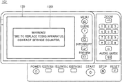
- display control unit 155 When display control unit 155 accepts a prescribed notification from life determination unit 154 , it controls control panel 102 to show a prescribed warning screen.
- FIG. 7 is a diagram representing an exemplary warning screen shown on control panel 102 .
- a prescribed warning screen 1201 pops up on touch screen 120 of control panel 102 .
- a user of image forming apparatus 100 can thus know that timing of replacement of fixing apparatus 40 has come.
- life determination unit 154 gives a prescribed notification also to communication control unit 156 .
- Communication control unit 156 is connected to an external network. Image forming apparatus 100 can thus notify an external device that fixing apparatus 40 has reached the end of its life.
- control device 101 may obtain torque Tq detected after fixation onto a recording material from driving apparatus 410 .
- control device 101 When control device 101 determines that fixing apparatus 40 has reached the end of its life, control device 101 typically stops subsequent formation of an image. Without being limited to such control, when control device 101 determines that fixing apparatus 40 has reached the end of its life, control device 101 may permit formation of an image using paper of a first type and not permit formation of an image using paper of a second type smaller in basis weight than the first type. This is because paper S larger in basis weight is less likely to slip in the nip region than paper S smaller in basis weight.
- Image forming apparatus 100 includes control device 101 that controls operations of the image forming apparatus and fixing apparatus 40 that fixes an unfixed image on paper S (a recording material) onto paper S.
- Fixing apparatus 40 includes pressurization roller 408 rotatable in a direction of downstream transportation of the recording material through the transportation path, motor 409 that rotates pressurization roller 408 , driving apparatus 410 that drives motor 409 , endless fixing belt 402 that is rotated as following rotation of pressurization roller 408 , and fixing member 490 that slidably supports fixing belt 402 from an inner surface of fixing belt 402 .
- Fixing member 490 is pressurized by pressurization roller 408 at a position where fixing belt 402 is supported.
- Driving apparatus 410 drives motor 409 so as to maintain the rotation speed of pressurization roller 408 constant based on a command from control device 101 .
- Driving apparatus 410 detects torque Tq at the time when it drives motor 409 .
- Control device 101 obtains detected torque Tq from driving apparatus 410 .
- Control device 101 determines that fixing apparatus 40 has reached the end of its life based on variation over time in torque Tg (in the present example, moving average torque Tmav calculated based on torque Tq) turning from increase to decrease.
- control device 101 each time a prescribed period (one day in the present example) elapses, control device 101 obtains torque Tq from driving apparatus 410 a plurality of times and calculates an average value of torque Tq (average torque Tav) obtained the plurality of times. Control device 101 calculates a moving average value (moving average torque Tmav) by using calculated average torque Tav and at least average torque Tav calculated the previous time. When calculated moving average torque Tmav is lower than moving average torque Tmav calculated the previous time, control device 101 determines that fixing apparatus 40 has reached the end of its life.
- Loop and reverse loop refer to a state where paper S is bent.
- Loop refers to bending of paper S that occurs in a normal condition.
- Reverse loop refers to bending of paper S reverse to loop in direction of bending.
- Image forming apparatus 100 thus determines that fixing apparatus 40 has reached the end of its life based on variation over time in moving average torque Tmav turning from increase to decrease. According to such a configuration, the end of life of fixing apparatus 40 can be determined before reverse loop occurs.
- fixing apparatus 40 can be longer in life than in the configuration in which a threshold value of torque of pressurization roller 408 used for determination of the end of life is uniquely determined.
- the end of life is determined based on moving average torque Tmav. Therefore, even though noise is introduced in torque, influence by noise can be lessened. In other words, determination of the end of life can be higher in accuracy than determination of the end of life made simply based on torque Tq.
- control device 101 obtains from driving apparatus 410 , idle torque during a period over which no paper is passing. Specifically, control device 101 obtains from driving apparatus 410 , torque Tq detected after warm-up of image forming apparatus 100 or after fixation onto paper S.
- control device 101 can highly accurately determine the end of life by obtaining torque Tq at such timing.
- FIG. 8 is a flowchart for illustrating a flow of processing performed in image forming apparatus 100 .
- control device 101 determines whether or not a torque determination permission mode has been set as a mode of determining the end of life of fixing apparatus 40 .
- the torque determination permission mode refers to a mode in which the end of life of fixing apparatus 40 is determined based on variation over time in torque Tg (in the present example, moving average torque Tmav).
- Tg in the present example, moving average torque Tmav
- a serviceperson sets the torque determination permission mode.
- control device 101 determines that the torque determination permission mode has been set (YES in step S 1 )
- control device 101 determines in step S 2 whether or not fixing apparatus 40 has reached the end of its life based on moving average torque Tmav.
- control device 101 determines in step S 3 whether or not fixing apparatus 40 has reached the end of its life based on the number of printed copies in image forming apparatus 100 and a running distance of pressurization roller 408 .
- control device 101 determines that fixing apparatus 40 has reached the end of its life. In other words, when any one of the condition of the number of printed copies and the condition of the running distance is satisfied, control device 101 determines that fixing apparatus 40 has reached the end of its life.
- FIG. 9 is a flowchart for illustrating details of processing in step S 2 in FIG. 8 .
- step S 21 fixing apparatus 40 successively detects torque Tq of pressurization roller 408 .
- step S 22 control device 101 obtains from fixing apparatus 40 , torque Tq at prescribed timing on each day. As described above, control device 101 obtains from driving apparatus 410 , torque Tq detected, for example, after warm-up of image forming apparatus 100 .
- control device 101 calculates an average value of torque Tq (average torque Tav) obtained five times at the maximum on the same day. Specifically, control device 101 performs calculation in the expression (1) described above. In step S 24 , control device 101 calculates moving average torque Tmav by using five consecutive average values.
- control device 101 updates a current value (a value of a variable) of moving average torque Tmav with the value calculated in step S 24 .
- control device 101 updates the maximum value (the value of the variable) of moving average torque Tmav with that moving average torque Tmav.
- the maximum value of moving average torque Tmav is reset (typically, set to zero) after fixing apparatus 40 is replaced. Therefore, the maximum value is the maximum value after replacement of fixing apparatus 40 .
- control device 101 compares calculated moving average torque Tmav with moving average torque Tmav_old(1) on the previous day and determines whether or not fixing apparatus 40 has reached the end of its life.
- FIG. 10 is a flowchart for illustrating details of processing in step S 27 in FIG. 9 .
- Control device 101 determines in step S 271 whether or not moving average torque Tmav is lower than moving average torque Tmav_old(1) on the previous day. When control device 101 determines that the moving average torque is lower than the moving average torque on the previous day (YES in step S 271 ), the control device determines in step S 272 that fixing apparatus 40 has reached the end of its life. As shown in FIG. 7 , control device 101 controls control panel 102 to show the warning screen in step S 273 .
- control device 101 determines that the moving average torque is not lower than the moving average torque on the previous day (NO in step S 271 ), control device 101 determines in step S 274 that fixing apparatus 40 has not yet reached the end of its life.
- FIG. 11 is a diagram showing variation over time in moving average torque.
- control device 101 determines that fixing apparatus 40 has reached the end of its life on condition that moving average torque Tmav is equal to or higher than a predetermined threshold value Th 1 . Specifically, even though variation over time in moving average torque Tmav turns from increase to decrease, control device 101 does not determine that fixing apparatus 40 has reached the end of its life when moving average torque Tmav is lower than predetermined threshold value Th 1 .
- threshold value Th 1 The reason why determination above is made based on threshold value Th 1 is because the value of moving average torque Tmav may turn to decrease due to noise or the like in spite of the fact that moving average torque Tmav is sufficiently lower than a value (numeric range) at which slip of paper S may occur in the nip region.
- FIG. 12 is a flowchart for illustrating details of processing in step S 27 in FIG. 9 in the present modification.
- the flowchart in FIG. 12 is different from the flowchart shown in FIG. 10 in including step S 275 .
- control device 101 determines in step S 271 that the moving average torque is lower than the moving average torque on the previous day (YES in step S 271 )
- the control device determines in step S 275 whether or not moving average torque Tmav is equal to or higher than threshold value Th 1 .
- Threshold value Th 1 is assumed as a positive value.
- step S 275 When control device 101 determines that moving average torque Tmav is equal to or higher than threshold value Th 1 (YES in step S 275 ), the process proceeds to step S 272 . When control device 101 determines that moving average torque Tmav is lower than threshold value Th 1 (NO in step S 275 ), the process proceeds to step S 274 .
- FIG. 13 is a diagram showing variation over time in moving average torque.
- control device 101 determines that fixing apparatus 40 has reached the end of its life on condition that an amount of lowering ⁇ Tmav is equal to or larger than a threshold value Th 2 . Specifically, even though variation over time in moving average torque Tmav turns from increase to decrease, control device 101 does not determine that fixing apparatus 40 has reached the end of its life when amount of lowering ⁇ Tmav is smaller than threshold value Th 2 .
- FIG. 14 is a flowchart for illustrating details of processing in step S 27 in FIG. 9 .
- the flowchart in FIG. 14 is different from the flowchart shown in FIG. 12 in including step S 276 .
- control device 101 determines in step S 275 that the moving average torque is equal to or higher than threshold value Th 1 (YES in step S 275 )
- the control device determines in step S 276 whether or not a difference between moving average torque Tmav and moving average torque Tmav_old(1) (that is, amount of lowering ⁇ Tmav in moving average torque Tmav) is equal to or larger than threshold value Th 2 .
- the difference is expressed as an absolute value.
- Threshold value Th 2 is assumed as a positive value.
- control device 101 determines that amount of lowering ⁇ Tmav is equal to or larger than threshold value Th 2 (YES in step S 276 ).
- the process proceeds to step S 272 .
- control device 101 determines that amount of lowering ⁇ Tmav is smaller than threshold value Th 2 (NO in step S 276 )
- the process proceeds to step S 274 .
- step S 275 Determination processing in step S 275 does not have to be performed. Specifically, when control device 101 determines in step S 271 that the moving average torque is lower than the moving average torque on the previous day (YES in step S 271 ), the process may directly proceed to step S 276 .
- FIG. 15 is a diagram showing variation over time in moving average torque.
- control device 101 determines that fixing apparatus 40 has reached the end of its life on condition that moving average torque calculated the previous time is lower than moving average torque calculated the previous time but one. In other words, control device 101 determines that fixing apparatus 40 has reached the end of its life on condition that moving average torque Tmav has lowered consecutively two times. According to such determination processing, accuracy in determination of the end of life of fixing apparatus 40 can be improved.
- FIG. 16 is a flowchart for illustrating details of processing in step S 27 in FIG. 9 in the present modification.
- the flowchart in FIG. 16 is different from the flowchart shown in FIG. 10 in including step S 277 . Specifically, when control device 101 determines in step S 271 that the moving average torque is lower than the moving average torque on the previous day (YES in step S 271 ), the control device determines in step S 277 whether or not moving average torque Tmav_old(1) on the previous day is lower than moving average torque Tmav_old(2) on the day before the previous day.
- step S 277 When control device 101 determines that moving average torque Tmav_old(1) is lower than moving average torque Tmav_old(2) (YES in step S 277 ), the process proceeds to step S 272 . When control device 101 determines that moving average torque Tmav_old(1) is not lower than moving average torque Tmav_old(2) (NO in step S 277 ), the process proceeds to step S 274 .
- control device 101 determines that fixing apparatus 40 has reached the end of its life based on variation over time in moving average torque Tmav turning from increase to decrease.
- Torque used for determination is not limited to moving average torque Tmav.
- Average torque Tav may be employed instead of moving average torque Tmav.
- torque Tq may be employed instead of moving average torque Tmav.
- Average torque calculator 152 of control device 101 calculates an average value (average torque Tav) of torque obtained five times in accordance with the expression (1) described above.
- life determination unit 154 of control device 101 determines whether or not fixing apparatus 40 has reached the end of its life based on torque Tg (average torque Tav in the present example). Specifically, life determination unit 154 determines that fixing apparatus 40 has reached the end of its life based on variation over time in average torque Tav turning from increase to decrease.
- control device 101 each time a prescribed period (for example, one day) elapses, control device 101 obtains torque from driving apparatus 410 a plurality of times and calculates an average value (average torque Tav) of torque obtained the plurality of times. When calculated average torque Tav is lower than average torque Tav calculated previously, control device 101 determines that fixing apparatus 40 has reached the end of its life.
- a prescribed period for example, one day
- control device 101 determines that fixing apparatus 40 has reached the end of its life on condition that average torque Tav is equal to or higher than a predetermined threshold value Th 1 ′.
- control device 101 determines that fixing apparatus 40 has reached the end of its life on condition that an amount of lowering ⁇ Tav is equal to or larger than a threshold value Th 2 ′.
- Amount of lowering ⁇ Tav in this case refers to a difference between average torque Tav and average torque Tav_old(1) on the previous day.
- control device 101 determines that fixing apparatus 40 has reached the end of its life on condition that average torque Tav calculated the previous time is lower than average torque Tav calculated the previous time but one.
- control device 101 Since calculation of moving average torque Tmav is not necessary in the present example, control device 101 does not have to include moving average torque calculator 153 shown in FIG. 5 .
- life determination unit 154 of control device 101 determines whether or not fixing apparatus 40 has reached the end of its life based on torque Tg (torque Tq in the present example). Specifically, life determination unit 154 determines that fixing apparatus 40 has reached the end of its life based on variation over time in torque Tq turning from increase to decrease.
- control device 101 obtains torque once from driving apparatus 410 each time a prescribed period (for example, one day) elapses.
- torque Tq is lower than previous torque Tq (torque Tq on the previous day)
- control device 101 determines that fixing apparatus 40 has reached the end of its life.
- control device 101 determines that fixing apparatus 40 has reached the end of its life on condition that torque Tq is equal to or higher than a predetermined threshold value Th 1 ′′.
- control device 101 determines that fixing apparatus 40 has reached the end of its life on condition that an amount of lowering ⁇ Tq is equal to or larger than a threshold value Th 2 ′′.
- Amount of lowering ⁇ Tq in this case refers to a difference between torque Tq and torque Tq_old(1) on the previous day.
- control device 101 determines that fixing apparatus 40 has reached the end of its life on condition that torque Tq obtained the previous time is lower than torque Tq calculated the previous time but one.
- control device 101 does not have to include average torque calculator 152 and moving average torque calculator 153 shown in FIG. 5 .
- Embodiment 1 A difference of an image forming apparatus according to the present embodiment from Embodiment 1 will be described below.
- the image forming apparatus according to the present embodiment is similar in hardware configuration to image forming apparatus 100 in Embodiment 1. Data processing performed by control device 101 is different from data processing in Embodiment 1. Therefore, description will be given below with attention being paid to data processing performed by control device 101 .
- control device 101 each time a prescribed period (for example, one day) elapses, control device 101 obtains torque Tq a plurality of times from driving apparatus 410 and calculates an average value (average torque Tav) of torque Tq obtained the plurality of times.
- torque Tq is obtained from driving apparatus 410 a plurality of times and an average value (which is referred to as “average torque Tav” also in the present embodiment) of torque Tq obtained the plurality of times is calculated.
- control device 101 obtains information on a rotation speed of pressurization roller 408 from driving apparatus 410 . Thereafter, control device 101 calculates the running distance by multiplying the rotation speed by a duration of rotation of pressurization roller 408 .
- FIG. 17 is a functional block diagram representing a functional configuration of control device 101 .
- Image forming apparatus 100 includes control device 101 , driving apparatus 410 , and control panel 102 .
- Control device 101 includes a torque obtaining unit 151 A, an average torque calculator 152 A, a moving average torque calculator 153 A, a life determination unit 154 A, display control unit 155 , and communication control unit 156 .
- Torque obtaining unit 151 A obtains torque Tq (a value of torque) from driving apparatus 410 . Specifically, torque obtaining unit 151 A obtains from driving apparatus 410 , torque Tq detected by driving apparatus 410 each time a running distance of pressurization roller 408 increases by a prescribed distance. An example in which a prescribed distance is set to “10 km” will be described below.
- Torque obtaining unit 151 A obtains torque Tq from driving apparatus 410 as being triggered by increase in running distance by 10 km. Typically, after increase in running distance by 10 km is detected, torque obtaining unit 151 A obtains from driving apparatus 410 , torque five times at the maximum within the same day on which detection was conducted. Specifically, torque obtaining unit 151 A obtains torque from driving apparatus 410 during a period over which pressurization roller 408 is in contact with fixing belt 402 as shown in FIG. 3 and no paper is passing.
- torque obtaining unit 151 A obtains from driving apparatus 410 , torque Tq detected after warm-up of image forming apparatus 100 , similarly to torque obtaining unit 151 in Embodiment 1.
- control device 101 may obtain from driving apparatus 410 , torque Tq detected after fixation onto paper S, instead of “after warm-up of image forming apparatus 100 .”
- Torque (a value of torque) obtained five times from driving apparatus 410 by torque obtaining unit 151 A is referred to as Tq(m[1]), Tq(m[2]), Tq(m[3]), Tq(m[4]), and Tq(m[5]).
- m is a variable for identifying every ten-kilometer distance. Each time the running distance increases by 10 km, the value of m is incremented by one.
- Torque obtaining unit 151 A sends torque obtained five times to average torque calculator 152 A.
- Average torque calculator 152 A calculates an average value of torque every prescribed distance. Specifically, average torque calculator 152 A calculates an average value (which is referred to as “average torque Tav′” below) of torque obtained five times as shown in an expression (4) below.
- Tav ′( m ) ( Tq ( m [1])+ Tq ( m [2])+ Tq ( m [3])+ Tq ( m [4])+ Tq ( m [5])) ⁇ 5 (4)
- Average torque calculator 152 A sends calculated average torque Tav′(m) to moving average torque calculator 153 A.
- Moving average torque calculator 153 A calculates moving average torque Tmav′ (a moving average value) by using average torque Tav′ obtained five times. Specifically, moving average torque calculator 153 A calculates moving average torque Tmav′(m) by using average torque Tav′(m) on this day and average torque obtained four times most recently (Tav′(m ⁇ 4), Tav′(m ⁇ 3), Tav′(m ⁇ 2), and Tav′(m ⁇ 1)). Specifically, moving average torque calculator 153 A performs calculation shown in an expression (5) below.
- Tmav ′( m ) ( Tav ′( m ⁇ 4)+ Tav ′( m ⁇ 3)+ Tav ′( m ⁇ 2)+ Tav ′( m ⁇ 1)+ Tav ′( m )) ⁇ 5 (5)
- Moving average torque calculator 153 A sends calculated moving average torque Tmav′(m) to life determination unit 154 A. Though moving average torque Tmav′ is calculated by using average torque Tav′ obtained five times (five pieces), the number of pieces of average torque Tav′ is not limited to five.
- Life determination unit 154 A determines whether or not fixing apparatus 40 has reached the end of its life. Specifically, life determination unit 154 A determines whether or not fixing apparatus 40 has reached the end of its life based on moving average torque Tmav′. More specifically, life determination unit 154 A determines that fixing apparatus 40 has reached the end of its life based on variation over time in moving average torque Tmav′ turning from increase to decrease.
- FIG. 18 is a diagram showing variation over time in moving average torque Tmav′.
- the abscissa in the graph (figure) represents a running distance (km) and the ordinate in the graph represents moving average torque Tmav′.
- Moving average torque Tmav′ monotonously increases until a distance L(m ⁇ 1). Moving average torque Tmav′(m) at a distance L(m) is lower than moving average torque Tmav′(m ⁇ 1) at a previous distance L(m ⁇ 1). In other words, relation of “Tmav′(m ⁇ 1)>Tmav′(m)” is satisfied.
- life determination unit 154 A determines that fixing apparatus 40 has reached the end of its life at the time point when distance L(m) is reached (specifically, the time point of calculation of Tmav′(m)).
- life determination unit 154 A determines that the fixing apparatus has reached the end of its life, it gives a prescribed notification to display control unit 155 .
- display control unit 155 When display control unit 155 accepts a prescribed notification from life determination unit 154 A, it controls control panel 102 to show a prescribed warning screen (see FIG. 7 ).
- Driving apparatus 410 drives motor 409 so as to maintain the rotation speed of pressurization roller 408 constant based on a command from control device 101 .
- Driving apparatus 410 detects torque at the time when it drives motor 409 .
- Control device 101 obtains detected torque Tq from driving apparatus 410 .
- Control device 101 determines that fixing apparatus 40 has reached the end of its life based on variation over time in torque Tg (in the present example, moving average torque Tmav′) turning from increase to decrease.
- control device 101 each time the running distance of pressurization roller 408 increases by a prescribed distance (10 km in the present example), control device 101 obtains torque Tq from driving apparatus 410 a plurality of times and calculates an average value (average torque Tav′) of torque Tq obtained the plurality of times. Control device 101 calculates a moving average value (moving average torque Tmav′) by using calculated average torque Tav′ and at least average torque Tav′ calculated previously. When calculated moving average torque Tmav′ is lower than moving average torque Tmav′ calculated previously, control device 101 determines that fixing apparatus 40 has reached the end of its life.
- Processing shown in FIG. 8 is performed also in the present embodiment as in Embodiment 1.
- FIG. 19 is a flowchart for illustrating details of processing in step S 2 in FIG. 8 .
- step S 21 fixing apparatus 40 successively detects torque Tq of pressurization roller 408 .
- step S 22 A control device 101 obtains torque Tq at prescribed timing from fixing apparatus 40 each time the running distance of pressurization roller 408 increases by a prescribed distance. As described above, control device 101 obtains from driving apparatus 410 , torque Tq detected, for example, after warm-up of image forming apparatus 100 .
- control device 101 calculates an average value (average torque Tav′) of torque Tq obtained five times at the maximum on the same day. Specifically, control device 101 performs calculation in the expression (4) described above. In step S 24 A, control device 101 calculates moving average torque Tmav′ by using five consecutive average values.
- control device 101 updates a current value (a value of a variable) of moving average torque Tmav′ with the value calculated in step S 24 A.
- control device 101 updates the maximum value (the value of the variable) of moving average torque Tmav′ with that moving average torque Tmav′.
- the maximum value of moving average torque Tmav′ is reset (typically, set to zero) after fixing apparatus 40 is replaced. Therefore, the maximum value is a maximum value after replacement of fixing apparatus 40 .
- control device 101 compares calculated moving average torque Tmav′ with previous moving average torque Tmav′_old(1) and determines whether or not fixing apparatus 40 has reached the end of its life.
- FIG. 20 is a flowchart for illustrating details of processing in step S 27 A in FIG. 19 .
- Control device 101 determines in step S 271 A whether or not moving average torque Tmav′ is lower than previous moving average torque Tmav′_old(1). When control device 101 determines that the moving average torque is lower than the previous moving average torque (YES in step S 271 A), the control device determines in step S 272 that fixing apparatus 40 has reached the end of its life. As shown in FIG. 7 , control device 101 controls control panel 102 to show the warning screen in step S 273 .
- control device 101 determines that the moving average torque is not lower than the previous moving average torque (NO in step S 271 A)
- control device 101 determines in step S 274 that fixing apparatus 40 has not yet reached the end of its life.
- Control device 101 may determine that fixing apparatus 40 has reached the end of its life when the calculated average value (average torque Tay′) is smaller than the average value calculated previously.
- control device 101 may determine that fixing apparatus 40 has reached the end of its life when obtained torque Tq is lower than torque Tq obtained previously.
- Embodiment 1 The present embodiment is different from Embodiment 1 and Embodiment 2 in determination of the end of life after it is determined that the torque determination permission mode has been set, which will be described below.
- FIG. 21 is a flowchart for illustrating a flow of processing performed in image forming apparatus 100 .
- Control device 101 determines in step S 1 whether or not the torque determination permission mode has been set as a mode of determining the end of life of fixing apparatus 40 .
- control device 101 determines that the torque determination permission mode has been set (YES in step S 1 )
- the control device determines in step S 2 A whether or not fixing apparatus 40 has reached the end of its life based on the number of printed copies in image forming apparatus 100 and the running distance of pressurization roller 408 as well as on moving average torque Tmav′.
- control device 101 determines that the torque determination permission mode has not been set (NO in step S 1 )
- the control device determines in step S 3 whether or not fixing apparatus 40 has reached the end of its life based on the number of printed copies in image forming apparatus 100 and the running distance of pressurization roller 408 .
- step S 2 A in the present embodiment, when the torque determination permission mode has been set, the end of life of fixing apparatus 40 is determined in consideration not only of moving average torque Tmav′ but also the number of printed copies and the running distance of pressurization roller 408 . Therefore, control device 101 can more accurately determine the end of life in the torque determination permission mode.
- FIG. 22 is a diagram representing a network configuration of an information processing system 1 .
- Information processing system 1 includes image forming apparatus 100 and a server apparatus 900 .
- Image forming apparatus 100 and server apparatus 900 are communicatively connected to each other over a network 901 .
- Image forming apparatus 100 communicates with server apparatus 900 by means of communication control unit 156 (see FIG. 5 ).
- server apparatus 900 obtains torque Tq detected in driving apparatus 410 through network 901 .
- Server apparatus 900 calculates average torque Tav (or Tav′) and moving average torque Tmav (or Tmav′). Furthermore, server apparatus 900 determines the end of life of fixing apparatus 40 based on moving average torque Tmav (or Tmav′).
- Information processing system 1 may be configured such that image forming apparatus 100 calculates moving average torque Tmav (or Tmav′) and server apparatus 900 determines the end of life.
- driving apparatus 410 detects torque at the time when motor 409 is driven in Embodiments 1 to 4 above, limitation thereto is not intended.
- control device 101 may detect torque at the time when motor 409 is driven.
- a not-shown device within image forming apparatus 100 may detect torque at the time when motor 409 is driven.
- Image forming apparatus 100 should only perform at least a function to detect torque at the time when motor 409 is driven.
- torque detector 413 shown in FIG. 4 should only be provided somewhere in image forming apparatus 100 .
- torque detector 413 may be located within or outside fixing apparatus 40 .
- Such a function to detect torque can be implemented, for example, by at least one processor.
- control device 101 should only obtain torque at the time when motor 409 is driven each time a predetermined condition is satisfied, and determine that fixing apparatus 40 has reached the end of its life based on variation over time in obtained torque turning from increase to decrease.
- image forming apparatus 100 can also be defined as being configured below.
- Image forming apparatus 100 includes at least fixing apparatus 40 that fixes unfixed image G on paper S (a recording material) onto paper S and forms an image on paper S.
- Image forming apparatus 100 includes pressurization roller (pressurization member) 408 that is rotated by motor 409 in the direction of downstream transportation in fixing apparatus 40 , of paper S through a transportation path, fixing belt 402 that forms, as being opposed to pressurization roller 408 , a nip region where unfixed image G is fixed, and is rotated as following rotation of pressurization roller 408 , fixing member (support member) 490 that is arranged on the inner side of fixing belt 402 and slidably supports fixing belt 402 at a position opposed to pressurization roller 408 against a pressure applied by pressurization roller 408 , and control device (control unit) 101 that obtains torque at the time when motor 409 is driven each time a predetermined condition is satisfied and determines that fixing apparatus 40 has reached the end of its life based on variation over time in obtained torque turning from increase to decrease.
- pressurization roller pressurization member
- fixing belt 402 that forms, as being opposed to pressurization roller 408 , a nip region where unfixed
- server apparatus (information processing apparatus) 900 should only obtain from image forming apparatus 100 , torque at the time when motor 409 is driven each time a predetermined condition is satisfied and determine that fixing apparatus 40 has reached the end of its life based on variation over time in obtained torque turning from increase to decrease.
- image forming apparatus 100 can be defined as being configured below.
- Information processing system 1 includes image forming apparatus 100 that includes at least fixing apparatus 40 that fixes unfixed image G on paper S (a recording material) onto paper S and forms an image on paper S and server apparatus (information processing apparatus) 900 .
- Image forming apparatus 100 includes pressurization roller (pressurization member) 408 that is rotated by motor 409 in the direction of downstream transportation of paper S, in fixing apparatus 40 through a transportation path, fixing belt 402 that forms, as being opposed to pressurization roller 408 , a nip region where unfixed image G is fixed, and is rotated as following rotation of pressurization roller 408 , and fixing member (support member) 490 that is arranged on the inner side of fixing belt 402 and slidably supports fixing belt 402 at a position opposed to pressurization roller 408 against a pressure applied by pressurization roller 408 .
- pressurization roller pressurization member
- fixing belt 402 that forms, as being opposed to pressurization roller 408 , a nip region where unfixed image G is fixed, and is rotated as following rotation of pressurization roller 408
- fixing member (support member) 490 that is arranged on the inner side of fixing belt 402 and slidably supports fixing belt 402 at a position opposed to press
- Server apparatus 900 obtains from image forming apparatus 100 , torque at the time when motor 409 is driven each time a predetermined condition is satisfied. Server apparatus 900 determines that fixing apparatus 40 has reached the end of its life based on variation over time in obtained torque turning from increase to decrease.
- An image forming apparatus includes at least a fixing apparatus that fixes onto a recording material, an unfixed image on the recording material, and forms an image on the recording material.
- the image forming apparatus includes a pressurization member that is rotated by a motor in a direction of downstream transportation in the fixing apparatus, of the recording material through a transportation path, a fixing belt that forms, as being opposed to the pressurization member, a nip region where the unfixed image is fixed, and is rotated as following rotation of the pressurization member, a support member that is arranged on an inner side of the fixing belt and slidably supports the fixing belt at a position opposed to the pressurization member against a pressure applied by the pressurization member, and a control unit that obtains torque at the time when the motor is driven each time a predetermined condition is satisfied, and determines that the fixing apparatus has reached the end of its life based on variation over time in obtained torque turning from increase to decrease.
- the predetermined condition is increase in running distance of the pressurization member by a prescribed distance.
- the control unit obtains torque each time the running distance of the pressurization member increases by the prescribed distance.
- the control unit determines that the fixing apparatus has reached the end of its life when the obtained torque is lower than torque obtained previously.
- the predetermined condition is increase in running distance of the pressurization member by a prescribed distance.
- the control unit obtains torque a plurality of times each time the running distance of the pressurization member increases by the prescribed distance and calculates an average value of torque obtained the plurality of times.
- the control unit determines that the fixing apparatus has reached the end of its life when the calculated average value is smaller than the average value calculated previously.
- the predetermined condition is increase in running distance of the pressurization member by a prescribed distance.
- the control unit obtains torque a plurality of times each time the running distance of the pressurization member increases by the prescribed distance and calculates an average value of torque obtained the plurality of times.
- the control unit calculates a moving average value by using the calculated average value and at least the average value calculated previously.
- the control unit determines that the fixing apparatus has reached the end of its life when the calculated moving average value is smaller than the moving average value calculated previously.
- the predetermined condition is lapse of a prescribed period.
- the control unit obtains torque each time the prescribed period elapses.
- the control unit determines that the fixing apparatus has reached the end of its life when the obtained torque is lower than torque obtained previously.
- the predetermined condition is lapse of a prescribed period.
- the control unit obtains torque a plurality of times each time the prescribed period elapses and calculates an average value of torque obtained the plurality of times.
- the control unit determines that the fixing apparatus has reached the end of its life when the calculated average value is smaller than the average value calculated previously.
- the predetermined condition is lapse of a prescribed period.
- the control unit obtains torque a plurality of times each time the prescribed period elapses and calculates an average value of torque obtained the plurality of times.
- the control unit calculates a moving average value by using the calculated average value and at least the average value calculated previously.
- the control unit determines that the fixing apparatus has reached the end of its life when the calculated moving average value is smaller than the moving average value calculated previously.
- control unit obtains information on a rotation speed of the pressurization member.
- the control unit calculates the running distance by multiplying the rotation speed by a duration of rotation of the pressurization member.
- the control unit obtains as the torque, idle torque during a period over which no paper is passing.
- the control unit obtains as the torque, idle torque during a period over which no paper is passing.
- control unit obtains as the idle torque during the period over which no paper is passing, torque detected after warm-up of the image forming apparatus or after fixation onto the recording material.
- control unit determines that the fixing apparatus has reached the end of its life on condition that the obtained torque is equal to or higher than a predetermined threshold value.
- control unit determines that the fixing apparatus has reached the end of its life on condition that the calculated average value is equal to or larger than a predetermined threshold value.
- control unit determines that the fixing apparatus has reached the end of its life on condition that the calculated moving average value is equal to or larger than a predetermined threshold value.
- the control unit determines that the fixing apparatus has reached the end of its life on condition that the torque obtained the previous time is lower than the torque obtained the previous time but one.
- the control unit determines that the fixing apparatus has reached the end of its life on condition that the average value calculated the previous time is smaller than the average value calculated the previous time but one.
- the control unit determines that the fixing apparatus has reached the end of its life on condition that the moving average value calculated the previous time is smaller than the moving average value calculated the previous time but one.
- control unit determines that the fixing apparatus has reached the end of its life
- control unit permits formation of an image using paper of a first type and does not permit formation of an image using paper of a second type smaller in basis weight than the paper of the first type.
- the image forming apparatus further includes a control panel.
- the control unit determines that the fixing apparatus has reached the end of its life, the control unit controls the control panel to show a prescribed image.
- An information processing system includes an image forming apparatus that includes at least a fixing apparatus that fixes onto a recording material, an unfixed image on the recording material and forms an image on the recording material and an information processing apparatus.
- the image forming apparatus includes a pressurization member that is rotated by a motor in a direction of downstream transportation in the fixing apparatus, of the recording material through a transportation path, a fixing belt that forms, as being opposed to the pressurization member, a nip region where the unfixed image is fixed, and is rotated as following rotation of the pressurization member, and a support member that is arranged on an inner side of the fixing belt and slidably supports the fixing belt at a position opposed to the pressurization member against a pressure applied by the pressurization member.
- the image forming apparatus detects torque at the time when the motor is driven.
- the information processing apparatus obtains from the image forming apparatus, torque at the time when the motor is driven each time a predetermined condition is satisfied.
- the information processing apparatus determines that the fixing apparatus has reached the end of its life based on variation over time in obtained torque turning from increase to decrease.
- An information processing method is performed in an image forming apparatus that includes at least a fixing apparatus that fixes onto a recording material, an unfixed image on the recording material and forms an image on the recording material.
- the image forming apparatus includes a control unit, a pressurization member that is rotated by a motor in a direction of downstream transportation in the fixing apparatus, of the recording material through a transportation path, a fixing belt that forms, as being opposed to the pressurization member, a nip region where the unfixed image is fixed, and is rotated as following rotation of the pressurization member, and a support member that is arranged on an inner side of the fixing belt and slidably supports the fixing belt at a position opposed to the pressurization member against a pressure applied by the pressurization member.
- the information processing method includes obtaining, by the control unit, torque at the time when the motor is driven each time a predetermined condition is satisfied and determining, by the control unit, that the fixing apparatus has reached the end of its life based on variation over time in obtained torque turning from increase to decrease.
- torque (torque of the pressurization roller) at which slip of paper is expected to occur may be determined in advance and set as a reference value (threshold value) in determination of life.
- Torque at the time of slip of paper is varied also by a state of pressurization (load) by the pressurization roller. Therefore, it is difficult to uniquely determine the reference value. Therefore, according to the conventional technique, the fixing apparatus has consequently been determined as reaching the end of its life in a stage quite earlier than the actual end of its life.
- the present disclosure also provides an image forming apparatus, an information processing system, and an information processing method capable of achieving higher accuracy in determination of the end of life of a fixing apparatus as in Disclosure I.
- FIG. 23 is a block diagram for illustrating a hardware configuration of image forming apparatus 100 .
- Image forming apparatus 100 includes at least control device (control unit) 101 , control panel 102 , fixing apparatus 40 , and a sensor device (detector) 60 .
- Sensor device 60 includes a lever 61 and a photosensor 62 .
- Sensor device 60 is provided between secondary transfer roller 33 as a transfer apparatus (transfer unit) that transfers an image to paper S and fixing apparatus 40 (specifically, pressurization roller 408 of fixing apparatus 40 ) and detects a state of paper S. Specifically, sensor device 60 detects whether or not paper S is deflected in a predetermined direction (a first direction).
- a state in which paper S is deflected in a predetermined direction is also referred to as a “loop state” or a “forward loop state” below. Though details will be described later, the loop state refers to bending of paper S that occurs in a normal condition.
- sensor device 60 When paper S is in the loop state, sensor device 60 transmits a predetermined signal (an on signal) to control device 101 . When paper S is deflected in a direction (a second direction) reverse to the predetermined direction, sensor device 60 does not transmit the predetermined signal (on signal) to control device 101 .
- the predetermined signal is also referred to as a “detection signal.”
- reverse loop state a state in which paper S is deflected in the direction reverse to the predetermined direction.
- the reverse loop state refers to bending of paper S reverse in direction to the loop state and deflection of paper S in an abnormal condition.
- sensor device 60 Details of sensor device 60 , the loop state, and the reverse loop state will be described later.
- Control device 101 determines at least whether or not paper S is in the “loop state” based on presence of a signal output from sensor device 60 . More specifically, control device 101 determines also whether or not paper S is in the “reverse loop state” through processing which will be described later.
- FIG. 24 is an enlarged view of a main portion of image forming apparatus 100 .
- Image forming apparatus 100 includes fixing apparatus 40 , secondary transfer roller 33 , intermediate transfer belt 30 , sensor device 60 , a separation tab 71 , and paper passage guides 72 , 73 , 74 , and 75 .
- Sensor device 60 includes lever 61 described above, a rotation shaft 611 , and photosensor 62 (see FIG. 23 ).
- Separation tab 71 serves to remove paper S from intermediate transfer belt 30 when paper S does not come off from intermediate transfer belt 30 and to transport paper S toward fixing apparatus 40 .
- Paper passage guides 72 to 75 serve to guide paper S to fixing apparatus 40 .
- Paper passage guide 72 is provided above separation tab 71 (on a side of fixing apparatus 40 ).
- Paper passage guide 73 is provided above paper passage guide 72 and below fixing belt 402 of fixing apparatus 40 .
- Paper passage guide 74 is provided at a position opposed to paper passage guide 72 and above secondary transfer roller 33 .
- Paper passage guide 75 is provided under pressurization roller 408 and above paper passage guide 74 .
- Paper passage guide 75 serves to transport paper S to the nip region in fixing apparatus 40 .
- Regions R 1 , R 2 , and R 3 are regions where a print surface of paper S may be in contact therewith when paper S cannot appropriately be transported (for example, paper S is in the reverse loop state). When the print surface of paper S comes in contact with regions R 1 , R 2 , and R 3 , rubbing of an image occurs.
- Lever 61 of sensor device 60 is pivoted around rotation shaft 611 . Specifically, as a result of contact with paper S, lever 61 is pivoted clockwise by a prescribed angle from an illustrated position (which is also referred to as a “default position” below). The position of lever 61 after pivot by a prescribed angle is also referred to as an “end point position” below for the sake of convenience of description. When there is no contact with paper S, lever 61 returns to the default position. Lever 61 thus takes a different position depending on presence of contact with paper S.
- Not-shown photosensor 62 does not output a detection signal to control device 101 when lever 61 is located at the default position.
- photosensor 62 When lever 61 is located at the end point position, photosensor 62 outputs the detection signal to control device 101 .
- an on state (a state in which a signal is output) is set, and when lever 61 is located at the default position (the position shown in FIG. 24 ), an off state (a state in which a signal is not output) is set.
- Loop control is started immediately before paper S enters fixing apparatus 40 . Until loop control is started, pressurization roller 408 continues to rotate at high-speed side speed VH described above. Loop control is also referred to as “forward loop control” below for distinction from reverse loop control which will be described later.
- FIG. 25 is a diagram showing a state in which paper S is not looping.
- Paper S is substantially straight between secondary transfer roller 33 and fixing apparatus 40 .
- the straight state refers to a state without deflection between a region of contact between secondary transfer roller 33 and intermediate transfer belt 30 and the nip region in fixing apparatus 40 .
- control device 101 switches the rotation speed of pressurization roller 408 from high-speed side speed VH to low-speed side speed VL. The tensioned state of paper S is thus relaxed.
- FIG. 26 is a diagram showing a state in which paper S is looping.
- a central portion of paper S is deflected between secondary transfer roller 33 and fixing apparatus 40 in a positive direction along an X axis in the figure.
- paper S is curved.
- paper S is slack.
- the central portion of paper S is displaced in a direction toward sensor device 60 as compared with the state in which paper S is straight.
- the state in which paper S is deflected in the direction as in FIG. 26 is referred to as the “forward loop state” as described above.
- control device 101 When control device 101 accepts input of a signal from photosensor 62 while the rotation speed of pressurization roller 408 is set to low-speed side speed VL, it switches the rotation speed of pressurization roller 408 from low-speed side speed VL to high-speed side speed VH. Slack of paper S can thus be eliminated.
- control device 101 adjusts the rotation speed of pressurization roller 408 in accordance with presence of the detection signal from sensor device 60 . Under such speed control, paper S can enter fixing apparatus 40 in an appropriate state.
- the reverse loop state is less likely in paper of basis weight equal to or larger than prescribed basis weight (for example, paper equal to or larger than plain paper in basis weight).
- prescribed basis weight for example, paper equal to or larger than plain paper in basis weight.
- paper having rigidity equal to or higher than a prescribed level is less likely to be in the reverse loop state.
- Paper small in basis weight such as thin paper is more likely to be in the reverse loop state than paper large in basis weight.
- FIG. 27 is a diagram for illustrating the reverse loop state.
- paper S moves in a direction shown with an arrow W, the paper enters the reverse loop state. Specifically, the central portion of paper S is deflected in a negative direction along the X axis in the figure between secondary transfer roller 33 and fixing apparatus 40 . In other words, paper S is opposite in the direction of curving to the curved state in FIG. 26 . Specifically, the central portion of paper S is displaced toward paper passage guides 72 and 73 as compared with the state in which paper S is straight.
- Control device 101 determines that paper S tends to be tensioned in spite of slack in paper S.
- the rotation speed of pressurization roller 408 is maintained at low-speed side speed VL, deflection will be larger. In other words, slack of paper S will increase.
- control device 101 carries out reverse loop control which will be described below.
- control device 101 When there is no input of detection signal for a prescribed time period (which is also referred to as a “set time period TC 1 ” below) set for starting control, control device 101 varies the rotation speed of pressurization roller 408 until it receives input of the detection signal. Typically, control device 101 switches the rotation speed of pressurization roller 408 between speed VH and speed VL. For example, control device 101 switches the rotation speed with a predetermined period.
- FIG. 28 is a diagram illustrating how to vary a rotation speed of pressurization roller 408 .
- control device 101 When set time period TC 1 has elapsed since there was no input of a detection signal, control device 101 periodically switches the rotation speed of pressurization roller 408 . In other words, when set time period TC 1 has elapsed since the rotation speed was set to speed VL, control device 101 periodically switches the rotation speed of pressurization roller 408 . Specifically, when set time period TC 1 has elapsed, control device 101 sets the rotation speed to speed VH for a time period TD. After control device 101 sets the rotation speed to speed VH for time period TD, it sets the rotation speed to speed VL for a time period TE. Similarly also thereafter, the control device switches the rotation speed between speed VH and speed VL. Time period TD and time period TE are typically equal to each other.
- lever 61 When paper S is set to the forward loop state, lever 61 reaches the end point position and hence control device 101 receives the detection signal. Thereafter, forward loop control described above is carried out.
- control device 101 determines whether or not fixing apparatus 40 has reached the end of its life based on a result of reverse loop control.
- control device 101 determines that fixing apparatus 40 has reached the end of its life.
- the time period for which the rotation speed of pressurization roller 408 is varied is the sum of a time period calculated by multiplying time period TD by an integer and a time period calculated by multiplying time period TE by an integer.
- speed variation duration Tz is also in proportion to the number of times of switching of the rotation speed of pressurization roller 408 . Therefore, when the number of times of switching of the rotation speed of pressurization roller 408 is equal to or larger than the number determined by a period f of variation and set time period TC 2 , control device 101 may determine that fixing apparatus 40 has reached the end of its life.
- control device 101 determines that fixing apparatus 40 has reached the end of its life.
- a value obtained by dividing set time period TC 2 by period f (TC 2 / f ) is a decimal value
- control device 101 may determine that fixing apparatus 40 has reached the end of its life when the number of times of switching of the rotation speed is larger than a value (an integral value) calculated by rounding up the first decimal place of that value.
- control device 101 may determine that fixing apparatus 40 has reached the end of its life.
- Speed variation duration Tz may exceed time period TC 2 accidentally only once. In this case, it may not be preferred to determine that fixing apparatus 40 has reached the end of its life.
- control device 101 may make determination as to life of fixing apparatus 40 .
- fixing apparatus 101 does not constantly make determination as to life of fixing apparatus 40 but may make determination as to life each time a predetermined condition is satisfied.
- control device 101 determines the end of life of fixing apparatus 40 each time a predetermined condition is satisfied as such.
- control device 101 determines that fixing apparatus 40 has reached the end of its life when a time period (speed variation duration Tz) for which the rotation speed of pressurization roller 408 is varied is equal to or longer than the prescribed time period (set time period TC 2 ) set for determination of the end of life.
- speed variation duration Tz is set to a time period required for carrying out reverse loop control once (the sum of a time period calculated by multiplying time period TD by an integer and a time period calculated by multiplying time period TE by an integer (see FIG. 28 )). Limitation thereto, however, is not intended.
- control device 101 may regard speed variation duration Tz as a cumulative value (which is also referred to as a “cumulative time period” below) of a time period required for each time of reverse loop control and determine that fixing apparatus 40 has reached the end of its life when the cumulative time period is equal to or longer than a set time period Tc.
- control device 101 may determine that fixing apparatus 40 has reached the end of its life based on a time period required for reverse loop control for each of a plurality of sheets of paper S (that is, the cumulative time period), rather than a time period required for reverse loop control for one sheet of paper S (which is also referred to as an “elementary time period” below).
- control device 101 Accumulation of time periods required for reverse loop control and calculation of the cumulative time period based on the accumulated time periods are carried out by control device 101 .
- FIG. 29 is a functional block diagram representing a functional configuration of control device 101 .
- Image forming apparatus 100 includes control device 101 , driving apparatus 410 , control panel 102 , and sensor device 60 .
- Control device 101 includes a rotation speed control unit 1150 , a life determination unit 1154 , a display control unit 1155 , and a communication control unit 1156 .
- Rotation speed control unit 1150 controls a rotation speed of pressurization roller 408 . Specifically, rotation speed control unit 1150 controls the rotation speed of pressurization roller 408 by sending a speed command to motor control device 411 (see FIG. 4 in Disclosure I) of driving apparatus 410 .
- rotation speed control unit 1150 receives a detection signal from sensor device 60 . Specifically, rotation speed control unit 1150 receives a detection signal output from photosensor 62 , based on movement of lever 61 from the default position to the end point position as a result of contact with paper S. Rotation speed control unit 1150 controls the rotation speed of pressurization roller 408 based on whether or not it has received the detection signal.
- rotation speed control unit 1150 controls the rotation speed of pressurization roller 408 to speed VH or speed VL based on whether or not it receives the detection signal.
- rotation speed control unit 1150 varies the rotation speed of pressurization roller 408 until it receives input of the detection signal.
- rotation speed control unit 1150 switches the rotation speed of pressurization roller 408 between speed VH and speed VL.
- rotation speed control unit 1150 When paper is in the reverse loop state, rotation speed control unit 1150 gives life determination unit 1154 information on speed variation duration Tz for which the rotation speed of pressurization roller 408 is varied. Rotation speed control unit 1150 may give life determination unit 1154 information on count of variation, instead of information on speed variation duration Tz.
- Life determination unit 1154 determines whether or not fixing apparatus 40 has reached the end of its life. Specifically, life determination unit 1154 determines whether or not fixing apparatus 40 has reached the end of its life based on information on speed variation duration Tz (or alternatively count information) obtained from rotation speed control unit 1150 . Specifically, when speed variation duration Tz is equal to or longer than set time period TC 2 described above, life determination unit 1154 determines that fixing apparatus 40 has reached the end of its life. When life determination unit 1154 determines that the fixing apparatus has reached the end of its life, life determination unit 1154 gives a prescribed notification to display control unit 1155 .
- display control unit 1155 When display control unit 1155 accepts the prescribed notification from life determination unit 1154 , it controls control panel 102 to show prescribed warning screen 1201 (see FIG. 7 in Disclosure I).
- life determination unit 1154 gives a prescribed notification also to communication control unit 1156 .
- Communication control unit 1156 is connected to an external network. Image forming apparatus 100 can thus notify an external device that fixing apparatus 40 has reached the end of its life.
- control device 101 When control device 101 determines that fixing apparatus 40 has reached the end of its life, control device 101 typically stops subsequent formation of an image. Without being limited to such control, when control device 101 determines that fixing apparatus 40 has reached the end of its life, control device 101 may permit formation of an image using paper of a first type and may not permit formation of an image using paper of a second type smaller in basis weight than the paper of the first type. Paper S large in basis weight is less likely to be in the reverse loop state than paper S small in basis weight.
- the reverse loop state normally does not occur in paper equal to or larger than plain paper in basis weight.
- paper smaller in basis weight such as thin paper is more likely to be in the reverse loop state than paper larger in basis weight.
- control device 101 preferably obtains information on speed variation duration Tz during reverse loop control for each type of paper (thin paper, plain paper, or cardboard).
- control device 101 may determine that fixing apparatus 40 has reached the end of its life when speed variation duration Tz is equal to or longer than set time period TC 2 for paper of a type equal to or larger than plain paper in basis weight.
- control device 101 may determine that fixing apparatus 40 has reached the end of its life when speed variation duration Tz is equal to or longer than set time period TC 2 for thin paper and further for paper of a type equal to or larger than plain paper in basis weight.
- image forming apparatus 100 includes control device 101 that controls operations of the image forming apparatus, a transfer apparatus (secondary transfer roller 33 ) that transfers an image onto paper S (a recording material), fixing apparatus 40 that fixes an unfixed image on paper S onto paper S, and sensor device 60 that is provided between the transfer apparatus and fixing apparatus 40 and detects a state of paper S.
- control device 101 controls operations of the image forming apparatus
- a transfer apparatus secondary transfer roller 33
- fixing apparatus 40 that fixes an unfixed image on paper S onto paper S
- sensor device 60 that is provided between the transfer apparatus and fixing apparatus 40 and detects a state of paper S.
- the transfer apparatus transports paper S to fixing apparatus 40 at a predetermined speed.
- Fixing apparatus 40 includes pressurization roller 408 and pressurization roller 408 transports paper S transported from the transfer apparatus, downstream through the transportation path.
- sensor device 60 When paper S is deflected in the first direction (the positive direction along the X axis in FIG. 24 ), sensor device 60 outputs a detection signal (a predetermined signal) to control device 101 , and when paper S is deflected in the second direction (the negative direction along the X axis in FIG. 24 ) reverse to the first direction, it does not output the detection signal to control device 101 .
- control device 101 While control device 101 receives input of the detection signal, control device 101 controls the rotation speed of pressurization roller 408 to speed VH (the first speed), and while it does not receive input of the detection signal, it controls the rotation speed of pressurization roller 408 to speed VL (the second speed) lower than speed VH. While control device 101 does not receive input of the detection signal for set time period TC 1 (the first time period), control device 101 varies the rotation speed of pressurization roller 408 until it receives input of the detection signal. When a time period for which control device 101 varies the rotation speed of pressurization roller 408 is equal to or longer than set time period TC 2 (the second time period), control device 101 determines that fixing apparatus 40 has reached the end of its life.
- the end of life is determined with attention being paid to a reverse loop phenomenon based on deterioration of fixing apparatus 40 . Therefore, the end of life of fixing apparatus 40 can be determined more accurately than in a configuration where the threshold value for torque of pressurization roller 408 used for determination of the end of life is uniquely determined. Therefore, according to the configuration, timing of replacement of fixing apparatus 40 can be postponed and hence life of fixing apparatus 40 can be longer than in the conventional example.
- Control device 101 varies the rotation speed of pressurization roller 408 by switching the rotation speed of pressurization roller 408 between speed VH and speed VL.
- control device 101 determines that fixing apparatus 40 has reached the end of its life.
- control device 101 determines that fixing apparatus 40 has reached the end of its life. According to the configuration, the end of life can more accurately be determined.
- control device 101 makes determination as to the end of life of fixing apparatus 40 .
- Sensor device 60 includes lever 61 and photosensor 62 .
- lever 61 When paper S is deflected in the second direction (the negative direction along the X axis in FIG. 24 ), lever 61 is located at the default position (the first position), and when paper S is deflected in the first direction (the positive direction along the X axis), lever 61 is moved from the default position to the end point position (the second position) by paper S.
- photosensor 62 outputs the detection signal to control device 101 .
- a time period for which the rotation speed of pressurization roller 408 is varied is a cumulative value of a time period (elementary time period) for which the rotation speed of pressurization roller 408 is varied for each of a plurality of sheets of paper S.
- Image forming apparatus 100 can also be defined as being configured below.
- Image forming apparatus 100 includes at least fixing apparatus 40 that fixes an unfixed image on paper S onto paper S and forms an image on paper S.
- Image forming apparatus 100 includes a transfer apparatus (a transfer unit or secondary transfer roller 33 ) that transfers an image onto paper S and transports paper S downstream through a transportation path, pressurization roller (pressurization member) 408 that can be rotated in a direction of downstream transportation in fixing apparatus 40 through the transportation path, of paper S from the transfer apparatus, fixing belt 402 that forms, as being opposed to pressurization roller 408 , a nip region where unfixed image G is fixed, and is rotated as following rotation of pressurization roller 408 , sensor device (detector) 60 that is provided between the transfer apparatus and pressurization roller 408 and detects a state of paper S, and control device (control unit) 101 .
- a transfer apparatus a transfer unit or secondary transfer roller 33
- pressurization roller (pressurization member) 408 that can be rotated in a direction of downstream transportation in fixing apparatus 40 through the
- sensor device 60 When paper S is deflected in the first direction (the positive direction along the X axis in FIG. 24 ), sensor device 60 outputs a detection signal (a predetermined signal) to control device 101 , and when paper S is deflected in the second direction (the negative direction along the X axis in FIG. 24 ) reverse to the first direction, it does not output the detection signal to control device 101 .
- a detection signal a predetermined signal
- control device 101 While control device 101 receives input of the detection signal, control device 101 controls the rotation speed of pressurization roller 408 to speed VH (the first speed), and while control device 101 does not receive input of the detection signal, control device 101 controls the rotation speed of pressurization roller 408 to speed VL (the second speed) lower than speed VH. While control device 101 does not receive input of the detection signal for set time period TC 1 (the first time period), control device 101 varies the rotation speed of pressurization roller 408 until it receives input of the detection signal. When a time period for which the rotation speed of pressurization roller 408 is varied is equal to or longer than set time period TC 2 (the second time period), control device 101 determines that fixing apparatus 40 has reached the end of its life.
- FIG. 30 is a flowchart representing a flow of processing performed by control device 101 .
- Control device 101 determines in step S 500 whether or not paper S has reached a prescribed position immediately before entry into fixing apparatus 40 .
- control device 101 determines that paper has reached the prescribed position (YES in step S 500 )
- control device 101 starts in step S 510 forward loop control described above.
- control device 101 determines that paper has not reached the prescribed position (NO in step S 500 )
- control device 101 allows the process to proceed to step S 500 .
- step S 520 control device 101 determines whether or not paper S has passed through fixing apparatus 40 .
- control device 101 determines that paper S has passed through fixing apparatus 40 (YES in step S 520 )
- control device 101 quits a series of processing.
- control device 101 determines in step S 530 whether or not reception of a detection signal from sensor device 60 is continuously absent for set time period TC 1 .
- control device 101 stops forward loop control and varies the rotation speed of pressurization roller 408 in step S 540 . In other words, control device 101 starts reverse loop control.
- control device 101 determines that it has received the detection signal (NO in step S 530 )
- control device 101 allows the process to proceed to step S 520 .
- control device 101 determines whether or not it has received the detection signal from sensor device 60 .
- control device 101 determines that it has received the detection signal (YES in step S 550 )
- step S 560 control device 101 has flash memory 134 (see FIG. 23 ) store a time period (that is, speed variation duration Tz) for which it varies the rotation speed.
- control device 101 has flash memory 134 store count of variation in rotation speed. Thereafter, control device 101 allows the process to proceed to step S 520 .
- control device 101 determines in step S 570 whether or not paper S has passed through fixing apparatus 40 .
- control device 101 has flash memory 134 store speed variation duration Tz or count of variation in step S 580 .
- control device 101 allows the process to proceed to step S 550 .
- FIG. 31 is a flowchart representing a detailed flow of processing in step S 510 in FIG. 30 .
- control device 101 sets the rotation speed of pressurization roller 408 to high-speed side speed VH.
- control device 101 determines whether or not it has received a detection signal from sensor device 60 .
- control device 101 sets the rotation speed of pressurization roller 408 to low-speed side speed VL in step S 513 .
- control device 101 allows the process to proceed to step S 511 .
- FIG. 32 is a flowchart representing a detailed flow of processing in step S 540 in FIG. 30 .
- control device 101 sets the rotation speed of pressurization roller 408 to high-speed side speed VH.
- control device 101 determines whether or not prescribed time period TD (see FIG. 28 ) has elapsed since a time point of setting of the rotation speed to speed VH.
- control device 101 sets the rotation speed of pressurization roller 408 to low-speed side speed VL in step S 543 .
- control device 101 allows the process to proceed to step S 542 . In other words, control device 101 maintains the rotation speed of pressurization roller 408 at speed VH until prescribed time period TD elapses.
- step S 544 after step S 543 , control device 101 determines whether or not prescribed time period TE (see FIG. 28 ) has elapsed since the time point of setting of the rotation speed to speed VL.
- control device 101 determines that prescribed time period TE has elapsed (YES in step S 544 ).
- control device 101 allows the process to proceed to step S 541 .
- control device 101 allows the process to proceed to step S 544 .
- control device 101 maintains the rotation speed of pressurization roller 408 at speed VL until prescribed time period TE elapses.
- control device 101 periodically varies the rotation speed of pressurization roller 408 .
- FIG. 33 is a flowchart representing a flow of life determination processing.
- step S 601 CPU 131 of control device 101 reads a time period for which the rotation speed is varied (that is, speed variation duration Tz) from flash memory 134 . For example, when a predetermined condition is satisfied, reading is performed.
- CPU 131 may erase read data from flash memory 134 . Alternatively, CPU 131 may overwrite data with new data. How data is held and erased is not particularly limited.
- step S 602 control device 101 determines whether or not a time period (speed variation duration Tz) for which the rotation speed of pressurization roller 408 is varied is equal to longer than set time period TC 2 .
- control device 101 determines in step S 603 that fixing apparatus 40 has reached the end of its life. In other words, control device 101 determines that the service life of fixing apparatus 40 has expired.
- control device 101 provides warning representation on control panel 102 .
- control device 101 determines in step S 605 that fixing apparatus 40 has not reached the end of its life. In other words, control device 101 determines that the service life of fixing apparatus 40 has not yet expired.
- FIG. 34 is a flowchart representing a flow of processing for determining the end of life of fixing apparatus 40 based on prescribed value TR.
- step S 701 CPU 131 of control device 101 reads from flash memory 134 , data for one day (typically, a plurality of pieces of data), on a time period (speed variation duration Tz) for which the rotation speed is varied.
- step S 702 control device 101 determines whether or not a ratio of the number of pieces of data showing that a time period for which the rotation speed is varied is equal to or longer than set time period TC 2 among the plurality of pieces of data is equal to or higher than prescribed value TR.
- control device 101 determines in step S 703 that fixing apparatus 40 has reached the end of its life. Thereafter, in step S 704 , control device 101 provides warning representation on control panel 102 .
- control device 101 determines in step S 705 that fixing apparatus 40 has not reached the end of its life.
- FIG. 35 is a flowchart representing a flow of life determination processing when the number of printed copies and a running distance are additionally considered in determination of the end of life.
- control device 101 provisionally determines whether or not fixing apparatus 40 has reached the end of its life based on the number of printed copies (the number of formed images) and the running distance of pressurization roller 408 . Specifically, control device 101 provisionally determines that fixing apparatus 40 has reached the end of its life when the number of printed copies exceeds a predetermined threshold value. Alternatively, when the running distance is equal to or longer than a predetermined threshold value, control device 101 determines that fixing apparatus 40 has reached the end of its life.
- control device 101 allows the process to proceed to step S 601 .
- control device determines that fixing apparatus 40 has not reached the end of its life.
- step S 601 or later Since processing in step S 601 or later is the same as the processing shown in FIG. 33 , description will not be repeated.
- prescribed warning screen 1201 pops up on touch screen 120 of control panel 102 as shown in FIG. 7 in Disclosure I.
- a user of image forming apparatus 100 can thus know that timing of replacement of fixing apparatus 40 has come.
- control device 101 increases the rotation speed of pressurization roller 408 .
- control device 101 increases load imposed by pressurization roller 408 on fixing member 490 .
- Processing in the present embodiment is combined with processing in Embodiment 6.
- image forming apparatus 100 performs the processing described in Embodiment 6 and processing described in the present embodiment.
- processing in other Embodiments 8, 9, and 10 which will be described later is also combined with the processing in Embodiment 6.
- image forming apparatus 100 determines the end of life of fixing apparatus 40 based not only on a time period for which the rotation speed of the pressurization roller is varied (or count of variation) but also on torque Tq.
- control device provisionally determines whether or not fixing apparatus 40 has reached the end of its life through processing described in the present embodiment or processing described in other Embodiments 8 and 9.
- the control device determines (that is, finally determines) whether or not fixing apparatus 40 has reached the end of its life by performing determination processing described in Embodiment 6.
- the control device does not provisionally determine that fixing apparatus 40 has reached the end of its life, it does not finally makes determination as to the end of life.
- control device 101 determines the end of life of fixing apparatus 40 each time a predetermined condition is satisfied. Specifically, control device 101 determines the end of life of fixing apparatus 40 each time a prescribed period elapses.
- Torque Tg is a concept that encompasses torque Tq, average torque Tav, and moving average torque Tmav. This is also applicable to other Embodiments 8 to 10 which will be described later.
- FIG. 36 is a functional block diagram representing a functional configuration of control device 101 .
- Image forming apparatus 100 includes control device 101 , driving apparatus 410 , control panel 102 , and sensor device 60 .
- Control device 101 includes rotation speed control unit 1150 , a torque obtaining unit 1151 , an average torque calculator 1152 , a moving average torque calculator 1153 , a life determination unit 1154 , a display control unit 1155 , and a communication control unit 1156 .
- Torque obtaining unit 1151 obtains torque Tq (a value of torque) from driving apparatus 410 . Specifically, torque obtaining unit 1151 obtains from driving apparatus 410 , torque Tq detected by driving apparatus 410 every prescribed period. An example in which the prescribed period is set to “one day” will be described below. The prescribed period is not limited to one day.
- torque obtaining unit 1151 obtains torque Tq five times a day at the maximum. Specifically, torque obtaining unit 1151 obtains from driving apparatus 410 , torque Tq during a period over which pressurization roller 408 is in contact with fixing belt 402 as shown in FIG. 3 in Disclosure I and no paper is passing. In other words, torque obtaining unit 1151 obtains from driving apparatus 410 , torque (that is, “idle torque”) of motor 409 during a period over which there is no load imposed by paper S.
- torque obtaining unit 1151 obtains from driving apparatus 410 , torque Tq detected after warm-up of image forming apparatus 100 .
- torque can be obtained five times.
- control device 101 obtains torque only once on this day.
- the number of times of obtaining torque Tq per one day is not limited to five times.
- lapse of one day” and “after warm-up of image forming apparatus 100 ” are defined as the “predetermined condition” in the present example.
- Torque (a value of torque) obtained five times from driving apparatus 410 by torque obtaining unit 1151 is referred to as Tq(n[1]), Tq(n[2]), Tq(n[3]), Tq(n[4]), and Tq(n[5]).
- n is a variable representing a day.
- Torque obtaining unit 1151 sends torque obtained five times to average torque calculator 1152 .
- torque obtaining unit 1151 typically sends only Tq(n[1]) to Tq(n[4]) to average torque calculator 1152 .
- torque obtaining unit 1151 may send Tq(n[1]) to Tq(n[5]) and notify average torque calculator 1152 that a value of Tq(n[5]) is invalid.
- Average torque calculator 1152 calculates an average value of torque for each day. Specifically, average torque calculator 1152 calculates an average value (which is referred to as “average torque Tav” below) of torque obtained five times as shown in an expression (7) below.
- Average torque calculator 1152 sends calculated average torque Tav(n) to moving average torque calculator 1153 .
- Moving average torque calculator 1153 calculates moving average torque Tmav (a moving average value) by using average torque Tav of five days. Specifically, moving average torque calculator 1153 calculates moving average torque Tmav(n) by using average torque Tav(n) on this day and average torque of four days from one day before to four days before (Tav(n ⁇ 4), Tav(n ⁇ 3), Tav(n ⁇ 2), and Tav(n ⁇ 1)). Specifically, moving average torque calculator 1153 performs calculation shown in an expression (8) below.
- Moving average torque calculator 1153 sends calculated moving average torque Tmav(n) to life determination unit 1154 .
- moving average torque Tmav is calculated by using average torque Tav of five days (five pieces), the number of pieces of average torque Tav is not limited to five.
- Life determination unit 1154 determines whether or not fixing apparatus 40 has reached the end of its life. Specifically, life determination unit 1154 determines whether or not fixing apparatus 40 has reached the end of its life based on time information (or count information) obtained from rotation speed control unit 1150 and moving average torque Tmav. More specifically, life determination unit 1154 provisionally determines that fixing apparatus 40 has reached the end of its life based on variation over time in moving average torque Tmav turning from increase to decrease. Life determination unit 1154 determines (finally determines in the present embodiment) whether or not fixing apparatus 40 has reached the end of its life based on time information (or count information) obtained from rotation speed control unit 1150 as described in Embodiment 6, on condition that it has provisionally determined that fixing apparatus 40 had reached the end of its life.
- FIG. 37 is a diagram showing variation over time in moving average torque Tmav.
- the abscissa in the graph represents a day and the ordinate in the graph represents moving average torque Tmav.
- moving average torque (Tmav(16) to Tmav(21)) from the sixteenth to the twenty-first of a certain month are plotted.
- Moving average torque Tmav monotonously increases until the twentieth.
- Moving average torque Tmav(21) on the twenty-first is lower than moving average torque Tmav(20) on the twentieth which is the previous day.
- relation of “Tmav(n ⁇ 1)>Tmav(n)” is satisfied.
- life determination unit 1154 provisionally determines that fixing apparatus 40 has reached the end of its life at the time point of the twenty-first (specifically, the time point of calculation of Tmav(21)).
- life determination unit 1154 provisionally determines that the fixing apparatus has reached the end of its life, it gives a prescribed notification to display control unit 1155 .
- display control unit 1155 When display control unit 1155 accepts a prescribed notification from life determination unit 1154 , it controls control panel 102 to show prescribed warning screen 1201 (see FIG. 7 in Disclosure I).
- life determination unit 1154 gives a prescribed notification also to communication control unit 1156 .
- Communication control unit 1156 is connected to an external network. Image forming apparatus 100 can thus notify an external device that fixing apparatus 40 has reached the end of its life.
- control device 101 may obtain from driving apparatus 410 , torque Tq detected after fixation onto a recording material.
- control device 101 When control device 101 provisionally determines that fixing apparatus 40 has reached the end of its life, control device 101 typically stops subsequent formation of an image. Without being limited to such control, when control device 101 provisionally determines that fixing apparatus 40 has reached the end of its life, control device 101 may permit formation of an image using paper of a first type and not permit formation of an image using paper of a second type smaller in basis weight than the first type. This is because paper S larger in basis weight is less likely to slip in the nip region than paper S smaller in basis weight.
- Image forming apparatus 100 includes control device 101 that controls operations of the image forming apparatus and fixing apparatus 40 that fixes an unfixed image on paper S (a recording material) onto paper S.
- Fixing apparatus 40 includes pressurization roller 408 rotatable in a direction of downstream transportation of the recording material through the transportation path, motor 409 that rotates pressurization roller 408 , driving apparatus 410 that drives motor 409 , endless fixing belt 402 that is rotated as following rotation of pressurization roller 408 , and fixing member 490 that slidably supports fixing belt 402 from an inner surface of fixing belt 402 .
- Fixing member 490 is pressurized by pressurization roller 408 at a position where fixing belt 402 is supported.
- Driving apparatus 410 drives motor 409 so as to maintain the rotation speed of pressurization roller 408 constant based on a command from control device 101 .
- Driving apparatus 410 detects torque Tq at the time when it drives motor 409 .
- Control device 101 obtains detected torque Tq from driving apparatus 410 .
- Control device 101 provisionally determines that fixing apparatus 40 has reached the end of its life based on variation over time in torque Tg (in the present example, moving average torque Tmav calculated based on torque Tq) turning from increase to decrease.
- control device 101 each time a prescribed period (one day in the present example) elapses, control device 101 obtains torque Tq from driving apparatus 410 a plurality of times and calculates an average value of torque Tq (average torque Tav) obtained the plurality of times. Control device 101 calculates a moving average value (moving average torque Tmav) by using calculated average torque Tav and at least average torque Tav calculated previously. When calculated moving average torque Tmav is lower than moving average torque Tmav calculated previously, control device 101 provisionally determines that fixing apparatus 40 has reached the end of its life.
- Image forming apparatus 100 thus provisionally determines that fixing apparatus 40 has reached the end of its life based on variation over time in moving average torque Tmav turning from increase to decrease. According to such a configuration, the end of life of fixing apparatus 40 can provisionally be determined before reverse loop occurs.
- fixing apparatus 40 can be longer in life than in the configuration in which a threshold value of torque of pressurization roller 408 used for provisional determination of the end of life is uniquely determined.
- the end of life is provisionally determined based on moving average torque Tmav. Therefore, even though noise is introduced in torque, influence by noise can be lessened. Namely, provisional determination of the end of life can be higher in accuracy than provisional determination of the end of life made simply based on torque Tq.
- control device 101 obtains from driving apparatus 410 , idle torque during a period over which no paper is passing. Specifically, control device 101 obtains from driving apparatus 410 , torque Tq detected after warm-up of image forming apparatus 100 or after fixation onto paper S.
- control device 101 can highly accurately provisionally determine the end of life by obtaining torque Tq at such timing.
- FIG. 38 is a flowchart for illustrating a flow of processing performed in image forming apparatus 100 .
- control device 101 determines whether or not a torque determination permission mode has been set as a mode of provisionally determining the end of life of fixing apparatus 40 .
- the torque determination permission mode refers to a mode in which the end of life of fixing apparatus 40 is provisionally determined based on variation over time in torque Tg (in the present example, moving average torque Tmav).
- Tg in the present example, moving average torque Tmav
- a serviceperson sets the torque determination permission mode.
- control device 101 determines that the torque determination permission mode has been set (YES in step S 1001 )
- control device 101 provisionally determines in step S 1002 whether or not fixing apparatus 40 has reached the end of its life based on moving average torque Tmav.
- control device 101 determines in step S 1003 whether or not fixing apparatus 40 has reached the end of its life based on the number of printed copies in image forming apparatus 100 and a running distance of pressurization roller 408 .
- control device 101 provisionally determines that fixing apparatus 40 has reached the end of its life. In other words, when any one of the condition of the number of printed copies and the condition of the running distance is satisfied, control device 101 provisionally determines that fixing apparatus 40 has reached the end of its life.
- Control device 101 determines in step S 1004 whether or not fixing apparatus 40 has reached the end of its life based on a time period for which the rotation speed is varied (a reverse loop restriction duration).
- FIG. 39 is a flowchart for illustrating details of processing in step S 1002 in FIG. 38 .
- step S 1021 fixing apparatus 40 successively detects torque Tq of pressurization roller 408 .
- step S 1022 control device 101 obtains from fixing apparatus 40 , torque Tq at prescribed timing on each day. As described above, control device 101 obtains from driving apparatus 410 , for example, torque Tq detected after warm-up of image forming apparatus 100 .
- control device 101 calculates an average value (average torque Tav) of torque Tq obtained five times at the maximum on the same day. Specifically, control device 101 performs calculation in the expression (7) described above. In step S 1024 , control device 101 calculates moving average torque Tmav by using five consecutive average values.
- control device 101 updates a current value (a value of a variable) of moving average torque Tmav with the value calculated in step S 1024 .
- control device 101 updates the maximum value (the value of the variable) of moving average torque Tmav with that moving average torque Tmav.
- the maximum value of moving average torque Tmav is reset (typically, set to zero) after fixing apparatus 40 is replaced. Therefore, the maximum value is a maximum value after replacement of fixing apparatus 40 .
- control device 101 compares calculated moving average torque Tmav with moving average torque Tmav_old(1) on the previous day and provisionally determines whether or not fixing apparatus 40 has reached the end of its life.
- moving average torque Tmav_old(1) on the previous day is calculated in an expression (9) below, with calculated moving average torque Tmav being denoted as Tmav(n).
- the expression (9) is the same as the expression (3) shown in Disclosure I.
- FIG. 40 is a flowchart for illustrating details of processing in step S 1027 in FIG. 39 .
- Control device 101 determines in step S 1271 whether or not moving average torque Tmav is lower than moving average torque Tmav_old(1) on the previous day. When control device 101 determines that the moving average torque is lower than the moving average torque on the previous day (YES in step S 1271 ), the control device provisionally determines in step S 1272 that fixing apparatus 40 has reached the end of its life. As shown in FIG. 7 in Disclosure I, control device 101 controls control panel 102 to show the warning screen in step S 1273 .
- control device 101 determines that the moving average torque is not lower than the moving average torque on the previous day (NO in step S 1271 ), control device 101 determines in step S 1274 that fixing apparatus 40 has not yet reached the end of its life.
- control device 101 When variation over time in moving average torque Tmav (see FIG. 11 in Disclosure I) turns from increase to decrease, control device 101 provisionally determines that fixing apparatus 40 has reached the end of its life on condition that moving average torque Tmav is equal to or higher than predetermined threshold value Th 1 . Specifically, even though variation over time in moving average torque Tmav turns from increase to decrease, control device 101 does not determine that fixing apparatus 40 has reached the end of its life when moving average torque Tmav is lower than predetermined threshold value Th 1 .
- FIG. 41 is a flowchart for illustrating details of processing in step S 1027 in FIG. 39 in the present modification.
- the flowchart in FIG. 41 is different from the flowchart shown in FIG. 40 in including step S 1275 . Specifically, when control device 101 determines in step S 1271 that the moving average torque is lower than the moving average torque on the previous day (YES in step S 1271 ), the control device determines in step S 1275 whether or not moving average torque Tmav is equal to or higher than threshold value Th 1 . Threshold value Th 1 is assumed as a positive value.
- step S 1275 When control device 101 determines that moving average torque Tmav is equal to or higher than threshold value Th 1 (YES in step S 1275 ), the process proceeds to step S 1272 . When control device 101 determines that moving average torque Tmav is lower than threshold value Th 1 (NO in step S 1275 ), the process proceeds to step S 1274 .
- FIG. 42 is a diagram showing variation over time in moving average torque.
- control device 101 When variation over time in moving average torque Tmav turns from increase to decrease, control device 101 provisionally determines that fixing apparatus 40 has reached the end of its life on condition that amount of lowering ⁇ Tmav is equal to or larger than threshold value Th 2 . Specifically, even though variation over time in moving average torque Tmav turns from increase to decrease, control device 101 does not determine that fixing apparatus 40 has reached the end of its life when amount of lowering ⁇ Tmav is smaller than threshold value Th 2 .
- FIG. 43 is a flowchart for illustrating details of processing in step S 1027 in FIG. 39 .
- the flowchart in FIG. 43 is different from the flowchart shown in FIG. 41 in including step S 1276 .
- control device 101 determines in step S 1275 that the moving average torque is equal to or higher than threshold value Th 1 (YES in step S 1275 )
- the control device determines in step S 1276 whether or not a difference between moving average torque Tmav and moving average torque Tmav_old(1) (that is, amount of lowering ⁇ Tmav in moving average torque Tmav) is equal to or larger than threshold value Th 2 .
- the difference is expressed as an absolute value.
- Threshold value Th 2 is assumed as a positive value.
- control device 101 determines that amount of lowering ⁇ Tmav is equal to or larger than threshold value Th 2 (YES in step S 1276 ).
- the process proceeds to step S 1272 .
- control device 101 determines that amount of lowering ⁇ Tmav is smaller than threshold value Th 2 (NO in step S 1276 )
- the process proceeds to step S 1274 .
- step S 1275 Determination processing in step S 1275 does not have to be performed. Specifically, when control device 101 determines in step S 1271 that the moving average torque is lower than the moving average torque on the previous day (YES in step S 1271 ), the process may directly proceed to step S 1276 .
- FIG. 44 is a diagram showing variation over time in moving average torque.
- control device 101 When variation over time in moving average torque Tmav turns from increase to decrease (that is, calculated moving average torque is lower than moving average torque calculated the previous time), control device 101 provisionally determines that fixing apparatus 40 has reached the end of its life on condition that moving average torque calculated the previous time is lower than moving average torque calculated the previous time but one. Specifically, control device 101 provisionally determines that fixing apparatus 40 has reached the end of its life on condition that moving average torque Tmav has lowered consecutively two times. According to such determination processing, accuracy in determination of the end of life of fixing apparatus 40 can be improved.
- FIG. 45 is a flowchart for illustrating details of processing in step S 1027 in FIG. 39 in the present modification.
- the flowchart in FIG. 45 is different from the flowchart shown in FIG. 40 in including step S 1277 . Specifically, when control device 101 determines in step S 1271 that the moving average torque is lower than the moving average torque on the previous day (YES in step S 1271 ), the control device determines in step S 1277 whether or not moving average torque Tmav_old(1) on the previous day is lower than moving average torque Tmav_old(2) on the day before the previous day.
- step S 1277 When control device 101 determines that moving average torque Tmav_old(1) is lower than moving average torque Tmav_old(2) (YES in step S 1277 ), the process proceeds to step S 1272 . When control device 101 determines that moving average torque Tmav_old(1) is not lower than moving average torque Tmav_old(2) (NO in step S 1277 ), the process proceeds to step S 1274 .
- control device 101 provisionally determines that fixing apparatus 40 has reached the end of its life based on variation over time in moving average torque Tmav turning from increase to decrease.
- Torque used for provisional determination is not limited to moving average torque Tmav.
- Average torque Tav may be employed instead of moving average torque Tmav.
- torque Tq may be employed instead of moving average torque Tmav.
- Average torque calculator 1152 of control device 101 calculates an average value (average torque Tav) of torque obtained five times in accordance with the expression (7) described above.
- life determination unit 1154 of control device 101 provisionally determines whether or not fixing apparatus 40 has reached the end of its life based on torque Tg (average torque Tav in the present example). Specifically, life determination unit 1154 provisionally determines that fixing apparatus 40 has reached the end of its life based on variation over time in average torque Tav turning from increase to decrease.
- control device 101 each time a prescribed period (for example, one day) elapses, control device 101 obtains torque from driving apparatus 410 a plurality of times and calculates an average value (average torque Tav) of torque obtained the plurality of times. When calculated average torque Tav is lower than average torque Tav calculated previously, control device 101 provisionally determines that fixing apparatus 40 has reached the end of its life.
- a prescribed period for example, one day
- control device 101 provisionally determines that fixing apparatus 40 has reached the end of its life on condition that average torque Tav is equal to or higher than predetermined threshold value Th 1 ′.
- control device 101 provisionally determines that fixing apparatus 40 has reached the end of its life on condition that amount of lowering ⁇ Tav is equal to or larger than threshold value Th 2 ′.
- Amount of lowering ⁇ Tav in this case refers to a difference between average torque Tav and average torque Tav_old(1) on the previous day.
- control device 101 provisionally determines that fixing apparatus 40 has reached the end of its life on condition that average torque Tav calculated the previous time is lower than average torque Tav calculated the previous time but one.
- control device 101 Since calculation of moving average torque Tmav is not necessary in the present example, control device 101 does not have to include moving average torque calculator 1153 shown in FIG. 36 .
- life determination unit 1154 of control device 101 provisionally determines whether or not fixing apparatus 40 has reached the end of its life based on torque Tg (torque Tq in the present example). Specifically, life determination unit 1154 provisionally determines that fixing apparatus 40 has reached the end of its life based on variation over time in torque Tq turning from increase to decrease.
- control device 101 obtains torque once from driving apparatus 410 each time a prescribed period (for example, one day) elapses.
- torque Tq is lower than previous torque Tq (torque Tq on the previous day)
- control device 101 provisionally determines that fixing apparatus 40 has reached the end of its life.
- control device 101 provisionally determines that fixing apparatus 40 has reached the end of its life on condition that torque Tq is equal to or higher than predetermined threshold value Th 1 ′′.
- control device 101 provisionally determines that fixing apparatus 40 has reached the end of its life on condition that amount of lowering ⁇ Tq is equal to or larger than threshold value Th 2 ′′.
- Amount of lowering ⁇ Tq in this case refers to a difference between torque Tq and torque Tq_old(1) on the previous day.
- control device 101 provisionally determines that fixing apparatus 40 has reached the end of its life on condition that torque Tq obtained the previous time is lower than torque Tq detected the previous time but one.
- control device 101 does not have to include average torque calculator 1152 and moving average torque calculator 1153 shown in FIG. 36 .
- control device 101 may shorten set time period TC 2 on condition that variation over time in obtained torque Tq turns from increase to decrease.
- Embodiment 7 A difference of an image forming apparatus according to the present embodiment from Embodiment 7 will be described below.
- the image forming apparatus according to the present embodiment is similar in hardware configuration to image forming apparatus 100 in Embodiment 7. Data processing performed by control device 101 is different from data processing in Embodiment 7. Therefore, description will be given below with attention being paid to data processing performed by control device 101 .
- control device 101 each time a prescribed period (for example, one day) elapses, control device 101 obtains torque Tq a plurality of times from driving apparatus 410 and calculates an average value (average torque Tav) of torque Tq obtained the plurality of times.
- torque Tq is obtained from driving apparatus 410 a plurality of times and an average value (which is referred to as “average torque Tav” also in the present embodiment) of torque Tq obtained the plurality of times is calculated.
- control device 101 obtains information on a rotation speed of pressurization roller 408 from driving apparatus 410 . Thereafter, control device 101 calculates the running distance by multiplying the rotation speed by a duration of rotation of pressurization roller 408 .
- FIG. 46 is a functional block diagram representing a functional configuration of control device 101 .
- Image forming apparatus 100 includes control device 101 , driving apparatus 410 , and control panel 102 .
- Control device 101 includes rotation speed control unit 1150 , a torque obtaining unit 1151 A, an average torque calculator 1152 A, a moving average torque calculator 1153 A, a life determination unit 1154 A, display control unit 1155 , and communication control unit 1156 .
- Torque obtaining unit 1151 A obtains torque Tq (a value of torque) from driving apparatus 410 . Specifically, torque obtaining unit 1151 A obtains from driving apparatus 410 , torque Tq detected by driving apparatus 410 each time a running distance of pressurization roller 408 increases by a prescribed distance. An example in which a prescribed distance is set to “10 km” will be described below.
- Torque obtaining unit 1151 A obtains torque Tq from driving apparatus 410 as being triggered by increase in running distance by 10 km. Typically, after increase in running distance by 10 km is detected, torque obtaining unit 1151 A obtains from driving apparatus 410 , torque five times at the maximum within the same day on which detection was conducted. Specifically, torque obtaining unit 1151 A obtains torque from driving apparatus 410 during a period over which pressurization roller 408 is in contact with fixing belt 402 as shown in FIG. 3 in Disclosure I and no paper is passing.
- torque obtaining unit 1151 A obtains from driving apparatus 410 , torque Tq detected after warm-up of image forming apparatus 100 , similarly to torque obtaining unit 1151 in Embodiment 7.
- control device 101 may obtain from driving apparatus 410 , torque Tq detected after fixation onto paper S, instead of “after warm-up of image forming apparatus 100 .”
- Torque (a value of torque) obtained five times from driving apparatus 410 by torque obtaining unit 1151 A is referred to as Tq(m[1]), Tq(m[2.]), Tq(m[3]), Tq(m[4]), and Tq(m[5]).
- m is a variable for identifying every ten-kilometer distance. Each time the running distance increases by 10 km, the value of m increases by one.
- Torque obtaining unit 1151 A sends torque obtained five times to average torque calculator 1152 A.
- Average torque calculator 1152 A calculates an average value of torque every prescribed distance. Specifically, average torque calculator 1152 A calculates an average value (which is referred to as “average torque Tav” below) of torque obtained five times as shown with an expression (10) below.
- Average torque calculator 1152 A sends calculated average torque Tav′(m) to moving average torque calculator 1153 A.
- Moving average torque calculator 1153 A calculates moving average torque Tmav′ (a moving average value) by using average torque Tav′ obtained five times. Specifically, moving average torque calculator 1153 A calculates moving average torque Tmav′(m) by using average torque Tav′(m) on this day and average torque obtained four times most recently (Tav′(m ⁇ 4), Tav′(m ⁇ 3), Tav′(m ⁇ 2), and Tav′(m ⁇ 1)). Specifically, moving average torque calculator 1153 A performs calculation shown in an expression (11) below. The expression (11) is the same as the expression (5) shown in Disclosure I.
- Tmav ′( m ) ( Tav ′( m ⁇ 4)+ Tav ′( m ⁇ 3)+ Tav ′( m ⁇ 2)+ Tav ′( m ⁇ 1)+ Tav ′( m )) ⁇ 5 (11)
- Moving average torque calculator 1153 A sends calculated moving average torque Tmav′(m) to life determination unit 1154 A. Though moving average torque Tmav′ is calculated by using average torque Tav′ obtained five times (five pieces), the number of pieces of average torque Tav′ is not limited to five.
- Life determination unit 1154 A provisionally determines whether or not fixing apparatus 40 has reached the end of its life. Specifically, life determination unit 1154 A provisionally determines whether or not fixing apparatus 40 has reached the end of its life based on time information (or count information) obtained from rotation speed control unit 1150 and moving average torque Tmav′. More specifically, life determination unit 1154 A provisionally determines that fixing apparatus 40 has reached the end of its life based on variation over time in moving average torque Tmav′ turning from increase to decrease.
- Life determination unit 1154 A determines (finally determines in the present embodiment) whether or not fixing apparatus 40 has reached the end of its life based on time information (or count information) obtained from rotation speed control unit 1150 as described in Embodiment 6, on condition that the life determination unit has provisionally determined that fixing apparatus 40 had reached the end of its life.
- FIG. 47 is a diagram showing variation over time in moving average torque Tmav′.
- the abscissa in the graph (figure) represents a running distance (km) and the ordinate in the graph represents moving average torque Tmav′.
- Moving average torque Tmav′ monotonously increases until distance L(m ⁇ 1). Moving average torque Tmav′(m) at distance L(m) is lower than moving average torque Tmav′(m ⁇ 1) at previous distance L(m ⁇ 1). In other words, relation of “Tmav′(m ⁇ 1)>Tmav′(m)” is satisfied.
- life determination unit 1154 A provisionally determines that fixing apparatus 40 has reached the end of its life at the time point when distance L(m) is reached (specifically, the time point of calculation of Tmav′(m)).
- life determination unit 1154 A provisionally determines that the fixing apparatus has reached the end of its life, it gives a prescribed notification to display control unit 1155 .
- display control unit 1155 When display control unit 1155 accepts a prescribed notification from life determination unit 1154 A, it controls control panel 102 to show a prescribed warning screen (see FIG. 7 in Disclosure I).
- Driving apparatus 410 drives motor 409 so as to maintain the rotation speed of pressurization roller 408 constant based on a command from control device 101 .
- Driving apparatus 410 detects torque at the time when it drives motor 409 .
- Control device 101 obtains detected torque Tq from driving apparatus 410 .
- Control device 101 provisionally determines that fixing apparatus 40 has reached the end of its life based on variation over time in torque Tg (in the present example, moving average torque Tmav′) turning from increase to decrease.
- control device 101 each time the running distance of pressurization roller 408 increases by a prescribed distance (10 km in the present example), control device 101 obtains torque Tq from driving apparatus 410 a plurality of times and calculates an average value (average torque Tav′) of torque Tq obtained the plurality of times. Control device 101 calculates a moving average value (moving average torque Tmav′) by using calculated average torque Tav′ and at least average torque Tav′ calculated previously. When calculated moving average torque Tmav′ is lower than moving average torque Tmav′ calculated previously, control device 101 provisionally determines that fixing apparatus 40 has reached the end of its life.
- Processing shown in FIG. 38 is performed also in the present embodiment as in Embodiment 7.
- FIG. 48 is a flowchart for illustrating details of processing in step S 1002 in FIG. 38 .
- step S 1021 fixing apparatus 40 successively detects torque Tq of pressurization roller 408 .
- step S 1022 A control device 101 obtains torque Tq at prescribed timing from fixing apparatus 40 each time the running distance of pressurization roller 408 increases by a prescribed distance. As described above, control device 101 obtains from driving apparatus 410 , for example, torque Tq detected after warm-up of image forming apparatus 100 .
- control device 101 calculates an average value (average torque Tav′) of torque Tq obtained five times at the maximum on the same day. Specifically, control device 101 performs calculation in the expression (10) described above. In step S 1024 A, control device 101 calculates moving average torque Tmav′ by using five consecutive average values.
- control device 101 updates a current value (a value of a variable) of moving average torque Tmav′ with the value calculated in step S 1024 A.
- control device 101 updates the maximum value (the value of the variable) of moving average torque Tmav′ with that moving average torque Tmav′.
- the maximum value of moving average torque Tmav′ is reset (typically, set to zero) after fixing apparatus 40 is replaced. Therefore, the maximum value is a maximum value after replacement of fixing apparatus 40 .
- control device 101 compares calculated moving average torque Tmav′ with previous moving average torque Tmav′_old(1) and provisionally determines whether or not fixing apparatus 40 has reached the end of its life.
- FIG. 49 is a flowchart for illustrating details of processing in step S 1027 A in FIG. 48 .
- Control device 101 determines in step S 1271 A whether or not moving average torque Tmav′ is lower than previous moving average torque Tmav′_old(1). When control device 101 determines that the moving average torque is lower than the previous moving average torque (YES in step S 1271 A), the control device provisionally determines in step S 1272 that fixing apparatus 40 has reached the end of its life. As shown in FIG. 7 in Disclosure I, control device 101 controls control panel 102 to show the warning screen in step S 1273 .
- control device 101 determines that the moving average torque is not lower than the previous moving average torque (NO in step S 1271 A)
- control device 101 determines in step S 1274 that fixing apparatus 40 has not yet reached the end of its life.
- Control device 101 may provisionally determine that fixing apparatus 40 has reached the end of its life when the calculated average value (average torque Tav′) is smaller than the average value calculated previously.
- control device 101 may provisionally determine that fixing apparatus 40 has reached the end of its life when obtained torque Tq is lower than torque Tq obtained previously.
- Embodiment 7 The present embodiment is different from Embodiment 7 and Embodiment 8 in determination of the end of life after it is determined that the torque determination permission mode has been set, which will be described below.
- FIG. 50 is a flowchart for illustrating a flow of processing performed in image forming apparatus 100 .
- Control device 101 determines in step S 1001 whether or not the torque determination permission mode has been set as a mode of determining the end of life of fixing apparatus 40 .
- control device 101 determines that the torque determination permission mode has been set (YES in step S 1001 )
- the control device provisionally determines in step S 1002 A whether or not fixing apparatus 40 has reached the end of its life based on the number of printed copies in image forming apparatus 100 and the running distance of pressurization roller 408 as well as on moving average torque Tmav′.
- control device 101 determines that the torque determination permission mode has not been set (NO in step S 1001 )
- the control device provisionally determines in step S 1003 whether or not fixing apparatus 40 has reached the end of its life based on the number of printed copies in image forming apparatus 100 and the running distance of pressurization roller 408 .
- step S 1002 A in the present embodiment, when the torque determination permission mode has been set, the end of life of fixing apparatus 40 is provisionally determined in consideration not only of moving average torque Tmav′ but also the number of printed copies and the running distance of pressurization roller 408 . Therefore, control device 101 can more accurately determine the end of life in the torque determination permission mode.
- a configuration in which an image forming apparatus and a server apparatus (an information processing apparatus) cooperate to determine the end of life of fixing apparatus 40 will be described in the present embodiment.
- the configuration according to the present embodiment can be combined as appropriate with Embodiments 6 to 9.
- information processing system 1 includes image forming apparatus 100 and server apparatus 900 .
- Image forming apparatus 100 and server apparatus 900 are communicatively connected to each other over network 901 .
- Image forming apparatus 100 communicates with server apparatus 900 by means of communication control unit 1156 (see FIG. 36 ).
- server apparatus 900 obtains torque Tq detected in driving apparatus 410 through network 901 .
- Server apparatus 900 calculates average torque Tav (or Tav′) and moving average torque Tmav (or Tmav′). Furthermore, server apparatus 900 determines the end of life of fixing apparatus 40 based on moving average torque Tmav (or Tmav′).
- Information processing system 1 may be configured such that image forming apparatus 100 calculates moving average torque Tmav (or Tmav) and server apparatus 900 determines the end of life.
- driving apparatus 410 detects torque at the time when motor 409 is driven in each embodiment above, limitation thereto is not intended.
- control device 101 may detect torque at the time when motor 409 is driven.
- a not-shown device within image forming apparatus 100 may detect torque at the time when motor 409 is driven.
- Image forming apparatus 100 should only perform at least a function to detect torque at the time when motor 409 is driven.
- torque detector 413 shown in FIG. 4 in Disclosure I should only be provided somewhere in image forming apparatus 100 .
- torque detector 413 may be located within or outside fixing apparatus 40 .
- Such a function to detect torque can be implemented, for example, by at least one processor.
- control device 101 When image forming apparatus 100 determines the end of life of fixing apparatus 40 , control device 101 should only obtain torque at the time when motor 409 is driven each time a predetermined condition is satisfied, and determine the end of life of fixing apparatus 40 based on a time period for which the rotation speed of pressurization roller 408 is varied, on condition that variation over time in obtained torque turns from increase to decrease.
- server apparatus (information processing apparatus) 900 may obtain torque at the time when motor 409 is driven from image forming apparatus 100 each time a predetermined condition is satisfied, and determine the end of life of fixing apparatus 40 based on a time period for which the rotation speed of pressurization roller 408 is varied, on condition that variation over time in obtained torque turns from increase to decrease.
- the image forming apparatus includes fixing apparatus 40 and a detector between a transfer unit and a rotatable pressurization member.
- the detector outputs a signal to a control unit when paper is deflected in a first direction and does not output a signal when paper is deflected in a second direction reverse to the first direction. While the control unit receives input of the signal, the control unit controls a rotation speed of the pressurization member to a first speed, and while the control unit does not receive input of the signal, the control unit controls the rotation speed of the pressurization member to a second speed lower than the first speed.
- the control unit While the control unit does not receive input of the signal for a first time period, the control unit varies the rotation speed of the pressurization member until it receives input of the signal. When a time period for which the rotation speed of the pressurization member is varied is equal to or longer than a second time period (TC 2 ), the control unit determines that fixing apparatus 40 has reached the end of its life.
- TC 2 a second time period
- An image forming apparatus including at least a fixing apparatus that fixes an unfixed image on a recording material onto the recording material and forms an image on the recording material, includes:
- a transfer unit that transfers an image onto the recording material and transports the recording material downstream through a transportation path
- a pressurization member rotatable in a direction of transportation in the fixing apparatus, downstream in the transportation path, of the recording material transported from the transfer unit;
- a detector that is provided between the transfer unit and the pressurization member and detects a state of the recording material
- the detector when the recording material is deflected in a first direction, the detector outputs a predetermined signal to the processor, and when the recording material is deflected in a second direction reverse to the first direction, the detector does not output the signal to the processor, and
- the processor varies the rotation speed of the pressurization member by switching the rotation speed of the pressurization member between the first speed and the second speed.
- the processor determines that the fixing apparatus has reached the end of its life.
- the processor determines that the fixing apparatus has reached the end of its life on condition that a ratio of the number of times that a time period for which the rotation speed of the pressurization member is varied is equal to or longer than the second time period, of the number of times of control for varying the rotation speed of the pressurization member, is equal to or higher than a prescribed value.
- the processor makes determination as to the end of life of the fixing apparatus.
- the detector includes a lever and a photosensor
- the lever when the recording material is deflected in the second direction, the lever is located at a first position, and when the recording material is deflected in the first direction, the lever is moved from the first position to a second position by the recording material, and
- the photosensor when the lever is located at the second position, the photosensor outputs the signal to the processor.
- the processor makes determination as to the end of life of the fixing apparatus based on a time period for which the rotation speed of the pressurization member is varied.
- the image forming apparatus described in any one of configurations 1 to 7 further includes:
- a fixing belt that forms, as being opposed to the pressurization member, a nip region where the unfixed image is fixed, and is rotated as following rotation of the pressurization member;
- a support member that is arranged on an inner side of the fixing belt and slidably supports the fixing belt at a position opposed to the pressurization member against a pressure applied by the pressurization member;
- the predetermined condition is increase in running distance of the pressurization member by a prescribed distance
- the predetermined condition is lapse of a prescribed period
- the processor obtains as the torque, idle torque during a period over which no paper is passing, each time the running distance of the pressurization member increases by the prescribed distance.
- the processor obtains as the torque, idle torque during a period over which no paper is passing, each time the prescribed period elapses.
- the processor obtains torque detected after warm-up of the image forming apparatus or after fixation onto the recording material, as idle torque during the period over which no paper is passing.
- the processor determines that the fixing apparatus has reached the end of its life on condition that the calculated moving average value is equal to or larger than a predetermined threshold value.
- the processor determines that the fixing apparatus has reached the end of its life, the processor permits formation of an image using paper of a first type and does not permit formation of an image using paper of a second type smaller in basis weight than the paper of the first type.
- the image forming apparatus described in any one of configurations 1 to 16 further includes a control panel, and
- the processor determines that the fixing apparatus has reached the end of its life, the processor controls the control panel to show a prescribed image.
- the processor shortens the second time period on condition that variation over time in obtained torque turns from increase to decrease.
- the processor increases the rotation speed of the pressurization member.
- the processor increases load imposed by the pressurization member onto the support member when a time period for which a rotation speed of the pressurization member is varied is longer.
- An information processing system includes an image forming apparatus that includes at least a fixing apparatus that fixes onto a recording material, an unfixed image on the recording material and forms an image on the recording material and an information processing apparatus,
- the image forming apparatus includes
- the detector when the recording material is deflected in a first direction, the detector outputs a predetermined signal to the processor, and when the recording material is deflected in a second direction reverse to the first direction, the detector does not output the signal to the processor,
- An information processing method in an image forming apparatus that includes at least a fixing apparatus that fixes onto a recording material, an unfixed image on the recording material and forms an image on the recording material, the image forming apparatus including a transfer unit that transfers an image onto the recording material and transports the recording material downstream through a transportation path, a pressurization member rotatable in a direction of transportation in the fixing apparatus, downstream in the transportation path, of the recording material transported from the transfer unit, a fixing belt that forms, as being opposed to the pressurization member, a nip region where the unfixed image is fixed, and is rotated as following rotation of the pressurization member, a detector that is provided between the transfer unit and the pressurization member and detects a state of the recording material, and a processor, the detector outputting a predetermined signal to the processor when the recording material is deflected in a first direction, the detector not outputting the signal to the processor when the recording material is deflected in a second direction reverse to the first direction, the information processing method includes:
- the words “can” and “may” are used in a permissive (i.e., meaning having the potential to), rather than mandatory sense (i.e., meaning must).
- the words “include,” “includes,” “including,” and the like mean including, but not limited to.
- the singular form of “a” and “the” include plural references unless the context clearly dictates otherwise.
- the term “number” shall mean one or an integer greater than one (i.e., a plurality).
Abstract
Description
Tav(n)=(Tq(n[1])+Tq(n[2])+Tq(n[3])+Tq(n[4])+Tq(n[5]))÷5 (1)
Tmav(n)=(Tav(n−4)+Tav(n−3)+Tav(n−2)+Tav(n−1)+Tav(n))÷5 (2)
Tmav_old(1)=Tmav(n−1)=(Tav(n−5)+Tav(n−4)+Tav(n−3)+Tav(n−2)+Tav(n−1))÷5 (3)
Tav′(m)=(Tq(m[1])+Tq(m[2])+Tq(m[3])+Tq(m[4])+Tq(m[5]))÷5 (4)
Tmav′(m)=(Tav′(m−4)+Tav′(m−3)+Tav′(m−2)+Tav′(m−1)+Tav′(m))÷5 (5)
Tmav′_old(1)=Tmav′(m−1)=(Tav′(m−5)+Tav′(m−4)+Tav′(m−3)+Tav′(m−2)+Tav′(m−1))÷5 (6)
Tav(n)=(Tq(n[1])+Tq(n[2])+Tq(n[3])+Tq(n[4])+Tq(n[5]))÷5 (7)
Tmav(n)=(Tav(n−4)+Tav(n−3)+Tav(n−2)+Tav(n−1)+Tav(n))÷5 (8)
Tmav_old(1)=Tmav(n−1)=(Tav(n−5)+Tav(n−4)+Tav(n−3)+Tav(n−2)+Tav(n−1))÷5 (9)
Tav′(m)=(Tq(m[1])+Tq(m[2])+Tq(m[3])+Tq(m[4])+Tq(m[5]))÷5 (10)
Tmav′(m)=(Tav′(m−4)+Tav′(m−3)+Tav′(m−2)+Tav′(m−1)+Tav′(m))÷5 (11)
Tmav′_old(1)=Tmav′(m−1)=(Tav′(m−5)+Tav′(m−4)+Tav′(m−3)+Tav′(m−2)+Tav′(m−1))÷5 (12)
-
- controls a rotation speed of the pressurization member to a first speed while the processor receives input of the signal, and controls the rotation speed of the pressurization member to a second speed lower than the first speed while the processor does not receive input of the signal,
- varies the rotation speed of the pressurization member until the processor receives input of the signal, while the processor does not receive the signal for a first time period, and
- determines that the fixing apparatus has reached the end of its life when a time period for which the processor varies the rotation speed of the pressurization member is equal to or longer than a second time period.
-
- obtains torque of the motor at the time when the motor is driven each time a predetermined condition is satisfied, and
- makes determination as to the end of life of the fixing apparatus based on a time period for which a rotation speed of the pressurization member is varied, on condition that variation over time in obtained torque turns from increase to decrease.
-
- obtains the torque a plurality of times each time the running distance of the pressurization member increases by the prescribed distance and calculates an average value of torque obtained the plurality of times,
- calculates a moving average value by using the calculated average value and at least the average value calculated previously, and
- makes determination as to the end of life of the fixing apparatus based on a time period for which a rotation speed of the pressurization member is varied, on condition that the calculated moving average value is smaller than the moving average value calculated previously.
-
- obtains the torque a plurality of times each time the prescribed period elapses and calculates an average value of torque obtained the plurality of times,
- calculates a moving average value by using the calculated average value and at least the average value calculated previously, and
- makes determination as to the end of life of the fixing apparatus based on a time period for which a rotation speed of the pressurization member is varied, on condition that the calculated moving average value is smaller than the moving average value calculated previously.
-
- obtains information on the rotation speed of the pressurization member, and
- calculates the running distance by multiplying the rotation speed by a duration of rotation of the pressurization member.
-
- a transfer unit that transfers an image onto the recording material and transports the recording material downstream through a transportation path,
- a pressurization member rotatable in a direction of transportation in the fixing apparatus, downstream in a transportation path, of the recording material transported from the transfer unit,
- a fixing belt that forms, as being opposed to the pressurization member, a nip region where the unfixed image is fixed, and is rotated as following rotation of the pressurization member,
- a detector that is provided between the transfer unit and the pressurization member and detects a state of the recording material, and
- a processor,
-
- controls a rotation speed of the pressurization member to a first speed while the processor receives input of the signal, and controls the rotation speed of the pressurization member to a second speed lower than the first speed while the processor does not receive input of the signal, and
- varies the rotation speed of the pressurization member until the processor receives input of the signal, while the processor does not receive input of the signal for a first time period, and
-
- obtains information on a time period for which the rotation speed of the pressurization member is varied from the processor, and
- determines that the fixing apparatus has reached the end of its life when a time period for which the rotation speed of the pressurization member is varied is equal to or longer than a second time period.
Claims (19)
Applications Claiming Priority (6)
| Application Number | Priority Date | Filing Date | Title |
|---|---|---|---|
| JPJP2019-161000 | 2019-09-04 | ||
| JP2019161000A JP7294001B2 (en) | 2019-09-04 | 2019-09-04 | Image forming apparatus, information processing system, and information processing method |
| JP2019-161000 | 2019-09-04 | ||
| JP2019-161001 | 2019-09-04 | ||
| JP2019161001A JP7294002B2 (en) | 2019-09-04 | 2019-09-04 | Image forming apparatus, information processing system, and information processing method |
| JPJP2019-161001 | 2019-09-04 |
Publications (2)
| Publication Number | Publication Date |
|---|---|
| US20210067636A1 US20210067636A1 (en) | 2021-03-04 |
| US11425265B2 true US11425265B2 (en) | 2022-08-23 |
Family
ID=74680368
Family Applications (1)
| Application Number | Title | Priority Date | Filing Date |
|---|---|---|---|
| US16/997,131 Active 2040-11-05 US11425265B2 (en) | 2019-09-04 | 2020-08-19 | Image forming apparatus for determining an end of life of a fixing apparatus based upon obtained motor torque |
Country Status (1)
| Country | Link |
|---|---|
| US (1) | US11425265B2 (en) |
Citations (7)
| Publication number | Priority date | Publication date | Assignee | Title |
|---|---|---|---|---|
| US20110222875A1 (en) * | 2010-03-15 | 2011-09-15 | Takahiro Imada | Fixing unit and image forming apparatus including same |
| JP2017138427A (en) | 2016-02-03 | 2017-08-10 | キヤノン株式会社 | Image forming apparatus |
| US20180017915A1 (en) * | 2016-07-12 | 2018-01-18 | Canon Kabushiki Kaisha | Method of controlling target speed of rotating member used in image forming apparatus |
| JP2018155850A (en) | 2017-03-16 | 2018-10-04 | コニカミノルタ株式会社 | Image formation apparatus, control method and control program |
| US20190265624A1 (en) * | 2018-02-27 | 2019-08-29 | Konica Minolta, Inc. | Image forming apparatus |
| US20190344985A1 (en) * | 2017-01-11 | 2019-11-14 | Hewlett-Packard Development Company, L.P. | Usage determination of multi-feed prevention roller |
| US20200409292A1 (en) * | 2019-06-27 | 2020-12-31 | Ricoh Company, Ltd. | Fixing device and image forming apparatus |
-
2020
- 2020-08-19 US US16/997,131 patent/US11425265B2/en active Active
Patent Citations (7)
| Publication number | Priority date | Publication date | Assignee | Title |
|---|---|---|---|---|
| US20110222875A1 (en) * | 2010-03-15 | 2011-09-15 | Takahiro Imada | Fixing unit and image forming apparatus including same |
| JP2017138427A (en) | 2016-02-03 | 2017-08-10 | キヤノン株式会社 | Image forming apparatus |
| US20180017915A1 (en) * | 2016-07-12 | 2018-01-18 | Canon Kabushiki Kaisha | Method of controlling target speed of rotating member used in image forming apparatus |
| US20190344985A1 (en) * | 2017-01-11 | 2019-11-14 | Hewlett-Packard Development Company, L.P. | Usage determination of multi-feed prevention roller |
| JP2018155850A (en) | 2017-03-16 | 2018-10-04 | コニカミノルタ株式会社 | Image formation apparatus, control method and control program |
| US20190265624A1 (en) * | 2018-02-27 | 2019-08-29 | Konica Minolta, Inc. | Image forming apparatus |
| US20200409292A1 (en) * | 2019-06-27 | 2020-12-31 | Ricoh Company, Ltd. | Fixing device and image forming apparatus |
Also Published As
| Publication number | Publication date |
|---|---|
| US20210067636A1 (en) | 2021-03-04 |
Similar Documents
| Publication | Publication Date | Title |
|---|---|---|
| US8326169B2 (en) | Image forming apparatus | |
| US7136601B2 (en) | Fixing apparatus and image forming apparatus with temperature controller increasing electric power substantially at a timing with temperature degradation | |
| US7428390B2 (en) | Image fixing apparatus with variable fixing modes | |
| US8918001B2 (en) | Fixing apparatus | |
| JP4955727B2 (en) | Image forming apparatus | |
| JP2004220006A (en) | Transfer device and image forming device, and belt travel speed correcting method | |
| US6674979B2 (en) | Image forming apparatus enabled to optimize transfer medium slack between transferring and fixing portions | |
| EP2128714B1 (en) | Image forming apparatus | |
| US8116648B2 (en) | Image forming apparatus | |
| US20080279575A1 (en) | Image forming apparatus and control method of the same | |
| JP2007328175A (en) | Image forming apparatus | |
| US10310433B2 (en) | Image forming apparatus that controls a temperature of at least one of a rotating member based on a wearing amount of the rotating member and a pressing member based on a hardness change amount of the pressing member | |
| JP2007293012A (en) | Image forming apparatus | |
| JP2006221061A (en) | Fixing device and image forming apparatus | |
| US11425265B2 (en) | Image forming apparatus for determining an end of life of a fixing apparatus based upon obtained motor torque | |
| US6704526B2 (en) | Image heating apparatus adapted for cleaning of speed detection mark | |
| JP6639157B2 (en) | Image heating device and image forming device | |
| JP7200508B2 (en) | Image forming apparatus and control method | |
| JP7294002B2 (en) | Image forming apparatus, information processing system, and information processing method | |
| JP2013142840A (en) | Image heating device | |
| JP6079419B2 (en) | Image forming apparatus | |
| US20180335744A1 (en) | Image forming apparatus | |
| JP7294001B2 (en) | Image forming apparatus, information processing system, and information processing method | |
| JP7431522B2 (en) | Image forming device and image forming system | |
| EP4141568A1 (en) | Image forming apparatus |
Legal Events
| Date | Code | Title | Description |
|---|---|---|---|
| AS | Assignment |
Owner name: KONICA MINOLTA, INC., JAPAN Free format text: ASSIGNMENT OF ASSIGNORS INTEREST;ASSIGNOR:OTSUKA, YUTAKA;REEL/FRAME:053537/0905 Effective date: 20200727 |
|
| FEPP | Fee payment procedure |
Free format text: ENTITY STATUS SET TO UNDISCOUNTED (ORIGINAL EVENT CODE: BIG.); ENTITY STATUS OF PATENT OWNER: LARGE ENTITY |
|
| STPP | Information on status: patent application and granting procedure in general |
Free format text: DOCKETED NEW CASE - READY FOR EXAMINATION |
|
| STPP | Information on status: patent application and granting procedure in general |
Free format text: NON FINAL ACTION MAILED |
|
| STPP | Information on status: patent application and granting procedure in general |
Free format text: NON FINAL ACTION MAILED |
|
| STPP | Information on status: patent application and granting procedure in general |
Free format text: RESPONSE TO NON-FINAL OFFICE ACTION ENTERED AND FORWARDED TO EXAMINER |
|
| STPP | Information on status: patent application and granting procedure in general |
Free format text: NOTICE OF ALLOWANCE MAILED -- APPLICATION RECEIVED IN OFFICE OF PUBLICATIONS |
|
| STPP | Information on status: patent application and granting procedure in general |
Free format text: PUBLICATIONS -- ISSUE FEE PAYMENT VERIFIED |
|
| STCF | Information on status: patent grant |
Free format text: PATENTED CASE |