US11413933B2 - Thermal management system for electric vehicle - Google Patents
Thermal management system for electric vehicle Download PDFInfo
- Publication number
- US11413933B2 US11413933B2 US16/591,130 US201916591130A US11413933B2 US 11413933 B2 US11413933 B2 US 11413933B2 US 201916591130 A US201916591130 A US 201916591130A US 11413933 B2 US11413933 B2 US 11413933B2
- Authority
- US
- United States
- Prior art keywords
- core
- electric
- air
- heat
- heating
- Prior art date
- Legal status (The legal status is an assumption and is not a legal conclusion. Google has not performed a legal analysis and makes no representation as to the accuracy of the status listed.)
- Active, expires
Links
Images


Classifications
-
- B—PERFORMING OPERATIONS; TRANSPORTING
- B60—VEHICLES IN GENERAL
- B60H—ARRANGEMENTS OF HEATING, COOLING, VENTILATING OR OTHER AIR-TREATING DEVICES SPECIALLY ADAPTED FOR PASSENGER OR GOODS SPACES OF VEHICLES
- B60H1/00—Heating, cooling or ventilating [HVAC] devices
- B60H1/00642—Control systems or circuits; Control members or indication devices for heating, cooling or ventilating devices
- B60H1/00735—Control systems or circuits characterised by their input, i.e. by the detection, measurement or calculation of particular conditions, e.g. signal treatment, dynamic models
- B60H1/00764—Control systems or circuits characterised by their input, i.e. by the detection, measurement or calculation of particular conditions, e.g. signal treatment, dynamic models the input being a vehicle driving condition, e.g. speed
-
- B—PERFORMING OPERATIONS; TRANSPORTING
- B60—VEHICLES IN GENERAL
- B60H—ARRANGEMENTS OF HEATING, COOLING, VENTILATING OR OTHER AIR-TREATING DEVICES SPECIALLY ADAPTED FOR PASSENGER OR GOODS SPACES OF VEHICLES
- B60H1/00—Heating, cooling or ventilating [HVAC] devices
- B60H1/00357—Air-conditioning arrangements specially adapted for particular vehicles
- B60H1/00385—Air-conditioning arrangements specially adapted for particular vehicles for vehicles having an electrical drive, e.g. hybrid or fuel cell
- B60H1/00392—Air-conditioning arrangements specially adapted for particular vehicles for vehicles having an electrical drive, e.g. hybrid or fuel cell for electric vehicles having only electric drive means
-
- B—PERFORMING OPERATIONS; TRANSPORTING
- B60—VEHICLES IN GENERAL
- B60H—ARRANGEMENTS OF HEATING, COOLING, VENTILATING OR OTHER AIR-TREATING DEVICES SPECIALLY ADAPTED FOR PASSENGER OR GOODS SPACES OF VEHICLES
- B60H1/00—Heating, cooling or ventilating [HVAC] devices
- B60H1/00271—HVAC devices specially adapted for particular vehicle parts or components and being connected to the vehicle HVAC unit
-
- B—PERFORMING OPERATIONS; TRANSPORTING
- B60—VEHICLES IN GENERAL
- B60H—ARRANGEMENTS OF HEATING, COOLING, VENTILATING OR OTHER AIR-TREATING DEVICES SPECIALLY ADAPTED FOR PASSENGER OR GOODS SPACES OF VEHICLES
- B60H1/00—Heating, cooling or ventilating [HVAC] devices
-
- B—PERFORMING OPERATIONS; TRANSPORTING
- B60—VEHICLES IN GENERAL
- B60H—ARRANGEMENTS OF HEATING, COOLING, VENTILATING OR OTHER AIR-TREATING DEVICES SPECIALLY ADAPTED FOR PASSENGER OR GOODS SPACES OF VEHICLES
- B60H1/00—Heating, cooling or ventilating [HVAC] devices
- B60H1/00007—Combined heating, ventilating, or cooling devices
- B60H1/00021—Air flow details of HVAC devices
- B60H1/00035—Air flow details of HVAC devices for sending an air stream of uniform temperature into the passenger compartment
- B60H1/0005—Air flow details of HVAC devices for sending an air stream of uniform temperature into the passenger compartment the air being firstly cooled and subsequently heated or vice versa
-
- B—PERFORMING OPERATIONS; TRANSPORTING
- B60—VEHICLES IN GENERAL
- B60H—ARRANGEMENTS OF HEATING, COOLING, VENTILATING OR OTHER AIR-TREATING DEVICES SPECIALLY ADAPTED FOR PASSENGER OR GOODS SPACES OF VEHICLES
- B60H1/00—Heating, cooling or ventilating [HVAC] devices
- B60H1/00271—HVAC devices specially adapted for particular vehicle parts or components and being connected to the vehicle HVAC unit
- B60H1/00278—HVAC devices specially adapted for particular vehicle parts or components and being connected to the vehicle HVAC unit for the battery
-
- B—PERFORMING OPERATIONS; TRANSPORTING
- B60—VEHICLES IN GENERAL
- B60H—ARRANGEMENTS OF HEATING, COOLING, VENTILATING OR OTHER AIR-TREATING DEVICES SPECIALLY ADAPTED FOR PASSENGER OR GOODS SPACES OF VEHICLES
- B60H1/00—Heating, cooling or ventilating [HVAC] devices
- B60H1/00321—Heat exchangers for air-conditioning devices
- B60H1/00328—Heat exchangers for air-conditioning devices of the liquid-air type
-
- B—PERFORMING OPERATIONS; TRANSPORTING
- B60—VEHICLES IN GENERAL
- B60H—ARRANGEMENTS OF HEATING, COOLING, VENTILATING OR OTHER AIR-TREATING DEVICES SPECIALLY ADAPTED FOR PASSENGER OR GOODS SPACES OF VEHICLES
- B60H1/00—Heating, cooling or ventilating [HVAC] devices
- B60H1/00457—Ventilation unit, e.g. combined with a radiator
-
- B—PERFORMING OPERATIONS; TRANSPORTING
- B60—VEHICLES IN GENERAL
- B60H—ARRANGEMENTS OF HEATING, COOLING, VENTILATING OR OTHER AIR-TREATING DEVICES SPECIALLY ADAPTED FOR PASSENGER OR GOODS SPACES OF VEHICLES
- B60H1/00—Heating, cooling or ventilating [HVAC] devices
- B60H1/00507—Details, e.g. mounting arrangements, desaeration devices
-
- B—PERFORMING OPERATIONS; TRANSPORTING
- B60—VEHICLES IN GENERAL
- B60H—ARRANGEMENTS OF HEATING, COOLING, VENTILATING OR OTHER AIR-TREATING DEVICES SPECIALLY ADAPTED FOR PASSENGER OR GOODS SPACES OF VEHICLES
- B60H1/00—Heating, cooling or ventilating [HVAC] devices
- B60H1/00642—Control systems or circuits; Control members or indication devices for heating, cooling or ventilating devices
- B60H1/0065—Control members, e.g. levers or knobs
-
- B—PERFORMING OPERATIONS; TRANSPORTING
- B60—VEHICLES IN GENERAL
- B60H—ARRANGEMENTS OF HEATING, COOLING, VENTILATING OR OTHER AIR-TREATING DEVICES SPECIALLY ADAPTED FOR PASSENGER OR GOODS SPACES OF VEHICLES
- B60H1/00—Heating, cooling or ventilating [HVAC] devices
- B60H1/00642—Control systems or circuits; Control members or indication devices for heating, cooling or ventilating devices
- B60H1/00814—Control systems or circuits characterised by their output, for controlling particular components of the heating, cooling or ventilating installation
- B60H1/00821—Control systems or circuits characterised by their output, for controlling particular components of the heating, cooling or ventilating installation the components being ventilating, air admitting or air distributing devices
- B60H1/00835—Damper doors, e.g. position control
- B60H1/00849—Damper doors, e.g. position control for selectively commanding the induction of outside or inside air
-
- B—PERFORMING OPERATIONS; TRANSPORTING
- B60—VEHICLES IN GENERAL
- B60H—ARRANGEMENTS OF HEATING, COOLING, VENTILATING OR OTHER AIR-TREATING DEVICES SPECIALLY ADAPTED FOR PASSENGER OR GOODS SPACES OF VEHICLES
- B60H1/00—Heating, cooling or ventilating [HVAC] devices
- B60H1/00642—Control systems or circuits; Control members or indication devices for heating, cooling or ventilating devices
- B60H1/00814—Control systems or circuits characterised by their output, for controlling particular components of the heating, cooling or ventilating installation
- B60H1/00878—Control systems or circuits characterised by their output, for controlling particular components of the heating, cooling or ventilating installation the components being temperature regulating devices
- B60H1/00885—Controlling the flow of heating or cooling liquid, e.g. valves or pumps
-
- B—PERFORMING OPERATIONS; TRANSPORTING
- B60—VEHICLES IN GENERAL
- B60H—ARRANGEMENTS OF HEATING, COOLING, VENTILATING OR OTHER AIR-TREATING DEVICES SPECIALLY ADAPTED FOR PASSENGER OR GOODS SPACES OF VEHICLES
- B60H1/00—Heating, cooling or ventilating [HVAC] devices
- B60H1/02—Heating, cooling or ventilating [HVAC] devices the heat being derived from the propulsion plant
- B60H1/14—Heating, cooling or ventilating [HVAC] devices the heat being derived from the propulsion plant otherwise than from cooling liquid of the plant, e.g. heat from the grease oil, the brakes, the transmission unit
- B60H1/143—Heating, cooling or ventilating [HVAC] devices the heat being derived from the propulsion plant otherwise than from cooling liquid of the plant, e.g. heat from the grease oil, the brakes, the transmission unit the heat being derived from cooling an electric component, e.g. electric motors, electric circuits, fuel cells or batteries
-
- B—PERFORMING OPERATIONS; TRANSPORTING
- B60—VEHICLES IN GENERAL
- B60H—ARRANGEMENTS OF HEATING, COOLING, VENTILATING OR OTHER AIR-TREATING DEVICES SPECIALLY ADAPTED FOR PASSENGER OR GOODS SPACES OF VEHICLES
- B60H1/00—Heating, cooling or ventilating [HVAC] devices
- B60H1/22—Heating, cooling or ventilating [HVAC] devices the heat being derived otherwise than from the propulsion plant
- B60H1/2215—Heating, cooling or ventilating [HVAC] devices the heat being derived otherwise than from the propulsion plant the heat being derived from electric heaters
- B60H1/2218—Heating, cooling or ventilating [HVAC] devices the heat being derived otherwise than from the propulsion plant the heat being derived from electric heaters controlling the operation of electric heaters
-
- B—PERFORMING OPERATIONS; TRANSPORTING
- B60—VEHICLES IN GENERAL
- B60H—ARRANGEMENTS OF HEATING, COOLING, VENTILATING OR OTHER AIR-TREATING DEVICES SPECIALLY ADAPTED FOR PASSENGER OR GOODS SPACES OF VEHICLES
- B60H1/00—Heating, cooling or ventilating [HVAC] devices
- B60H1/22—Heating, cooling or ventilating [HVAC] devices the heat being derived otherwise than from the propulsion plant
- B60H1/2215—Heating, cooling or ventilating [HVAC] devices the heat being derived otherwise than from the propulsion plant the heat being derived from electric heaters
- B60H1/2225—Heating, cooling or ventilating [HVAC] devices the heat being derived otherwise than from the propulsion plant the heat being derived from electric heaters arrangements of electric heaters for heating air
-
- B—PERFORMING OPERATIONS; TRANSPORTING
- B60—VEHICLES IN GENERAL
- B60H—ARRANGEMENTS OF HEATING, COOLING, VENTILATING OR OTHER AIR-TREATING DEVICES SPECIALLY ADAPTED FOR PASSENGER OR GOODS SPACES OF VEHICLES
- B60H1/00—Heating, cooling or ventilating [HVAC] devices
- B60H1/32—Cooling devices
- B60H1/3204—Cooling devices using compression
- B60H1/3205—Control means therefor
- B60H1/3208—Vehicle drive related control of the compressor drive means, e.g. for fuel saving purposes
-
- B—PERFORMING OPERATIONS; TRANSPORTING
- B60—VEHICLES IN GENERAL
- B60H—ARRANGEMENTS OF HEATING, COOLING, VENTILATING OR OTHER AIR-TREATING DEVICES SPECIALLY ADAPTED FOR PASSENGER OR GOODS SPACES OF VEHICLES
- B60H1/00—Heating, cooling or ventilating [HVAC] devices
- B60H1/32—Cooling devices
- B60H1/3204—Cooling devices using compression
- B60H1/3228—Cooling devices using compression characterised by refrigerant circuit configurations
-
- B—PERFORMING OPERATIONS; TRANSPORTING
- B60—VEHICLES IN GENERAL
- B60H—ARRANGEMENTS OF HEATING, COOLING, VENTILATING OR OTHER AIR-TREATING DEVICES SPECIALLY ADAPTED FOR PASSENGER OR GOODS SPACES OF VEHICLES
- B60H1/00—Heating, cooling or ventilating [HVAC] devices
- B60H1/32—Cooling devices
- B60H1/3204—Cooling devices using compression
- B60H1/3229—Cooling devices using compression characterised by constructional features, e.g. housings, mountings, conversion systems
-
- B—PERFORMING OPERATIONS; TRANSPORTING
- B60—VEHICLES IN GENERAL
- B60H—ARRANGEMENTS OF HEATING, COOLING, VENTILATING OR OTHER AIR-TREATING DEVICES SPECIALLY ADAPTED FOR PASSENGER OR GOODS SPACES OF VEHICLES
- B60H1/00—Heating, cooling or ventilating [HVAC] devices
- B60H1/00007—Combined heating, ventilating, or cooling devices
- B60H1/00021—Air flow details of HVAC devices
- B60H2001/00114—Heating or cooling details
- B60H2001/00128—Electric heaters
-
- B—PERFORMING OPERATIONS; TRANSPORTING
- B60—VEHICLES IN GENERAL
- B60H—ARRANGEMENTS OF HEATING, COOLING, VENTILATING OR OTHER AIR-TREATING DEVICES SPECIALLY ADAPTED FOR PASSENGER OR GOODS SPACES OF VEHICLES
- B60H1/00—Heating, cooling or ventilating [HVAC] devices
- B60H1/00007—Combined heating, ventilating, or cooling devices
- B60H1/00021—Air flow details of HVAC devices
- B60H2001/0015—Temperature regulation
- B60H2001/00178—Temperature regulation comprising an air passage from the HVAC box to the exterior of the cabin
-
- B—PERFORMING OPERATIONS; TRANSPORTING
- B60—VEHICLES IN GENERAL
- B60H—ARRANGEMENTS OF HEATING, COOLING, VENTILATING OR OTHER AIR-TREATING DEVICES SPECIALLY ADAPTED FOR PASSENGER OR GOODS SPACES OF VEHICLES
- B60H1/00—Heating, cooling or ventilating [HVAC] devices
- B60H1/00271—HVAC devices specially adapted for particular vehicle parts or components and being connected to the vehicle HVAC unit
- B60H2001/003—Component temperature regulation using an air flow
-
- B—PERFORMING OPERATIONS; TRANSPORTING
- B60—VEHICLES IN GENERAL
- B60H—ARRANGEMENTS OF HEATING, COOLING, VENTILATING OR OTHER AIR-TREATING DEVICES SPECIALLY ADAPTED FOR PASSENGER OR GOODS SPACES OF VEHICLES
- B60H1/00—Heating, cooling or ventilating [HVAC] devices
- B60H1/22—Heating, cooling or ventilating [HVAC] devices the heat being derived otherwise than from the propulsion plant
- B60H2001/2246—Heating, cooling or ventilating [HVAC] devices the heat being derived otherwise than from the propulsion plant obtaining information from a variable, e.g. by means of a sensor
- B60H2001/225—Heating, cooling or ventilating [HVAC] devices the heat being derived otherwise than from the propulsion plant obtaining information from a variable, e.g. by means of a sensor related to an operational state of another HVAC device
-
- B—PERFORMING OPERATIONS; TRANSPORTING
- B60—VEHICLES IN GENERAL
- B60H—ARRANGEMENTS OF HEATING, COOLING, VENTILATING OR OTHER AIR-TREATING DEVICES SPECIALLY ADAPTED FOR PASSENGER OR GOODS SPACES OF VEHICLES
- B60H1/00—Heating, cooling or ventilating [HVAC] devices
- B60H1/22—Heating, cooling or ventilating [HVAC] devices the heat being derived otherwise than from the propulsion plant
- B60H2001/2246—Heating, cooling or ventilating [HVAC] devices the heat being derived otherwise than from the propulsion plant obtaining information from a variable, e.g. by means of a sensor
- B60H2001/2253—Heating, cooling or ventilating [HVAC] devices the heat being derived otherwise than from the propulsion plant obtaining information from a variable, e.g. by means of a sensor related to an operational state of the vehicle or a vehicle component
Definitions
- the present disclosure relates to a thermal management system for an electric vehicle, which may adjust the temperature of an interior space of the electric vehicle, and cool an electric part in a thermal management field of the electric vehicle.
- FIG. 1 is a graph illustrating a heating value of a conventional electric part of an electric vehicle.
- the horizontal axis represents a traveling time
- the vertical axis represents a heating value of the electric part.
- the electric vehicle generates the largest heating value of the electric part during a rapid acceleration traveling time
- the heating value of the electric part during the acceleration traveling time or the fastest traveling time is smaller than the rapid acceleration traveling time. Therefore, a required amount of instantaneous cooling of electric parts is large at an intermittent short moment (rapid acceleration section), but in most cases, the required amount of cooling is small.
- the conventional electric vehicle has been prepared with a separate thermal management system equipped with a radiator, etc.
- An object of the present disclosure is to provide a thermal management system for an electric vehicle, where the thermal management system is configured to adjust the temperature of an interior space of a vehicle, and cool an electric part in a thermal management field of the vehicle.
- a thermal management system for an electric vehicle may include an interior air conditioning part including an air inflow part, an air discharge part, a cooling core, a heating core arranged between the cooling core and the air discharge part, and an adjustment door for selectively adjusting whether air having passed through the cooling core flows into the heating core prepared therein; and a heat transfer line having first and second sides respectively connected to an electric part core and the heating core to be heat-transferrable, so that heat of the electric part is transferred to the heating core, thereby allowing the electric part to dissipate the heat through the heating core.
- the air inflow part of the interior air conditioning part may receive exterior air or interior air of the electric vehicle, and the air discharge part may be connected with an interior space of the vehicle or an exterior of the vehicle.
- the cooling core may comprise an evaporator and connected with a refrigerant line including a compressor, a condenser, and an expansion valve.
- the heating core may comprise a radiator and connected to a first coolant line including a first pump and an electric heater.
- the heat transfer line may comprise a heat pipe.
- the heating core may be disposed above the electric vehicle as compared with the electric part with respect to a height direction of the electric vehicle.
- the heat transfer line may be arranged with a second pump and comprise a second coolant line connected to the heating core, and the electric part core may be disposed in the second coolant line so that the heat of the electric part is transferred to the heating core.
- the thermal management system for the electric vehicle may further include a heat exchanger arranged between the cooling core and the heating core of the interior air conditioning part, and the heat transfer line may have the first and second sides respectively connected to the electric part core and the heat exchanger to be heat-transferrable, so that the heat of the electric part is transferred to the heat exchanger, thereby allowing the electric part to dissipate the heat through the heat exchanger.
- a flow space may be formed at the side of the heating core of the interior air conditioning part, and the air may pass through the cooling core and then flow to the air discharge part only through the flow space, the air may pass through the cooling core and then flow to the air discharge part only through the heating core, or the air may pass through the cooling core and then flow to the air discharge part through the flow space and the heating core according to control of the adjustment door.
- the cooling core may comprise an evaporator and be arranged in a refrigerant line including a compressor, a condenser, and an expansion valve, and the thermal management system for the electric vehicle may further include an integrated control part for controlling an operation of the refrigerant line or the first coolant line and an operation of the adjustment door.
- the integrated control part may control the adjustment door so that the air having passed through the cooling core flows into the heating core.
- the integrated control part may control the refrigerant line to operate.
- the integrated control part may control the adjustment door so that the air having passed through the cooling core flows into the heating core, and control the first coolant line to operate.
- the integrated control part may control a first refrigerant line not to operate.
- the integrated control part may control the adjustment door so that the air having passed through the cooling core does not flow into the heating core, and control the refrigerant line to operate.
- thermo management system for the electric vehicle of the present disclosure it is possible to adjust the temperature of the interior space of the vehicle, and cool the electric part.
- waste heat of the electric part may be used, it is possible to increase the thermal efficiency of the electric vehicle.
- FIG. 1 (RELATED ART) is a graph illustrating a heating value of a conventional electric part of an electric vehicle.
- FIG. 2 is a diagram illustrating a thermal management system for an electric vehicle according to an embodiment of the present disclosure.
- FIG. 3 is a diagram illustrating an interior air conditioning part of the thermal management system for the electric vehicle according to an embodiment of the present disclosure.
- FIGS. 4 to 6 are diagrams illustrating the thermal management system for the electric vehicle according to another embodiment of the present disclosure.
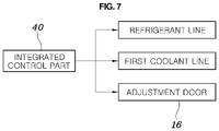
- FIG. 7 is a diagram illustrating an integrated control part of the thermal management system for the electric vehicle according to an embodiment of the present disclosure.
- vehicle or “vehicular” or other similar term as used herein is inclusive of motor vehicles in general such as passenger automobiles including sports utility vehicles (SUV), buses, trucks, various commercial vehicles, watercraft including a variety of boats and ships, aircraft, and the like, and includes hybrid vehicles, electric vehicles, plug-in hybrid electric vehicles, hydrogen-powered vehicles and other alternative fuel vehicles (e.g. fuels derived from resources other than petroleum).
- a hybrid vehicle is a vehicle that has two or more sources of power, for example both gasoline-powered and electric-powered vehicles.
- control logic of the present disclosure may be embodied as non-transitory computer readable media on a computer readable medium containing executable program instructions executed by a processor, controller or the like.
- Examples of computer readable media include, but are not limited to, ROM, RAM, compact disc (CD)-ROMs, magnetic tapes, floppy disks, flash drives, smart cards and optical data storage devices.
- the computer readable medium can also be distributed in network coupled computer systems so that the computer readable media is stored and executed in a distributed fashion, e.g., by a telematics server or a Controller Area Network (CAN).
- a telematics server or a Controller Area Network (CAN).
- CAN Controller Area Network
- FIG. 2 is a diagram illustrating a thermal management system for an electric vehicle according to an embodiment of the present disclosure
- FIG. 3 is a diagram illustrating an interior air conditioning part of the thermal management system for the electric vehicle according to an embodiment of the present disclosure
- FIGS. 4 to 6 are diagrams illustrating the thermal management system for the electric vehicle according to another embodiment of the present disclosure
- FIG. 7 is a diagram illustrating an integrated control part of the thermal management system for the electric vehicle according to an embodiment of the present disclosure.
- a thermal management system for an electric vehicle includes an interior air conditioning part 10 including an air inflow part 12 , an air discharge part 14 , a cooling core C, a heating core H arranged between the cooling core C and the air discharge part 14 , and an adjustment door 16 for selectively adjusting whether air having passed through the cooling core C flows into the heating core H; and a heat transfer line 20 having first and second sides connected to an electric part core and the heating core H, respectively, to be heat-transferable so that heat of an electric part 30 is transferred to the heating core H, thereby allowing the electric part 30 to dissipate the heat through the heating core H.
- the air inflow part 12 of the interior air conditioning part 10 may receive exterior air or interior air of the vehicle, and the air discharge part 14 may be connected with an interior space of the vehicle or an exterior of the vehicle.
- the interior air conditioning part 10 is provided.
- the interior air conditioning part 10 is arranged with the air inflow part 12 and the air discharge part 14 .
- the exterior air or the interior air of the vehicle flows into the interior air conditioning part 10 through the air inflow part 12 .
- the air discharge part 14 arranged in the interior air conditioning part 10 is connected with the interior space of the vehicle or the exterior of the vehicle. Therefore, the air flowing into the interior air conditioning part 10 through the air inflow part 12 may be discharged into the interior space of the vehicle or the exterior of the vehicle through the air discharge part 14 .
- the air discharge part may be connected with the interior space of the vehicle or the exterior of the vehicle through a duct I connected to the interior space of the vehicle and a duct U connected to the exterior of the vehicle.
- the duct I connected to the interior space of the vehicle is arranged in plural and the air having passed through the interior air conditioning part may be variously discharged into a seat back, a seat cushion, a roof vent, a floor part, or a windshield, etc., respectively.
- a door, etc. is arranged in the duct I to open and close each duct, and a mode in which each duct I may discharge may be performed variously.
- the air having passed through the interior air conditioning part may be immediately discharged into the exterior of the vehicle through the duct U connected with the exterior of the vehicle. Even in this case, a door, etc. may be arranged in the duct U to open and close the duct U.
- the interior air conditioning part 10 of the present disclosure is arranged with the cooling core C and the heating core H between the cooling core C and the air discharge part 14 .
- the cooling core C cools the exterior air or the interior air of the vehicle passing through the cooling core C during operation.
- the heating core H heats the air passing through the heating core H during operation.
- the present disclosure is arranged with an adjustment door 16 .
- the adjustment door 16 selectively adjusts whether the air having passed through the cooling core C flows into the heating core H. For example, as shown in FIG. 3 , the adjustment door 16 may allow the air having passed through the cooling core C to flow into the heating core H (path “A1”). Then, as shown in FIG. 4 , the adjustment door 16 may prevent the air having passed through the cooling core C from flowing into the heating core H. In this case, the air flowing into the interior air conditioning part 10 does not flow into the heating core H and is moved to the air discharge part (path “A2”). In addition, as shown in FIG.
- the adjustment door 16 may allow a part of the air having passed through the cooling core C to flow into the heating core H (path “A4”) and prevent the remainder from flowing into the heating core H (path “A3”). In this case, the cooled air and the heated air may be mixed and discharged into the interior space of the vehicle. Therefore, the adjustment door 16 opens and closes the heating core H to control the path through which the air moves inside the interior air conditioning part 10 .
- the adjustment door 16 may be arranged between the cooling core C and the heating core H.
- the position of the adjustment door 16 is not limited between the cooling core C and the heating core H, and it is apparent that the position of the adjustment door 16 may be arranged anywhere if it is a position capable of controlling the path through which the air inside the interior air conditioning part 10 as described above moves.
- the heat transfer line 20 has first and second sides connected to the electric part core and the heating core H, respectively, to be heat-transferable so that heat of the electric part 30 is transferred to the heating core H, thereby allowing the electric part 30 to dissipate the heat through the heating core H.
- the electric part 30 is a concept including a motor or an inverter, etc.
- the conventional electric vehicle has required the thermal management system having a separate radiator for heat-dissipating the electric part. Except for the case where the heating value of the electric part is maximized as in the rapid acceleration section, the heating value of the electric part was not large during most of the traveling time in the case such as the acceleration section or the fastest traveling.
- the conventional thermal management system for the electric vehicle is designed in preparation for the case where the heating value of the electric part for the electric vehicle is the highest, such that many separate parts are required and it is inefficient. Therefore, in order to solve the above problem, the present disclosure is arranged with the heat transfer line.
- the heat transfer line 20 has first and second sides connected to the electric part core and the heating core H, respectively, to be heat-transferable so that heat of the electric part 30 is transferred to the heating core H, thereby allowing the electric part 30 to dissipate the heat through the heating core H. Therefore, it is possible to dissipate the heat from the electric part 30 by using the heating core H arranged in the interior air conditioning part 10 , thereby adjusting the temperature of the interior space of the vehicle and adjusting the heat-dissipation of the electric part 30 . As a result, since one system may adjust the temperature of the interior space of the vehicle and the heat-dissipation of the electric part, the parts for the system are less than those for the conventional thermal management system for the electric vehicle. As a result, it is possible to reduce the cost for manufacturing the electric vehicle, and reduce the overall layout for the thermal management system as compared with the conventional electric vehicle.
- the electric part core may be a heat dissipating part arranged integrally with the electric part 30 , or may also be a heat dissipating part arranged separately from the electric part 30 to be heat-transferable.
- a motor, etc. is disposed in the electric part 30 of the right side thereof, and an oil cooler L serves as the electric part core, and the electric part 30 on the lower side thereof is connected with the heat transfer line 20 and the heat dissipating part coupled integrally with the electric part such as an inverter serves as the electric part core.
- refrigerant such as oil is circulated in a refrigerant line arranged with the oil cooler L through a third pump P 3 and the heat of the electric part 30 is transferred to the oil cooler L. Then, the heat of the oil cooler L is transferred to the heating core H through the heat transfer line 20 connected to the oil cooler L.
- the cooling core C may comprise an evaporator and is connected with the refrigerant line including a compressor E, a condenser D, and an expansion valve V.
- the refrigerant is circulated inside the refrigerant line.
- the refrigerant circulates the refrigerant line and flows into the cooling core C through the compressor E, the condenser D, and the expansion valve V to circulate a cooling cycle. Then, the air passing through the cooling core C, which is an evaporator, is cooled by heat-exchanging with the refrigerant inside the cooling core C.
- the heating core H may comprise a radiator and is connected to a first coolant line including a first pump P 1 and an electric heater T. Coolant flows inside the first coolant line, and the coolant is circulated through the first pump P 1 . The coolant is heated through the electric heater T, and heat-exchanged with the air passing through the heating core H in the heating core H that is a radiator. Therefore, the air passing through the heating core H is heated. Then, the heat generated by the heat-generation of the electric part 30 is dissipated from the heating core H, thereby utilizing the waste heat of the electric part 30 . Therefore, it is possible to utilize the waste heat of the electric part 30 , thereby increasing the thermal efficiency.
- the heat transfer line 20 of the present disclosure may comprise a heat pipe 20 a .
- the heating core H may be disposed above the electric part 30 with respect to a height direction of the vehicle.
- the heat of the electric part 30 is transferred only to the heating core H due to the heat transfer characteristic of the heat pipe 20 a . This is because the fluid in the liquid state inside the heat pipe 20 a is placed at the electric part 30 side disposed under the heating core H by gravity.
- the heat transfer line 20 comprises the heat pipe 20 a , thereby increasing the heat transfer rate from the electric part 30 to the heating core H.
- the heating core H is disposed above the electric part 30 , thereby preventing the heat of the heating core H from being transferred to the electric part 30 .
- the heat transfer line 20 comprises a second pump P 2 and a second coolant line connected to the heating core H, and the electric part core is disposed in the second coolant line so that the heat of the electric part 30 may be transferred to the heating core H.
- the coolant flows inside the second coolant line through the second pump P 2 to recover the heat of the electric part 30 and transfer it to the heating core H.
- the flow path of the first coolant line and the flow path of the second coolant line may be separately disposed in the heating core H to heat-exchange with the air passing through the heating core H, respectively or the flow path of the first coolant line and the flow path of the second coolant line are superimposed to heat-exchange with the air passing through the heating core H.
- a thermal management system for an electric vehicle further includes a heat exchanger X arranged between the cooling core C and the heating core H of the interior air conditioning part 10 , and the heat transfer line 20 has first and second sides connected to the electric part core and the heat exchanger X, respectively, to be heat-transferable so that the heat of the electric part 30 is transferred to the heat exchanger X, thereby allowing the electric part to dissipate the heat through the heat exchanger X.
- the heat exchanger X As an embodiment of the heat exchanger X, a radiator, etc. may be utilized, and the air flowing into the heat exchanger X is heated by heat-exchanging with the heat exchanger X. Therefore, the heat of the electric part 30 may be dissipated through the heat exchanger X. Then, the air having passed through the heat exchanger X may be heated to be discharged into the interior space of the vehicle.
- a flow space F is formed at the side of the heating core H of the interior air conditioning part 10 , and according to control of the adjustment door 16 , the air may pass through the cooling core C and then flow to the air discharge part 14 only through the flow space F, the air may pass through the cooling core C and then flow to the air discharge part 14 only through the heating core H, or the air may pass through the cooling core C and then flow to the air discharge part 14 through the flow space F and the heating core H.
- the air flowing into through the air inflow part 12 passes through the cooling core C and then flows to the air discharge part 14 only through the flow space F (path “A2”). In this case, the air does not pass through the heating core H. Then, when the adjustment door 16 is disposed as shown in FIG. 3 , the air flowing into through the air inflow part 12 passes through the cooling core C and then flows to the air discharge part 14 only through the heating core H (path “A1”). In this case, the air does not pass through the flow space F. In addition, when the adjustment door 16 is disposed as shown in FIG.
- the air flowing into through the air inflow part 12 may pass through the cooling core C and then flow to the air discharge part 14 through the flow space F and the heating core H (paths “A3” and “A4”). Therefore, the air in various modes may be discharged into the interior space of the vehicle according to control of the passenger.
- the air cooled only through the cooling core may be discharged into the interior space of the vehicle
- the air heated by using only the heating core without operating the cooling core may be discharged into the interior space of the vehicle
- the air heated and dehumidified by using the cooling core and the heating core may be discharged into the interior space of the vehicle, or as shown in FIG. 5
- the air heated and the air cooled by differentiating the paths (“A3” and “A4”) of the air inside the interior air conditioning part may be mixed to be also discharged into the interior space of the vehicle.
- the cooling core C comprises an evaporator and is arranged in the refrigerant line including the compressor E, the condenser D, and the expansion valve V, and the present disclosure may further include an integrated control part 40 for controlling the operation of the refrigerant line or the first coolant line and the operation of the adjustment door 16 .
- the integrated control part 40 may control the adjustment door 16 so that the air having passed through the cooling core C flows into the heating core H.
- the integrated control part 40 is arranged with a thermal sensing sensor capable of measuring the temperature or the heating value of the electric part 30 . Therefore, it is possible to control the adjustment door so that the air having passed through the cooling core C flows into the heating core H when the electric part 30 generates heat and the required cooling amount is a certain value or more, thereby heat-dissipating the electric part 30 through the heating core H.
- the adjustment door 16 is disposed to close the flow space F.
- the refrigerant line is operated and the refrigerant cooled by the cooling core C is supplied, and the cooled refrigerant may be heat-exchanged with the air flowing into the interior air conditioning part 10 , thereby discharging the cooled air into the interior space of the vehicle.
- the first coolant line is not operated. Therefore, it is possible to discharge the cooled air into the interior space of the vehicle, and at the same time, dissipate the heat the electric part 30 . Then, since the cooled air flows into the heating core H, the electric part 30 may further dissipate the heat.
- the integrated control part 40 may control the adjustment door 16 so that the air having passed through the cooling core C flows into the heating core H, and control so that the first coolant line is operated.
- the coolant heated through the electric heater T flows into the heating core H through the first coolant line, and the coolant flowing into the heating core H heat-exchanges with the air flowing into the interior air conditioning part 10 . Therefore, the air flowing into the interior air conditioning part 10 is heated and the heated air is discharged into the interior space of the vehicle.
- the heating core H since the heating core H has been disposed above the electric part 30 , the heat of the heated coolant flowing into the heating core H is not transferred to the electric part 30 due to the heat transfer characteristic of the heat pipe. Meanwhile, even in this case, when the heating value of the electric part 30 instantaneously changes to a certain value or more, the integrated control part 40 may control the first refrigerant line not to operate. In this case, the heating core H is used only for heat-dissipation of the electric part 30 . This is a mode applied when the heating value of the electric part 30 instantaneously changes to a certain value or more, such as when the electric car is rapidly accelerated. Then, the heat of the electric part 30 is dissipated through the heating core H and the air having passed through the heating core H may be heated, thereby continuously discharging the heated air into the interior space of the vehicle.
- the integrated control part 40 may control the adjustment door 16 so that the air having passed through the cooling core C does not flow into the heating core H, and control so that the refrigerant line is operated.
- the air having passed through the cooling core C is cooled and discharged into the interior space of the vehicle.
- the heating value of the electric part 30 is not large, the heat of the electric part 30 may be sufficiently dissipated even if air does not flow into the heating core H.
- the integrated control part 40 may operate both the first coolant line and the refrigerant line.
- the air having passed through the cooling core C is cooled and dehumidified, and then passes through the heating core H to be heated. Therefore, the heated and dehumidified air may be discharged into the interior space of the vehicle.
- thermo management system for the electric vehicle of the present disclosure it is possible to adjust the temperature of the interior space of the vehicle, and cool the electric part.
- waste heat of the electric part may be used, it is possible to increase the thermal efficiency of the electric vehicle.
Landscapes
- Engineering & Computer Science (AREA)
- Physics & Mathematics (AREA)
- Thermal Sciences (AREA)
- Mechanical Engineering (AREA)
- Life Sciences & Earth Sciences (AREA)
- Sustainable Development (AREA)
- Sustainable Energy (AREA)
- Chemical & Material Sciences (AREA)
- Combustion & Propulsion (AREA)
- Air-Conditioning For Vehicles (AREA)
Abstract
Description
Claims (13)
Applications Claiming Priority (2)
| Application Number | Priority Date | Filing Date | Title |
|---|---|---|---|
| KR1020190048225A KR20200125791A (en) | 2019-04-25 | 2019-04-25 | Thermal management system for electronic vehicle |
| KR10-2019-0048225 | 2019-04-25 |
Publications (2)
| Publication Number | Publication Date |
|---|---|
| US20200338955A1 US20200338955A1 (en) | 2020-10-29 |
| US11413933B2 true US11413933B2 (en) | 2022-08-16 |
Family
ID=72921173
Family Applications (1)
| Application Number | Title | Priority Date | Filing Date |
|---|---|---|---|
| US16/591,130 Active 2040-03-28 US11413933B2 (en) | 2019-04-25 | 2019-10-02 | Thermal management system for electric vehicle |
Country Status (2)
| Country | Link |
|---|---|
| US (1) | US11413933B2 (en) |
| KR (1) | KR20200125791A (en) |
Families Citing this family (1)
| Publication number | Priority date | Publication date | Assignee | Title |
|---|---|---|---|---|
| US20220310430A1 (en) * | 2021-03-26 | 2022-09-29 | Taiwan Semiconductor Manufacturing Company Ltd. | Control system for wafer transport vehicle and method for operating the same |
Citations (36)
| Publication number | Priority date | Publication date | Assignee | Title |
|---|---|---|---|---|
| US5528900A (en) * | 1994-06-01 | 1996-06-25 | Prasad; Mukesh | Instant automobile cooling system |
| US20060137853A1 (en) * | 2003-02-20 | 2006-06-29 | Valeo Climatisation | Ventilation/heating and/or air conditioning device for the passenger compartment of a motor vehicle with simultaneous cooling of air and coolant |
| US7096935B2 (en) * | 2002-05-22 | 2006-08-29 | Denso Corporation | Vehicle power supply control apparatus |
| US7159651B2 (en) * | 2003-09-26 | 2007-01-09 | Denso Corporation | Air conditioner for vehicle use |
| US20080006394A1 (en) * | 2006-07-10 | 2008-01-10 | Exxonmobil Research And Engineering Company | Heat pipe structure |
| US20110000241A1 (en) * | 2009-07-02 | 2011-01-06 | Ferrari S.P.A. | Electric traction vehicle with cooling by refrigeration cycle |
| US20110120146A1 (en) * | 2009-11-25 | 2011-05-26 | Denso Corporation | Air Conditioner for vehicle |
| DE102010037128A1 (en) * | 2010-08-24 | 2012-03-01 | Webasto Ag | Heating device for use in vehicle .e. road vehicle, for heating fuel-powered vehicle interior part, has heat pipe whose one side is arranged at outer side of passenger cabin and another side is arranged within cabin |
| US20120079835A1 (en) * | 2010-10-04 | 2012-04-05 | Hyundai Motor Company | Auxiliary air conditioner for vehicle |
| US20130228320A1 (en) * | 2012-03-02 | 2013-09-05 | Mohamed Younes El-Saghir Selim | Heat Transfer Device For Reducing Heat Inside Vehicles And A Method Of Determining An Optimal Structure Thereof |
| US20140182319A1 (en) * | 2012-12-28 | 2014-07-03 | Arlon J. Hunt | Thermal energy storage for temperature regulation in electric vehicles |
| KR101416357B1 (en) | 2012-09-07 | 2014-07-08 | 현대자동차 주식회사 | Heat pump system for vehicle |
| KR101436960B1 (en) | 2012-11-20 | 2014-09-16 | 대한칼소닉주식회사 | Electric vehicle battery temperature management system conjunction with the HVAC system and its operating method |
| US9517677B2 (en) * | 2010-06-16 | 2016-12-13 | Nissan Motor Co., Ltd. | Vehicle air conditioning system |
| WO2017003504A1 (en) * | 2015-06-30 | 2017-01-05 | Faraday&Future Inc. | Heat pipe for vehicle energy-storage systems |
| US20170080778A1 (en) * | 2014-05-08 | 2017-03-23 | Sanden Holdings Corporation | Vehicle air conditioning device |
| US20170096048A1 (en) * | 2015-09-09 | 2017-04-06 | International Truck Intellectual Property Company, Llc | Vehicle climate control system |
| US9643469B2 (en) * | 2012-02-02 | 2017-05-09 | Denso Corporation | Vehicle thermal management system |
| US20170129309A1 (en) * | 2014-07-31 | 2017-05-11 | Hanon Systems | Heat pump system for vehicle |
| US20170151857A1 (en) * | 2011-12-09 | 2017-06-01 | Sanden Holdings Corporation | Vehicle air conditioning apparatus |
| US20170274725A1 (en) * | 2014-09-19 | 2017-09-28 | Sanden Holdings Corporation | Vehicle air conditioner device |
| US20170282689A1 (en) * | 2014-09-24 | 2017-10-05 | Sanden Holdings Corporation | Air-conditioning apparatus for vehicle |
| US20170326943A1 (en) * | 2014-12-04 | 2017-11-16 | Sanden Holdings Corporation | Vehicle air conditioner device |
| US20180065451A1 (en) * | 2015-03-16 | 2018-03-08 | Hanon Systems | Vehicular heat pump system |
| KR101875651B1 (en) | 2016-09-13 | 2018-07-06 | 현대자동차 주식회사 | Heat pump system for vehicle |
| US20190070924A1 (en) * | 2017-09-07 | 2019-03-07 | Tesla, Inc. | Optimal source electric vehicle heat pump with extreme temperature heating capability and efficient thermal preconditioning |
| US20190168579A1 (en) * | 2016-07-22 | 2019-06-06 | Hanon Systems | Air conditioning system for vehicle and method for controlling same |
| US20190225050A1 (en) * | 2014-01-21 | 2019-07-25 | Hanon Systems | Heat pump system for vehicle |
| US20200086714A1 (en) * | 2018-09-14 | 2020-03-19 | Ford Global Technologies, Llc | Method and system for heating a vehicle |
| US20200122544A1 (en) * | 2017-04-18 | 2020-04-23 | Sanden Automotive Climate Systems Corporation | Vehicular air conditioning device |
| US20200130466A1 (en) * | 2018-10-26 | 2020-04-30 | Honda Motor Co., Ltd. | Vehicle air conditioning apparatus |
| US20200130467A1 (en) * | 2018-10-26 | 2020-04-30 | Honda Motor Co., Ltd. | Vehicle air conditioning apparatus |
| US10752078B2 (en) * | 2013-12-06 | 2020-08-25 | Denso Corporation | Heat transfer device |
| US20210108841A1 (en) * | 2018-06-08 | 2021-04-15 | Denso Corporation | Refrigeration cycle device for vehicle |
| US20210245572A1 (en) * | 2017-11-07 | 2021-08-12 | Hanon Systems | Thermal management system |
| US20210252941A1 (en) * | 2018-11-08 | 2021-08-19 | Denso Corporation | Vehicle air conditioner |
-
2019
- 2019-04-25 KR KR1020190048225A patent/KR20200125791A/en not_active Application Discontinuation
- 2019-10-02 US US16/591,130 patent/US11413933B2/en active Active
Patent Citations (38)
| Publication number | Priority date | Publication date | Assignee | Title |
|---|---|---|---|---|
| US5528900A (en) * | 1994-06-01 | 1996-06-25 | Prasad; Mukesh | Instant automobile cooling system |
| US7096935B2 (en) * | 2002-05-22 | 2006-08-29 | Denso Corporation | Vehicle power supply control apparatus |
| US20060137853A1 (en) * | 2003-02-20 | 2006-06-29 | Valeo Climatisation | Ventilation/heating and/or air conditioning device for the passenger compartment of a motor vehicle with simultaneous cooling of air and coolant |
| US7159651B2 (en) * | 2003-09-26 | 2007-01-09 | Denso Corporation | Air conditioner for vehicle use |
| US20080006394A1 (en) * | 2006-07-10 | 2008-01-10 | Exxonmobil Research And Engineering Company | Heat pipe structure |
| US20110000241A1 (en) * | 2009-07-02 | 2011-01-06 | Ferrari S.P.A. | Electric traction vehicle with cooling by refrigeration cycle |
| US8973386B2 (en) * | 2009-07-02 | 2015-03-10 | Ferrari S.P.A. | Electric traction vehicle with cooling by refrigeration cycle |
| US20110120146A1 (en) * | 2009-11-25 | 2011-05-26 | Denso Corporation | Air Conditioner for vehicle |
| US9517677B2 (en) * | 2010-06-16 | 2016-12-13 | Nissan Motor Co., Ltd. | Vehicle air conditioning system |
| DE102010037128A1 (en) * | 2010-08-24 | 2012-03-01 | Webasto Ag | Heating device for use in vehicle .e. road vehicle, for heating fuel-powered vehicle interior part, has heat pipe whose one side is arranged at outer side of passenger cabin and another side is arranged within cabin |
| US20120079835A1 (en) * | 2010-10-04 | 2012-04-05 | Hyundai Motor Company | Auxiliary air conditioner for vehicle |
| US20170151857A1 (en) * | 2011-12-09 | 2017-06-01 | Sanden Holdings Corporation | Vehicle air conditioning apparatus |
| US9643469B2 (en) * | 2012-02-02 | 2017-05-09 | Denso Corporation | Vehicle thermal management system |
| US20130228320A1 (en) * | 2012-03-02 | 2013-09-05 | Mohamed Younes El-Saghir Selim | Heat Transfer Device For Reducing Heat Inside Vehicles And A Method Of Determining An Optimal Structure Thereof |
| KR101416357B1 (en) | 2012-09-07 | 2014-07-08 | 현대자동차 주식회사 | Heat pump system for vehicle |
| KR101436960B1 (en) | 2012-11-20 | 2014-09-16 | 대한칼소닉주식회사 | Electric vehicle battery temperature management system conjunction with the HVAC system and its operating method |
| US20140182319A1 (en) * | 2012-12-28 | 2014-07-03 | Arlon J. Hunt | Thermal energy storage for temperature regulation in electric vehicles |
| US10752078B2 (en) * | 2013-12-06 | 2020-08-25 | Denso Corporation | Heat transfer device |
| US20190225050A1 (en) * | 2014-01-21 | 2019-07-25 | Hanon Systems | Heat pump system for vehicle |
| US20190255911A1 (en) * | 2014-05-08 | 2019-08-22 | Sanden Holdings Corporation | Vehicle air conditioning device |
| US20170080778A1 (en) * | 2014-05-08 | 2017-03-23 | Sanden Holdings Corporation | Vehicle air conditioning device |
| US20170129309A1 (en) * | 2014-07-31 | 2017-05-11 | Hanon Systems | Heat pump system for vehicle |
| US20170274725A1 (en) * | 2014-09-19 | 2017-09-28 | Sanden Holdings Corporation | Vehicle air conditioner device |
| US20170282689A1 (en) * | 2014-09-24 | 2017-10-05 | Sanden Holdings Corporation | Air-conditioning apparatus for vehicle |
| US20170326943A1 (en) * | 2014-12-04 | 2017-11-16 | Sanden Holdings Corporation | Vehicle air conditioner device |
| US20180065451A1 (en) * | 2015-03-16 | 2018-03-08 | Hanon Systems | Vehicular heat pump system |
| WO2017003504A1 (en) * | 2015-06-30 | 2017-01-05 | Faraday&Future Inc. | Heat pipe for vehicle energy-storage systems |
| US20170096048A1 (en) * | 2015-09-09 | 2017-04-06 | International Truck Intellectual Property Company, Llc | Vehicle climate control system |
| US20190168579A1 (en) * | 2016-07-22 | 2019-06-06 | Hanon Systems | Air conditioning system for vehicle and method for controlling same |
| KR101875651B1 (en) | 2016-09-13 | 2018-07-06 | 현대자동차 주식회사 | Heat pump system for vehicle |
| US20200122544A1 (en) * | 2017-04-18 | 2020-04-23 | Sanden Automotive Climate Systems Corporation | Vehicular air conditioning device |
| US20190070924A1 (en) * | 2017-09-07 | 2019-03-07 | Tesla, Inc. | Optimal source electric vehicle heat pump with extreme temperature heating capability and efficient thermal preconditioning |
| US20210245572A1 (en) * | 2017-11-07 | 2021-08-12 | Hanon Systems | Thermal management system |
| US20210108841A1 (en) * | 2018-06-08 | 2021-04-15 | Denso Corporation | Refrigeration cycle device for vehicle |
| US20200086714A1 (en) * | 2018-09-14 | 2020-03-19 | Ford Global Technologies, Llc | Method and system for heating a vehicle |
| US20200130466A1 (en) * | 2018-10-26 | 2020-04-30 | Honda Motor Co., Ltd. | Vehicle air conditioning apparatus |
| US20200130467A1 (en) * | 2018-10-26 | 2020-04-30 | Honda Motor Co., Ltd. | Vehicle air conditioning apparatus |
| US20210252941A1 (en) * | 2018-11-08 | 2021-08-19 | Denso Corporation | Vehicle air conditioner |
Also Published As
| Publication number | Publication date |
|---|---|
| CN111845249A (en) | 2020-10-30 |
| US20200338955A1 (en) | 2020-10-29 |
| KR20200125791A (en) | 2020-11-05 |
Similar Documents
| Publication | Publication Date | Title |
|---|---|---|
| JP7232638B2 (en) | Temperature control system for electric vehicles | |
| US9067475B1 (en) | Method and system of heating cabin of hybrid electric vehicle | |
| JP2936960B2 (en) | Heat pump type air conditioner for vehicles | |
| JP6394683B2 (en) | Transportation refrigeration equipment | |
| CN107639996B (en) | Vehicle auxiliary heating, ventilating and air conditioning system using coolant loop for cooling component and vehicle interior | |
| CN114312205A (en) | Thermal management system, control method of thermal management system and electric automobile | |
| CN111129663B (en) | Vehicle-mounted thermal management system and vehicle | |
| CN112297758A (en) | HVAC system for a vehicle | |
| US11413933B2 (en) | Thermal management system for electric vehicle | |
| JP2005306300A (en) | Air conditioner for vehicle | |
| US11707966B2 (en) | Heat request arbitration device, heat request arbitration method, non-transitory storage medium, and vehicle | |
| US11390135B2 (en) | Thermal management system for vehicle | |
| CN118163563A (en) | Thermal management system | |
| CN115723632B (en) | Temperature control device and temperature control method for electric automobile | |
| CN111845249B (en) | Thermal management system for electric vehicle | |
| US20220396117A1 (en) | Cooling System for Vehicle | |
| US11606006B2 (en) | System for overcooling drive motor and method for controlling the same | |
| CN106494181B (en) | Vehicle HVAC system with auxiliary coolant loop | |
| CN113412397B (en) | Air conditioner for vehicle | |
| JPH10114215A (en) | Air conditioning controller for automobile | |
| JP2019108030A (en) | Vehicular air conditioner | |
| US20220305885A1 (en) | Integrated thermal management circuit for vehicle | |
| US11724567B2 (en) | Method of controlling automotive heating, ventilation, and air conditioning system | |
| WO2023203943A1 (en) | Vehicular air conditioning device | |
| CN221698563U (en) | Vehicle-mounted refrigerator and vehicle |
Legal Events
| Date | Code | Title | Description |
|---|---|---|---|
| AS | Assignment |
Owner name: HYUNDAI MOTOR COMPANY, KOREA, REPUBLIC OF Free format text: ASSIGNMENT OF ASSIGNORS INTEREST;ASSIGNORS:LEE, SANG SHIN;OH, MAN JU;CHUNG, SO LA;AND OTHERS;REEL/FRAME:050605/0681 Effective date: 20190826 Owner name: KIA MOTORS CORPORATION, KOREA, REPUBLIC OF Free format text: ASSIGNMENT OF ASSIGNORS INTEREST;ASSIGNORS:LEE, SANG SHIN;OH, MAN JU;CHUNG, SO LA;AND OTHERS;REEL/FRAME:050605/0681 Effective date: 20190826 |
|
| FEPP | Fee payment procedure |
Free format text: ENTITY STATUS SET TO UNDISCOUNTED (ORIGINAL EVENT CODE: BIG.); ENTITY STATUS OF PATENT OWNER: LARGE ENTITY |
|
| STPP | Information on status: patent application and granting procedure in general |
Free format text: DOCKETED NEW CASE - READY FOR EXAMINATION |
|
| STPP | Information on status: patent application and granting procedure in general |
Free format text: NON FINAL ACTION MAILED |
|
| STPP | Information on status: patent application and granting procedure in general |
Free format text: RESPONSE TO NON-FINAL OFFICE ACTION ENTERED AND FORWARDED TO EXAMINER |
|
| STPP | Information on status: patent application and granting procedure in general |
Free format text: NOTICE OF ALLOWANCE MAILED -- APPLICATION RECEIVED IN OFFICE OF PUBLICATIONS |
|
| STPP | Information on status: patent application and granting procedure in general |
Free format text: PUBLICATIONS -- ISSUE FEE PAYMENT VERIFIED |
|
| STCF | Information on status: patent grant |
Free format text: PATENTED CASE |