US11409017B2 - Metal detector coil configuration to eliminate orientation effect - Google Patents
Metal detector coil configuration to eliminate orientation effect Download PDFInfo
- Publication number
- US11409017B2 US11409017B2 US17/254,791 US201917254791A US11409017B2 US 11409017 B2 US11409017 B2 US 11409017B2 US 201917254791 A US201917254791 A US 201917254791A US 11409017 B2 US11409017 B2 US 11409017B2
- Authority
- US
- United States
- Prior art keywords
- detection
- coils
- metal
- aperture
- flow path
- Prior art date
- Legal status (The legal status is an assumption and is not a legal conclusion. Google has not performed a legal analysis and makes no representation as to the accuracy of the status listed.)
- Active
Links
Images


Classifications
-
- G—PHYSICS
- G01—MEASURING; TESTING
- G01V—GEOPHYSICS; GRAVITATIONAL MEASUREMENTS; DETECTING MASSES OR OBJECTS; TAGS
- G01V3/00—Electric or magnetic prospecting or detecting; Measuring magnetic field characteristics of the earth, e.g. declination, deviation
- G01V3/08—Electric or magnetic prospecting or detecting; Measuring magnetic field characteristics of the earth, e.g. declination, deviation operating with magnetic or electric fields produced or modified by objects or geological structures or by detecting devices
- G01V3/10—Electric or magnetic prospecting or detecting; Measuring magnetic field characteristics of the earth, e.g. declination, deviation operating with magnetic or electric fields produced or modified by objects or geological structures or by detecting devices using induction coils
- G01V3/104—Electric or magnetic prospecting or detecting; Measuring magnetic field characteristics of the earth, e.g. declination, deviation operating with magnetic or electric fields produced or modified by objects or geological structures or by detecting devices using induction coils using several coupled or uncoupled coils
- G01V3/105—Electric or magnetic prospecting or detecting; Measuring magnetic field characteristics of the earth, e.g. declination, deviation operating with magnetic or electric fields produced or modified by objects or geological structures or by detecting devices using induction coils using several coupled or uncoupled coils forming directly coupled primary and secondary coils or loops
- G01V3/107—Electric or magnetic prospecting or detecting; Measuring magnetic field characteristics of the earth, e.g. declination, deviation operating with magnetic or electric fields produced or modified by objects or geological structures or by detecting devices using induction coils using several coupled or uncoupled coils forming directly coupled primary and secondary coils or loops using compensating coil or loop arrangements
-
- G—PHYSICS
- G01—MEASURING; TESTING
- G01V—GEOPHYSICS; GRAVITATIONAL MEASUREMENTS; DETECTING MASSES OR OBJECTS; TAGS
- G01V3/00—Electric or magnetic prospecting or detecting; Measuring magnetic field characteristics of the earth, e.g. declination, deviation
- G01V3/08—Electric or magnetic prospecting or detecting; Measuring magnetic field characteristics of the earth, e.g. declination, deviation operating with magnetic or electric fields produced or modified by objects or geological structures or by detecting devices
- G01V3/10—Electric or magnetic prospecting or detecting; Measuring magnetic field characteristics of the earth, e.g. declination, deviation operating with magnetic or electric fields produced or modified by objects or geological structures or by detecting devices using induction coils
- G01V3/104—Electric or magnetic prospecting or detecting; Measuring magnetic field characteristics of the earth, e.g. declination, deviation operating with magnetic or electric fields produced or modified by objects or geological structures or by detecting devices using induction coils using several coupled or uncoupled coils
- G01V3/108—Electric or magnetic prospecting or detecting; Measuring magnetic field characteristics of the earth, e.g. declination, deviation operating with magnetic or electric fields produced or modified by objects or geological structures or by detecting devices using induction coils using several coupled or uncoupled coils the emitter and the receiver coils or loops being uncoupled by positioning them perpendicularly to each other
Definitions
- Metal detectors are used to detect metals and/or metal contaminants in product streams. Metal detectors detect metal as they pass through a plane of detection defined by the orientation of detection coils within the system. There are limitations in the ability of various metal detector systems to detect metals based on the orientation of the metal object as it passes through the plane of detection. What is needed is a solution that eliminates or reduces the orientation effect that prior art metal detectors are prone to.
- a system for metal detection comprising a single aperture that further comprises two or more sets of detection coils that surround the perimeter of the aperture.
- a flow path of materials passes through the aperture.
- Each set of detection coils comprises a transmitter coil and two receiver coils, with the transmitter coil located between the two receiver coils.
- Each set of detection coils is at a different angle relative to the flow path.
- the aperture could comprise three sets of detection coils that surround the perimeter of the aperture.
- one set of detection coils is at an angle of 45 degrees relative to the flow path. In some embodiments, one set of detection coils is at an angle of 135 degrees relative to the flow path.
- the flow path is one of a conveyor belt, a liquid line, or free-falling material.
- the aperture may be circular or a polygon. In various embodiments, the detection coils operate in the range of 1 kHz to 1 MHz. Each set of detection coils may be operated in a different detection frequency or in the same detection frequency.
- FIG. 1 shows a simplified schematic of a prior art metal detection system
- FIG. 2 shows a simplified schematic of the principle of operation of metal detection systems
- FIG. 3 depicts a metal contaminant passing through a detection plane in various configurations
- FIG. 4 depicts a simplified schematic of a prior art metal detection system comprising two separate metal detection systems with two apertures at different angles to the material flow path;
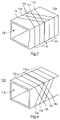
- FIG. 5 is a simplified schematic of an embodiment of the metal detection system having two sets of detection coils
- FIG. 6 is a simplified schematic of another embodiment of the metal detection system having two sets of detection coils
- FIG. 7 depicts a metal contaminant passing through a detection plane in various configurations
- FIG. 8 depicts a metal contaminant passing through a detection plane in various configurations.
- FIG. 9 is a simplified schematic of another embodiment of the metal detection system having three sets of detection coils.
- FIG. 1 shows a simplified schematic of a prior art metal detection system 10 .
- the system comprises an aperture 12 through which a flow path of materials passes through.
- a single set of detection coils 14 surrounds the perimeter of the aperture 12 .
- the set of detection coils 14 comprise a transmitter coil 16 (also called an oscillator coil) and two receiver coils 18 , with the transmitter coil 16 located between the two receiver coils 18 .
- FIG. 2 illustrates the basic operating principle of the type of metal detector to which this disclosure applies.
- a single voltage is driven through the transmitter coil 16 by an oscillator (not shown).
- the two receiver coils 18 are located on a common axis with the transmitter coil 16 and are coupled into the electromagnetic field of the transmitter coil 18 in such a manner that the system is in balance and the induced voltages in the two receiver coils 16 cancel.
- Material to be screened that passes through the aperture 12 creates a distortion in the electromagnetic field if there is any metal passing along with the material in the flow path through the aperture 12 . This distortion results in a difference in the induced voltages in the two secondary coils.
- the voltage difference is amplified, digitized, and filtered to extract detection information that is used to decide whether the signal represents metal or the user's product. If the signal represents the user's product, it is ignored. If it represents metal that exceeds a pre-set sensitivity level, the detector generates a detection signal that initiates reject and/or alarm actions.
- metal detectors typically have more difficulty detecting the contaminant in one orientation than in other orientations. For example, if a wire 22 passes through the metal detector with its long dimension parallel to the detection plane 20 of the detector coil, it may produce a significantly larger signal than if the same wire 22 passed through in an orientation perpendicular to the detection plane 20 of the detector coil. This is referred to as the “orientation effect,” and it occurs because the detection signal is related to the area of eddy current loops which are developed in the wire 22 .
- the orientation effect is referred to as the orientation effect
- FIG. 3 ( a )-( d ) shows a cylindrical contaminant wire 22 passing through the detection plane 20 at several angles
- FIG. 3 ( a 1 )-( d 1 ) shows the corresponding cross-sectional areas of the wire 22 intersecting the detection plane 20 .
- a metal contaminant 22 type develops eddy current loops parallel to the detection plane 20 of the detector coils, they produce their largest signal in orientation shown in FIG. 3( a ) , because that gives the largest area for the eddy current loops as shown in FIG. 3 ( a 1 ).
- the contaminant 22 orientation shown in FIG. 3 ( d ) has the smallest cross-sectional area shown in FIG. 3 ( d 1 ), thus producing the smallest signal.
- FIG. 3 ( d ) is the best case for detection sensitivity.
- Metal detector sensitivity is usually specified based on detecting a metal sphere, which has no orientation effect.
- the cross-sectional area parallel to the plane is equal to the area perpendicular to the plane, and the cross-section is always the same regardless of rotation of the sphere.
- the smallest sphere (of a given metal type) which is detectable by a given metal detector is called the “rated metal sphere” for that detector and metal type.
- a wire can arrive at the detector in any random orientation, so assuming the worst case, and the sensitivity for wires must be specified based on the diameter of the wire, regardless of length. Wires with a diameter greater than or equal to the rated metal sphere diameter will typically be detectable even in the worst orientation. A smaller-diameter wire, even if relatively large compared to the rated metal sphere size, has a risk of passing through without being detected.
- FIG. 4 shows an example of a prior art metal detector 10 installations using two separate metal detectors 10 , installed on the same conveyor line 24 on which a will material stream pass through.
- the metal detectors 10 are oriented at different angles relative to the conveyor line 24 .
- This has several disadvantages: it requires two complete metal detectors 10 ; it requires a longer conveyor line 24 system; in order to be able to be placed at an angle, the metal detectors 10 must be much wider than the conveyor line 24 ; it assumes that the wire does not change orientation while traveling between the two metal detectors 10 ; and with two metal detectors 10 it still does not completely eliminate orientation effect for metal types which have a worst case parallel to the coil, as explained later.
- FIG. 5 shows a simplified schematic of metal detector 10 a disclosed herein that addresses some of the limitations of the prior art systems.
- the system comprises an aperture 12 a through which a flow path of materials passes through.
- Two sets of detection coils 14 a surrounds the perimeter of the aperture 12 a .
- Each set of detection coils 14 a comprises a transmitter coil 16 a and two receiver coils 18 a , with the transmitter coil 16 a located between the two receiver coils 18 a .
- the detector coils 14 a are crossed on the top and bottom of the aperture 12 a .
- the aperture 12 a is shown as a having a rectangular opening in the figures, but it could be any shape required by the application such as any other polygon or a circle.
- the flow path of material that passes through the aperture 12 a may be a conveyor belt, a liquid line, or free-falling material.
- the system presented herein comprises two sets of metal detection coils 14 a within one metal detector 10 a housing.
- Each set of detection coils 14 a comprises a transmitter coil 16 a and two receiver coils 18 a , all parallel to each other. However, each set of detection coils 14 a is at a different angle relative to the direction of material travel through the aperture 12 a .
- the detection coils 14 a operate in a detection frequency in the range of 1 kHz to 1 MHz.
- the separate sets of detection coils 14 a are operated preferably at different detection frequencies, but it is possible they could be operated at the same detection frequency.
- the separate transmitter coils 16 a interfere with each other if there is mutual inductance coupling each transmitter coil 16 a , so the transmitter coils 16 a must be separated by a great enough angle to reduce this mutual inductance to an acceptable level.
- a 90° angle between each detection coil 14 a system reduces the mutual inductance to the minimum possible. Other angles are possible to reduce interference from each other, but a large angle (ideally 90°) is still desirable, for the maximum reduction of orientation effect.
- Embodiments where one set of detection coils is at an angle of 45° relative to the flow path have found to be effective.
- Embodiments where one set of detection coils is at an angle of 135° relative to the flow path have also found to be effective.
- using a large angle has a disadvantage of requiring a larger metal detector (i.e., a longer tunnel in the direction of product travel).
- FIG. 6 shows another embodiment of the metal detection system 10 b having two sets of detection coils 14 b in which the detector coils 14 b are crossed on the sides of the aperture.
- metal contaminants 22 are simultaneously subjected to detection planes 20 from more than one angle. So, if the contaminant 22 is in the worst orientation for detection at one detection plane 20 , it can be in a more favorable orientation for the other detection plane 20 .
- two sets of detection planes 20 are enough. The two sets of detections coils form intersecting detection planes 20 as shown in FIGS. 7 ( a )-( b ) and ( c )-( d ) .
- a wire contaminant 22 in any orientation cannot be perpendicular to both detection planes 20 .
- FIG. 8 ( a )-( b ) shows there would still be one orientation at which a contaminant wire 22 could be parallel to two detection planes 20 , so a third detection plane 20 as shown in FIG. 8 ( c ) is needed.
- FIG. 9 shows an embodiment of the metal detection system 10 c having three sets of detection coils 14 c for three different intersecting angles of detection planes. Embodiments with four sets of detection coils are possible but would have limited utility for eliminating orientation effects since all orientations are able to be handled by three sets of detection coils.
Abstract
Description
Claims (9)
Priority Applications (1)
| Application Number | Priority Date | Filing Date | Title |
|---|---|---|---|
| US17/254,791 US11409017B2 (en) | 2018-06-20 | 2019-06-20 | Metal detector coil configuration to eliminate orientation effect |
Applications Claiming Priority (3)
| Application Number | Priority Date | Filing Date | Title |
|---|---|---|---|
| US201862687298P | 2018-06-20 | 2018-06-20 | |
| PCT/US2019/038209 WO2019246378A1 (en) | 2018-06-20 | 2019-06-20 | Metal detector coil configuration to eliminate orientation effect |
| US17/254,791 US11409017B2 (en) | 2018-06-20 | 2019-06-20 | Metal detector coil configuration to eliminate orientation effect |
Publications (2)
| Publication Number | Publication Date |
|---|---|
| US20210263181A1 US20210263181A1 (en) | 2021-08-26 |
| US11409017B2 true US11409017B2 (en) | 2022-08-09 |
Family
ID=68984329
Family Applications (1)
| Application Number | Title | Priority Date | Filing Date |
|---|---|---|---|
| US17/254,791 Active US11409017B2 (en) | 2018-06-20 | 2019-06-20 | Metal detector coil configuration to eliminate orientation effect |
Country Status (4)
| Country | Link |
|---|---|
| US (1) | US11409017B2 (en) |
| EP (1) | EP3811120A4 (en) |
| CA (1) | CA3103944C (en) |
| WO (1) | WO2019246378A1 (en) |
Families Citing this family (2)
| Publication number | Priority date | Publication date | Assignee | Title |
|---|---|---|---|---|
| DE102020111730A1 (en) | 2020-04-29 | 2021-11-04 | Minebea Intec Aachen GmbH & Co. KG | Metal detector |
| CA3208963A1 (en) | 2021-01-26 | 2022-08-04 | Nucor Corporation | Method and system of reducing non-ferrous metal content of scrap steel |
Citations (45)
| Publication number | Priority date | Publication date | Assignee | Title |
|---|---|---|---|---|
| US2547407A (en) | 1948-06-18 | 1951-04-03 | Peyton J Nelson | Apparatus for detecting metal objects on a moving belt |
| US3071699A (en) * | 1959-03-23 | 1963-01-01 | Square D Co | Control circuit |
| US3361962A (en) * | 1966-12-19 | 1968-01-02 | Indiana General Corp | Metal detector with adjustable frame assembly |
| US3526886A (en) * | 1968-03-26 | 1970-09-01 | Westinghouse Air Brake Co | Precision location detector |
| US3573784A (en) * | 1968-10-02 | 1971-04-06 | Henry L Bachofer | Metal detecting apparatus for conveyor belt |
| US3686564A (en) | 1970-10-08 | 1972-08-22 | Westinghouse Electric Corp | Multiple frequency magnetic field technique for differentiating between classes of metal objects |
| US3758849A (en) | 1972-03-31 | 1973-09-11 | Sperry Rand Corp | Metal detector system having identical balanced field coil system on opposite sides of a detection zone |
| US3889249A (en) * | 1971-10-29 | 1975-06-10 | Sperry Rand Corp | Static magnetic field metal detector |
| US3950696A (en) | 1974-04-29 | 1976-04-13 | Westinghouse Electric Corporation | Trapezoidal coil configuration for metal detector in the shape of an inverted u |
| US4053828A (en) * | 1976-05-03 | 1977-10-11 | Xonics, Inc. | Metal detector with first and second nested rectangular coils |
| FR2516251A1 (en) | 1981-11-06 | 1983-05-13 | Outokumpu Oy | APPARATUS FOR DETECTING METAL OBJECTS |
| EP0222028A1 (en) | 1985-11-02 | 1987-05-20 | Vallon GmbH | Metal detector for detecting metal objects |
| US5397986A (en) * | 1991-11-01 | 1995-03-14 | Federal Labs Systems Lp | Metal detector system having multiple, adjustable transmitter and receiver antennas |
| US5498959A (en) | 1992-11-11 | 1996-03-12 | C.E.I.A. - Costruzioni Elettroniche Industriali Automatismi - S.P.A. | Metal detector with multipolar windings shaped so as to eliminate the neutralizing effects when several metal masses are passing through simultaneously |
| US5726628A (en) * | 1996-05-06 | 1998-03-10 | Gd Electronics, Inc. | Metal detector system |
| US5760580A (en) * | 1994-04-26 | 1998-06-02 | Rso Corporation N.V. | Method for excitation and detection of magnetic elements by a mechanical resonance |
| US5959451A (en) | 1997-08-18 | 1999-09-28 | Torfino Enterprises, Inc. | Metal detector with vibrating tactile indicator mounted within a compact housing |
| US6420866B1 (en) * | 1998-09-21 | 2002-07-16 | Reliance Electric Technologies, Llc | Apparatus and method for detecting metallized containers in closed packages |
| US6488668B1 (en) | 2000-11-16 | 2002-12-03 | Ideal Instruments, Inc. | Detectable heavy duty needle |
| US20040155651A1 (en) * | 2003-02-12 | 2004-08-12 | Britton Andrew Michael | Flux control system for metal detectors |
| US20080055080A1 (en) * | 2006-07-21 | 2008-03-06 | Andrew Michael Britton | Oscillator coil geometry for radio frequency metal detectors |
| US20080297158A1 (en) | 2007-05-31 | 2008-12-04 | Zircon Corporation | Gradiometric Directional Metal Detector |
| US7576534B2 (en) * | 2003-12-12 | 2009-08-18 | Universite Du Quebec A Chicoutimi | System and method to forecast the electrical conductivity of anodes for aluminum production before baking |
| US7663361B2 (en) | 2004-06-04 | 2010-02-16 | Anritsu Industrial Solutions Co., Ltd. | Metal detection device |
| US7705598B2 (en) | 2000-05-09 | 2010-04-27 | Admiralty Corporation | Systems and methods useful for detecting presence and / or location of various materials |
| US7812722B2 (en) | 2007-02-28 | 2010-10-12 | Zircon Corporation | Dual orientation metal scanner |
| US20110129063A1 (en) * | 2009-11-18 | 2011-06-02 | Joseph Bendahan | X-Ray-Based System and Methods for Inspecting a Person's Shoes for Aviation Security Threats |
| US20110181276A1 (en) | 2010-01-25 | 2011-07-28 | Thermo Fisher Scientific | Metal detector utilizing combined effects of modified flux linkage and oscillator excitation current |
| JP2012083137A (en) | 2010-10-07 | 2012-04-26 | Naoki Nishimura | Metal detector |
| US20120179394A1 (en) * | 2005-02-16 | 2012-07-12 | Clive Francis Kittel | Metal Detector |
| JP2014153325A (en) | 2013-02-13 | 2014-08-25 | Tokai Rika Co Ltd | Eddy current sensor |
| US8841903B2 (en) | 2011-08-24 | 2014-09-23 | Mettler-Toledo Safeline Limited | Metal detection apparatus |
| US9018935B2 (en) | 2011-09-19 | 2015-04-28 | Mettler-Toledo Safeline Limited | Method for operating a metal detection apparatus and apparatus |
| US20150234075A1 (en) * | 2012-02-10 | 2015-08-20 | Illinois Tool Works Inc. | Metal detector |
| JP2015164368A (en) | 2014-02-28 | 2015-09-10 | 株式会社東芝 | Foreign substance detection device, power transmission device, power reception device and wireless power transmission system |
| JP2015186394A (en) | 2014-03-25 | 2015-10-22 | 国立大学法人埼玉大学 | Metal foreign matter detection device |
| JP2017045682A (en) | 2015-08-28 | 2017-03-02 | アズビル株式会社 | Proximity sensor |
| CN206270294U (en) | 2016-12-27 | 2017-06-20 | 李明 | A kind of potable metal element Magnetic testing device of yoke adjustable angle |
| US20170176388A1 (en) * | 2015-12-17 | 2017-06-22 | Mettler-Toledo Safeline Ltd. | Metal detection apparatus, testing device and method for optimising a metal detection apparatus |
| GB2545710A (en) * | 2015-12-23 | 2017-06-28 | Illinois Tool Works | Metal detector |
| US20170371061A1 (en) | 2016-06-22 | 2017-12-28 | Mettler-Toledo Safeline Ltd. | Metal detection apparatus |
| US20180003782A1 (en) | 2016-07-01 | 2018-01-04 | Bruker Biospin Ag | Hf coil assembly |
| AU2017235923A1 (en) | 2016-11-11 | 2018-05-31 | Mettler-Toledo Safeline Ltd. | Method for testing a metal detection apparatus and metal detection apparatus |
| US20180368933A1 (en) * | 2015-12-23 | 2018-12-27 | Stryker Corporation | Metal Detection System For Use With Medical Waste Container |
| WO2019215458A1 (en) * | 2018-05-11 | 2019-11-14 | The University Of Manchester | Metal detector and method of manufacturing the same |
Family Cites Families (4)
| Publication number | Priority date | Publication date | Assignee | Title |
|---|---|---|---|---|
| DE3714009A1 (en) * | 1987-04-27 | 1988-11-10 | Hauni Werke Koerber & Co Kg | METAL DETECTOR |
| ZA949399B (en) * | 1993-11-26 | 1995-08-08 | Magellan Tech Pty Ltd | Location apparatus and method |
| WO2006122355A1 (en) * | 2005-05-16 | 2006-11-23 | Qrsciences Pty Ltd | A system and method for improving the analysis of chemical substances using nqr |
| EP2887102A1 (en) * | 2013-12-20 | 2015-06-24 | Mettler-Toledo Safeline Limited | Metal Detector Assembly and Method of Assembling a Metal Detector |
-
2019
- 2019-06-20 EP EP19821558.4A patent/EP3811120A4/en active Pending
- 2019-06-20 WO PCT/US2019/038209 patent/WO2019246378A1/en unknown
- 2019-06-20 US US17/254,791 patent/US11409017B2/en active Active
- 2019-06-20 CA CA3103944A patent/CA3103944C/en active Active
Patent Citations (47)
| Publication number | Priority date | Publication date | Assignee | Title |
|---|---|---|---|---|
| US2547407A (en) | 1948-06-18 | 1951-04-03 | Peyton J Nelson | Apparatus for detecting metal objects on a moving belt |
| US3071699A (en) * | 1959-03-23 | 1963-01-01 | Square D Co | Control circuit |
| US3361962A (en) * | 1966-12-19 | 1968-01-02 | Indiana General Corp | Metal detector with adjustable frame assembly |
| US3526886A (en) * | 1968-03-26 | 1970-09-01 | Westinghouse Air Brake Co | Precision location detector |
| US3573784A (en) * | 1968-10-02 | 1971-04-06 | Henry L Bachofer | Metal detecting apparatus for conveyor belt |
| US3686564A (en) | 1970-10-08 | 1972-08-22 | Westinghouse Electric Corp | Multiple frequency magnetic field technique for differentiating between classes of metal objects |
| US3889249A (en) * | 1971-10-29 | 1975-06-10 | Sperry Rand Corp | Static magnetic field metal detector |
| US3758849A (en) | 1972-03-31 | 1973-09-11 | Sperry Rand Corp | Metal detector system having identical balanced field coil system on opposite sides of a detection zone |
| US3950696A (en) | 1974-04-29 | 1976-04-13 | Westinghouse Electric Corporation | Trapezoidal coil configuration for metal detector in the shape of an inverted u |
| US4053828A (en) * | 1976-05-03 | 1977-10-11 | Xonics, Inc. | Metal detector with first and second nested rectangular coils |
| FR2516251A1 (en) | 1981-11-06 | 1983-05-13 | Outokumpu Oy | APPARATUS FOR DETECTING METAL OBJECTS |
| EP0222028A1 (en) | 1985-11-02 | 1987-05-20 | Vallon GmbH | Metal detector for detecting metal objects |
| US4779048A (en) * | 1985-11-02 | 1988-10-18 | Vallon Gmbh | Metal detector for detecting metal objects |
| US5397986A (en) * | 1991-11-01 | 1995-03-14 | Federal Labs Systems Lp | Metal detector system having multiple, adjustable transmitter and receiver antennas |
| US5498959A (en) | 1992-11-11 | 1996-03-12 | C.E.I.A. - Costruzioni Elettroniche Industriali Automatismi - S.P.A. | Metal detector with multipolar windings shaped so as to eliminate the neutralizing effects when several metal masses are passing through simultaneously |
| US5760580A (en) * | 1994-04-26 | 1998-06-02 | Rso Corporation N.V. | Method for excitation and detection of magnetic elements by a mechanical resonance |
| US5726628A (en) * | 1996-05-06 | 1998-03-10 | Gd Electronics, Inc. | Metal detector system |
| US5959451A (en) | 1997-08-18 | 1999-09-28 | Torfino Enterprises, Inc. | Metal detector with vibrating tactile indicator mounted within a compact housing |
| US6420866B1 (en) * | 1998-09-21 | 2002-07-16 | Reliance Electric Technologies, Llc | Apparatus and method for detecting metallized containers in closed packages |
| US7705598B2 (en) | 2000-05-09 | 2010-04-27 | Admiralty Corporation | Systems and methods useful for detecting presence and / or location of various materials |
| US6488668B1 (en) | 2000-11-16 | 2002-12-03 | Ideal Instruments, Inc. | Detectable heavy duty needle |
| US20040155651A1 (en) * | 2003-02-12 | 2004-08-12 | Britton Andrew Michael | Flux control system for metal detectors |
| US7576534B2 (en) * | 2003-12-12 | 2009-08-18 | Universite Du Quebec A Chicoutimi | System and method to forecast the electrical conductivity of anodes for aluminum production before baking |
| US7663361B2 (en) | 2004-06-04 | 2010-02-16 | Anritsu Industrial Solutions Co., Ltd. | Metal detection device |
| US20120179394A1 (en) * | 2005-02-16 | 2012-07-12 | Clive Francis Kittel | Metal Detector |
| US8473235B2 (en) | 2005-02-16 | 2013-06-25 | Illinois Tool Works Inc. | Metal detector |
| US20080055080A1 (en) * | 2006-07-21 | 2008-03-06 | Andrew Michael Britton | Oscillator coil geometry for radio frequency metal detectors |
| US7812722B2 (en) | 2007-02-28 | 2010-10-12 | Zircon Corporation | Dual orientation metal scanner |
| US20080297158A1 (en) | 2007-05-31 | 2008-12-04 | Zircon Corporation | Gradiometric Directional Metal Detector |
| US20110129063A1 (en) * | 2009-11-18 | 2011-06-02 | Joseph Bendahan | X-Ray-Based System and Methods for Inspecting a Person's Shoes for Aviation Security Threats |
| US20110181276A1 (en) | 2010-01-25 | 2011-07-28 | Thermo Fisher Scientific | Metal detector utilizing combined effects of modified flux linkage and oscillator excitation current |
| JP2012083137A (en) | 2010-10-07 | 2012-04-26 | Naoki Nishimura | Metal detector |
| US8841903B2 (en) | 2011-08-24 | 2014-09-23 | Mettler-Toledo Safeline Limited | Metal detection apparatus |
| US9018935B2 (en) | 2011-09-19 | 2015-04-28 | Mettler-Toledo Safeline Limited | Method for operating a metal detection apparatus and apparatus |
| US20150234075A1 (en) * | 2012-02-10 | 2015-08-20 | Illinois Tool Works Inc. | Metal detector |
| JP2014153325A (en) | 2013-02-13 | 2014-08-25 | Tokai Rika Co Ltd | Eddy current sensor |
| JP2015164368A (en) | 2014-02-28 | 2015-09-10 | 株式会社東芝 | Foreign substance detection device, power transmission device, power reception device and wireless power transmission system |
| JP2015186394A (en) | 2014-03-25 | 2015-10-22 | 国立大学法人埼玉大学 | Metal foreign matter detection device |
| JP2017045682A (en) | 2015-08-28 | 2017-03-02 | アズビル株式会社 | Proximity sensor |
| US20170176388A1 (en) * | 2015-12-17 | 2017-06-22 | Mettler-Toledo Safeline Ltd. | Metal detection apparatus, testing device and method for optimising a metal detection apparatus |
| GB2545710A (en) * | 2015-12-23 | 2017-06-28 | Illinois Tool Works | Metal detector |
| US20180368933A1 (en) * | 2015-12-23 | 2018-12-27 | Stryker Corporation | Metal Detection System For Use With Medical Waste Container |
| US20170371061A1 (en) | 2016-06-22 | 2017-12-28 | Mettler-Toledo Safeline Ltd. | Metal detection apparatus |
| US20180003782A1 (en) | 2016-07-01 | 2018-01-04 | Bruker Biospin Ag | Hf coil assembly |
| AU2017235923A1 (en) | 2016-11-11 | 2018-05-31 | Mettler-Toledo Safeline Ltd. | Method for testing a metal detection apparatus and metal detection apparatus |
| CN206270294U (en) | 2016-12-27 | 2017-06-20 | 李明 | A kind of potable metal element Magnetic testing device of yoke adjustable angle |
| WO2019215458A1 (en) * | 2018-05-11 | 2019-11-14 | The University Of Manchester | Metal detector and method of manufacturing the same |
Also Published As
| Publication number | Publication date |
|---|---|
| CA3103944C (en) | 2023-08-01 |
| EP3811120A4 (en) | 2022-03-09 |
| CA3103944A1 (en) | 2019-12-26 |
| EP3811120A1 (en) | 2021-04-28 |
| WO2019246378A1 (en) | 2019-12-26 |
| US20210263181A1 (en) | 2021-08-26 |
Similar Documents
| Publication | Publication Date | Title |
|---|---|---|
| CN107526110B (en) | Metal detection device | |
| US11409017B2 (en) | Metal detector coil configuration to eliminate orientation effect | |
| AU646481B2 (en) | Metal detector | |
| US4751516A (en) | Antenna system for magnetic and resonant circuit detection | |
| US4866455A (en) | Antenna system for magnetic and resonant circuit detection | |
| JPH0230553B2 (en) | ||
| JP6027103B2 (en) | Metal detector for production and packaging lines | |
| US3588685A (en) | Device for detecting nonmagnetic or magnetic conducting bodies for conveyors using coils whose projection on the conveyors are essentially trapezoidal | |
| JP6159112B2 (en) | Metal detector | |
| EP0765511B1 (en) | Method for detecting magnetic elements | |
| KR102182693B1 (en) | Metal detector | |
| KR102543045B1 (en) | The head for metal detector | |
| JP2018141682A (en) | Metal Detector | |
| AU633247B2 (en) | Antenna system for magnetic and resonant circuit detection | |
| JP2006071606A (en) | Magnetic object detecting device | |
| JP5347606B2 (en) | Coin identification device | |
| GB2197480A (en) | Metal detectors | |
| UA57625C2 (en) | Device for revealing ferromagnetic foreign bodies, in particular those for protecting working elements of harvesters |
Legal Events
| Date | Code | Title | Description |
|---|---|---|---|
| FEPP | Fee payment procedure |
Free format text: ENTITY STATUS SET TO UNDISCOUNTED (ORIGINAL EVENT CODE: BIG.); ENTITY STATUS OF PATENT OWNER: LARGE ENTITY |
|
| STPP | Information on status: patent application and granting procedure in general |
Free format text: DOCKETED NEW CASE - READY FOR EXAMINATION |
|
| STPP | Information on status: patent application and granting procedure in general |
Free format text: NON FINAL ACTION MAILED |
|
| STPP | Information on status: patent application and granting procedure in general |
Free format text: RESPONSE TO NON-FINAL OFFICE ACTION ENTERED AND FORWARDED TO EXAMINER |
|
| STPP | Information on status: patent application and granting procedure in general |
Free format text: NOTICE OF ALLOWANCE MAILED -- APPLICATION RECEIVED IN OFFICE OF PUBLICATIONS |
|
| AS | Assignment |
Owner name: ERIEZ MANUFACTURING CO., PENNSYLVANIA Free format text: ASSIGNMENT OF ASSIGNORS INTEREST;ASSIGNORS:JUKKOLA, JAMES;SMITH, PAUL;REEL/FRAME:060370/0712 Effective date: 20180629 |
|
| STCF | Information on status: patent grant |
Free format text: PATENTED CASE |