US11407398B2 - Control device for vehicle and control method for vehicle - Google Patents
Control device for vehicle and control method for vehicle Download PDFInfo
- Publication number
- US11407398B2 US11407398B2 US16/640,821 US201816640821A US11407398B2 US 11407398 B2 US11407398 B2 US 11407398B2 US 201816640821 A US201816640821 A US 201816640821A US 11407398 B2 US11407398 B2 US 11407398B2
- Authority
- US
- United States
- Prior art keywords
- torque
- engine
- accelerator pedal
- electric motor
- drive shaft
- Prior art date
- Legal status (The legal status is an assumption and is not a legal conclusion. Google has not performed a legal analysis and makes no representation as to the accuracy of the status listed.)
- Active, expires
Links
Images


Classifications
-
- B—PERFORMING OPERATIONS; TRANSPORTING
- B60—VEHICLES IN GENERAL
- B60W—CONJOINT CONTROL OF VEHICLE SUB-UNITS OF DIFFERENT TYPE OR DIFFERENT FUNCTION; CONTROL SYSTEMS SPECIALLY ADAPTED FOR HYBRID VEHICLES; ROAD VEHICLE DRIVE CONTROL SYSTEMS FOR PURPOSES NOT RELATED TO THE CONTROL OF A PARTICULAR SUB-UNIT
- B60W20/00—Control systems specially adapted for hybrid vehicles
- B60W20/10—Controlling the power contribution of each of the prime movers to meet required power demand
-
- B—PERFORMING OPERATIONS; TRANSPORTING
- B60—VEHICLES IN GENERAL
- B60L—PROPULSION OF ELECTRICALLY-PROPELLED VEHICLES; SUPPLYING ELECTRIC POWER FOR AUXILIARY EQUIPMENT OF ELECTRICALLY-PROPELLED VEHICLES; ELECTRODYNAMIC BRAKE SYSTEMS FOR VEHICLES IN GENERAL; MAGNETIC SUSPENSION OR LEVITATION FOR VEHICLES; MONITORING OPERATING VARIABLES OF ELECTRICALLY-PROPELLED VEHICLES; ELECTRIC SAFETY DEVICES FOR ELECTRICALLY-PROPELLED VEHICLES
- B60L15/00—Methods, circuits, or devices for controlling the traction-motor speed of electrically-propelled vehicles
- B60L15/20—Methods, circuits, or devices for controlling the traction-motor speed of electrically-propelled vehicles for control of the vehicle or its driving motor to achieve a desired performance, e.g. speed, torque, programmed variation of speed
-
- B—PERFORMING OPERATIONS; TRANSPORTING
- B60—VEHICLES IN GENERAL
- B60K—ARRANGEMENT OR MOUNTING OF PROPULSION UNITS OR OF TRANSMISSIONS IN VEHICLES; ARRANGEMENT OR MOUNTING OF PLURAL DIVERSE PRIME-MOVERS IN VEHICLES; AUXILIARY DRIVES FOR VEHICLES; INSTRUMENTATION OR DASHBOARDS FOR VEHICLES; ARRANGEMENTS IN CONNECTION WITH COOLING, AIR INTAKE, GAS EXHAUST OR FUEL SUPPLY OF PROPULSION UNITS IN VEHICLES
- B60K6/00—Arrangement or mounting of plural diverse prime-movers for mutual or common propulsion, e.g. hybrid propulsion systems comprising electric motors and internal combustion engines
- B60K6/20—Arrangement or mounting of plural diverse prime-movers for mutual or common propulsion, e.g. hybrid propulsion systems comprising electric motors and internal combustion engines the prime-movers consisting of electric motors and internal combustion engines, e.g. HEVs
- B60K6/22—Arrangement or mounting of plural diverse prime-movers for mutual or common propulsion, e.g. hybrid propulsion systems comprising electric motors and internal combustion engines the prime-movers consisting of electric motors and internal combustion engines, e.g. HEVs characterised by apparatus, components or means specially adapted for HEVs
- B60K6/38—Arrangement or mounting of plural diverse prime-movers for mutual or common propulsion, e.g. hybrid propulsion systems comprising electric motors and internal combustion engines the prime-movers consisting of electric motors and internal combustion engines, e.g. HEVs characterised by apparatus, components or means specially adapted for HEVs characterised by the driveline clutches
- B60K6/387—Actuated clutches, i.e. clutches engaged or disengaged by electric, hydraulic or mechanical actuating means
-
- B—PERFORMING OPERATIONS; TRANSPORTING
- B60—VEHICLES IN GENERAL
- B60K—ARRANGEMENT OR MOUNTING OF PROPULSION UNITS OR OF TRANSMISSIONS IN VEHICLES; ARRANGEMENT OR MOUNTING OF PLURAL DIVERSE PRIME-MOVERS IN VEHICLES; AUXILIARY DRIVES FOR VEHICLES; INSTRUMENTATION OR DASHBOARDS FOR VEHICLES; ARRANGEMENTS IN CONNECTION WITH COOLING, AIR INTAKE, GAS EXHAUST OR FUEL SUPPLY OF PROPULSION UNITS IN VEHICLES
- B60K6/00—Arrangement or mounting of plural diverse prime-movers for mutual or common propulsion, e.g. hybrid propulsion systems comprising electric motors and internal combustion engines
- B60K6/20—Arrangement or mounting of plural diverse prime-movers for mutual or common propulsion, e.g. hybrid propulsion systems comprising electric motors and internal combustion engines the prime-movers consisting of electric motors and internal combustion engines, e.g. HEVs
- B60K6/42—Arrangement or mounting of plural diverse prime-movers for mutual or common propulsion, e.g. hybrid propulsion systems comprising electric motors and internal combustion engines the prime-movers consisting of electric motors and internal combustion engines, e.g. HEVs characterised by the architecture of the hybrid electric vehicle
- B60K6/48—Parallel type
-
- B—PERFORMING OPERATIONS; TRANSPORTING
- B60—VEHICLES IN GENERAL
- B60K—ARRANGEMENT OR MOUNTING OF PROPULSION UNITS OR OF TRANSMISSIONS IN VEHICLES; ARRANGEMENT OR MOUNTING OF PLURAL DIVERSE PRIME-MOVERS IN VEHICLES; AUXILIARY DRIVES FOR VEHICLES; INSTRUMENTATION OR DASHBOARDS FOR VEHICLES; ARRANGEMENTS IN CONNECTION WITH COOLING, AIR INTAKE, GAS EXHAUST OR FUEL SUPPLY OF PROPULSION UNITS IN VEHICLES
- B60K6/00—Arrangement or mounting of plural diverse prime-movers for mutual or common propulsion, e.g. hybrid propulsion systems comprising electric motors and internal combustion engines
- B60K6/20—Arrangement or mounting of plural diverse prime-movers for mutual or common propulsion, e.g. hybrid propulsion systems comprising electric motors and internal combustion engines the prime-movers consisting of electric motors and internal combustion engines, e.g. HEVs
- B60K6/50—Architecture of the driveline characterised by arrangement or kind of transmission units
- B60K6/54—Transmission for changing ratio
- B60K6/543—Transmission for changing ratio the transmission being a continuously variable transmission
-
- B—PERFORMING OPERATIONS; TRANSPORTING
- B60—VEHICLES IN GENERAL
- B60L—PROPULSION OF ELECTRICALLY-PROPELLED VEHICLES; SUPPLYING ELECTRIC POWER FOR AUXILIARY EQUIPMENT OF ELECTRICALLY-PROPELLED VEHICLES; ELECTRODYNAMIC BRAKE SYSTEMS FOR VEHICLES IN GENERAL; MAGNETIC SUSPENSION OR LEVITATION FOR VEHICLES; MONITORING OPERATING VARIABLES OF ELECTRICALLY-PROPELLED VEHICLES; ELECTRIC SAFETY DEVICES FOR ELECTRICALLY-PROPELLED VEHICLES
- B60L50/00—Electric propulsion with power supplied within the vehicle
- B60L50/10—Electric propulsion with power supplied within the vehicle using propulsion power supplied by engine-driven generators, e.g. generators driven by combustion engines
- B60L50/16—Electric propulsion with power supplied within the vehicle using propulsion power supplied by engine-driven generators, e.g. generators driven by combustion engines with provision for separate direct mechanical propulsion
-
- B—PERFORMING OPERATIONS; TRANSPORTING
- B60—VEHICLES IN GENERAL
- B60W—CONJOINT CONTROL OF VEHICLE SUB-UNITS OF DIFFERENT TYPE OR DIFFERENT FUNCTION; CONTROL SYSTEMS SPECIALLY ADAPTED FOR HYBRID VEHICLES; ROAD VEHICLE DRIVE CONTROL SYSTEMS FOR PURPOSES NOT RELATED TO THE CONTROL OF A PARTICULAR SUB-UNIT
- B60W10/00—Conjoint control of vehicle sub-units of different type or different function
- B60W10/04—Conjoint control of vehicle sub-units of different type or different function including control of propulsion units
- B60W10/06—Conjoint control of vehicle sub-units of different type or different function including control of propulsion units including control of combustion engines
-
- B—PERFORMING OPERATIONS; TRANSPORTING
- B60—VEHICLES IN GENERAL
- B60W—CONJOINT CONTROL OF VEHICLE SUB-UNITS OF DIFFERENT TYPE OR DIFFERENT FUNCTION; CONTROL SYSTEMS SPECIALLY ADAPTED FOR HYBRID VEHICLES; ROAD VEHICLE DRIVE CONTROL SYSTEMS FOR PURPOSES NOT RELATED TO THE CONTROL OF A PARTICULAR SUB-UNIT
- B60W10/00—Conjoint control of vehicle sub-units of different type or different function
- B60W10/04—Conjoint control of vehicle sub-units of different type or different function including control of propulsion units
- B60W10/08—Conjoint control of vehicle sub-units of different type or different function including control of propulsion units including control of electric propulsion units, e.g. motors or generators
-
- B—PERFORMING OPERATIONS; TRANSPORTING
- B60—VEHICLES IN GENERAL
- B60W—CONJOINT CONTROL OF VEHICLE SUB-UNITS OF DIFFERENT TYPE OR DIFFERENT FUNCTION; CONTROL SYSTEMS SPECIALLY ADAPTED FOR HYBRID VEHICLES; ROAD VEHICLE DRIVE CONTROL SYSTEMS FOR PURPOSES NOT RELATED TO THE CONTROL OF A PARTICULAR SUB-UNIT
- B60W20/00—Control systems specially adapted for hybrid vehicles
- B60W20/40—Controlling the engagement or disengagement of prime movers, e.g. for transition between prime movers
-
- B—PERFORMING OPERATIONS; TRANSPORTING
- B60—VEHICLES IN GENERAL
- B60K—ARRANGEMENT OR MOUNTING OF PROPULSION UNITS OR OF TRANSMISSIONS IN VEHICLES; ARRANGEMENT OR MOUNTING OF PLURAL DIVERSE PRIME-MOVERS IN VEHICLES; AUXILIARY DRIVES FOR VEHICLES; INSTRUMENTATION OR DASHBOARDS FOR VEHICLES; ARRANGEMENTS IN CONNECTION WITH COOLING, AIR INTAKE, GAS EXHAUST OR FUEL SUPPLY OF PROPULSION UNITS IN VEHICLES
- B60K6/00—Arrangement or mounting of plural diverse prime-movers for mutual or common propulsion, e.g. hybrid propulsion systems comprising electric motors and internal combustion engines
- B60K6/20—Arrangement or mounting of plural diverse prime-movers for mutual or common propulsion, e.g. hybrid propulsion systems comprising electric motors and internal combustion engines the prime-movers consisting of electric motors and internal combustion engines, e.g. HEVs
- B60K6/42—Arrangement or mounting of plural diverse prime-movers for mutual or common propulsion, e.g. hybrid propulsion systems comprising electric motors and internal combustion engines the prime-movers consisting of electric motors and internal combustion engines, e.g. HEVs characterised by the architecture of the hybrid electric vehicle
- B60K6/48—Parallel type
- B60K2006/4808—Electric machine connected or connectable to gearbox output shaft
-
- B—PERFORMING OPERATIONS; TRANSPORTING
- B60—VEHICLES IN GENERAL
- B60K—ARRANGEMENT OR MOUNTING OF PROPULSION UNITS OR OF TRANSMISSIONS IN VEHICLES; ARRANGEMENT OR MOUNTING OF PLURAL DIVERSE PRIME-MOVERS IN VEHICLES; AUXILIARY DRIVES FOR VEHICLES; INSTRUMENTATION OR DASHBOARDS FOR VEHICLES; ARRANGEMENTS IN CONNECTION WITH COOLING, AIR INTAKE, GAS EXHAUST OR FUEL SUPPLY OF PROPULSION UNITS IN VEHICLES
- B60K6/00—Arrangement or mounting of plural diverse prime-movers for mutual or common propulsion, e.g. hybrid propulsion systems comprising electric motors and internal combustion engines
- B60K6/20—Arrangement or mounting of plural diverse prime-movers for mutual or common propulsion, e.g. hybrid propulsion systems comprising electric motors and internal combustion engines the prime-movers consisting of electric motors and internal combustion engines, e.g. HEVs
- B60K6/42—Arrangement or mounting of plural diverse prime-movers for mutual or common propulsion, e.g. hybrid propulsion systems comprising electric motors and internal combustion engines the prime-movers consisting of electric motors and internal combustion engines, e.g. HEVs characterised by the architecture of the hybrid electric vehicle
- B60K6/48—Parallel type
- B60K2006/4825—Electric machine connected or connectable to gearbox input shaft
-
- B—PERFORMING OPERATIONS; TRANSPORTING
- B60—VEHICLES IN GENERAL
- B60K—ARRANGEMENT OR MOUNTING OF PROPULSION UNITS OR OF TRANSMISSIONS IN VEHICLES; ARRANGEMENT OR MOUNTING OF PLURAL DIVERSE PRIME-MOVERS IN VEHICLES; AUXILIARY DRIVES FOR VEHICLES; INSTRUMENTATION OR DASHBOARDS FOR VEHICLES; ARRANGEMENTS IN CONNECTION WITH COOLING, AIR INTAKE, GAS EXHAUST OR FUEL SUPPLY OF PROPULSION UNITS IN VEHICLES
- B60K6/00—Arrangement or mounting of plural diverse prime-movers for mutual or common propulsion, e.g. hybrid propulsion systems comprising electric motors and internal combustion engines
- B60K6/20—Arrangement or mounting of plural diverse prime-movers for mutual or common propulsion, e.g. hybrid propulsion systems comprising electric motors and internal combustion engines the prime-movers consisting of electric motors and internal combustion engines, e.g. HEVs
- B60K6/42—Arrangement or mounting of plural diverse prime-movers for mutual or common propulsion, e.g. hybrid propulsion systems comprising electric motors and internal combustion engines the prime-movers consisting of electric motors and internal combustion engines, e.g. HEVs characterised by the architecture of the hybrid electric vehicle
- B60K6/48—Parallel type
- B60K2006/4833—Step up or reduction gearing driving generator, e.g. to operate generator in most efficient speed range
-
- B—PERFORMING OPERATIONS; TRANSPORTING
- B60—VEHICLES IN GENERAL
- B60L—PROPULSION OF ELECTRICALLY-PROPELLED VEHICLES; SUPPLYING ELECTRIC POWER FOR AUXILIARY EQUIPMENT OF ELECTRICALLY-PROPELLED VEHICLES; ELECTRODYNAMIC BRAKE SYSTEMS FOR VEHICLES IN GENERAL; MAGNETIC SUSPENSION OR LEVITATION FOR VEHICLES; MONITORING OPERATING VARIABLES OF ELECTRICALLY-PROPELLED VEHICLES; ELECTRIC SAFETY DEVICES FOR ELECTRICALLY-PROPELLED VEHICLES
- B60L2240/00—Control parameters of input or output; Target parameters
- B60L2240/10—Vehicle control parameters
- B60L2240/12—Speed
-
- B—PERFORMING OPERATIONS; TRANSPORTING
- B60—VEHICLES IN GENERAL
- B60L—PROPULSION OF ELECTRICALLY-PROPELLED VEHICLES; SUPPLYING ELECTRIC POWER FOR AUXILIARY EQUIPMENT OF ELECTRICALLY-PROPELLED VEHICLES; ELECTRODYNAMIC BRAKE SYSTEMS FOR VEHICLES IN GENERAL; MAGNETIC SUSPENSION OR LEVITATION FOR VEHICLES; MONITORING OPERATING VARIABLES OF ELECTRICALLY-PROPELLED VEHICLES; ELECTRIC SAFETY DEVICES FOR ELECTRICALLY-PROPELLED VEHICLES
- B60L2240/00—Control parameters of input or output; Target parameters
- B60L2240/40—Drive Train control parameters
- B60L2240/42—Drive Train control parameters related to electric machines
- B60L2240/423—Torque
-
- B—PERFORMING OPERATIONS; TRANSPORTING
- B60—VEHICLES IN GENERAL
- B60L—PROPULSION OF ELECTRICALLY-PROPELLED VEHICLES; SUPPLYING ELECTRIC POWER FOR AUXILIARY EQUIPMENT OF ELECTRICALLY-PROPELLED VEHICLES; ELECTRODYNAMIC BRAKE SYSTEMS FOR VEHICLES IN GENERAL; MAGNETIC SUSPENSION OR LEVITATION FOR VEHICLES; MONITORING OPERATING VARIABLES OF ELECTRICALLY-PROPELLED VEHICLES; ELECTRIC SAFETY DEVICES FOR ELECTRICALLY-PROPELLED VEHICLES
- B60L2240/00—Control parameters of input or output; Target parameters
- B60L2240/40—Drive Train control parameters
- B60L2240/44—Drive Train control parameters related to combustion engines
- B60L2240/443—Torque
-
- B—PERFORMING OPERATIONS; TRANSPORTING
- B60—VEHICLES IN GENERAL
- B60L—PROPULSION OF ELECTRICALLY-PROPELLED VEHICLES; SUPPLYING ELECTRIC POWER FOR AUXILIARY EQUIPMENT OF ELECTRICALLY-PROPELLED VEHICLES; ELECTRODYNAMIC BRAKE SYSTEMS FOR VEHICLES IN GENERAL; MAGNETIC SUSPENSION OR LEVITATION FOR VEHICLES; MONITORING OPERATING VARIABLES OF ELECTRICALLY-PROPELLED VEHICLES; ELECTRIC SAFETY DEVICES FOR ELECTRICALLY-PROPELLED VEHICLES
- B60L2250/00—Driver interactions
- B60L2250/26—Driver interactions by pedal actuation
- B60L2250/28—Accelerator pedal thresholds
-
- B—PERFORMING OPERATIONS; TRANSPORTING
- B60—VEHICLES IN GENERAL
- B60L—PROPULSION OF ELECTRICALLY-PROPELLED VEHICLES; SUPPLYING ELECTRIC POWER FOR AUXILIARY EQUIPMENT OF ELECTRICALLY-PROPELLED VEHICLES; ELECTRODYNAMIC BRAKE SYSTEMS FOR VEHICLES IN GENERAL; MAGNETIC SUSPENSION OR LEVITATION FOR VEHICLES; MONITORING OPERATING VARIABLES OF ELECTRICALLY-PROPELLED VEHICLES; ELECTRIC SAFETY DEVICES FOR ELECTRICALLY-PROPELLED VEHICLES
- B60L2260/00—Operating Modes
- B60L2260/20—Drive modes; Transition between modes
- B60L2260/26—Transition between different drive modes
-
- B—PERFORMING OPERATIONS; TRANSPORTING
- B60—VEHICLES IN GENERAL
- B60W—CONJOINT CONTROL OF VEHICLE SUB-UNITS OF DIFFERENT TYPE OR DIFFERENT FUNCTION; CONTROL SYSTEMS SPECIALLY ADAPTED FOR HYBRID VEHICLES; ROAD VEHICLE DRIVE CONTROL SYSTEMS FOR PURPOSES NOT RELATED TO THE CONTROL OF A PARTICULAR SUB-UNIT
- B60W2520/00—Input parameters relating to overall vehicle dynamics
- B60W2520/10—Longitudinal speed
-
- B—PERFORMING OPERATIONS; TRANSPORTING
- B60—VEHICLES IN GENERAL
- B60W—CONJOINT CONTROL OF VEHICLE SUB-UNITS OF DIFFERENT TYPE OR DIFFERENT FUNCTION; CONTROL SYSTEMS SPECIALLY ADAPTED FOR HYBRID VEHICLES; ROAD VEHICLE DRIVE CONTROL SYSTEMS FOR PURPOSES NOT RELATED TO THE CONTROL OF A PARTICULAR SUB-UNIT
- B60W2540/00—Input parameters relating to occupants
- B60W2540/10—Accelerator pedal position
- B60W2540/103—Accelerator thresholds, e.g. kickdown
-
- B—PERFORMING OPERATIONS; TRANSPORTING
- B60—VEHICLES IN GENERAL
- B60W—CONJOINT CONTROL OF VEHICLE SUB-UNITS OF DIFFERENT TYPE OR DIFFERENT FUNCTION; CONTROL SYSTEMS SPECIALLY ADAPTED FOR HYBRID VEHICLES; ROAD VEHICLE DRIVE CONTROL SYSTEMS FOR PURPOSES NOT RELATED TO THE CONTROL OF A PARTICULAR SUB-UNIT
- B60W2710/00—Output or target parameters relating to a particular sub-units
- B60W2710/06—Combustion engines, Gas turbines
- B60W2710/0666—Engine torque
-
- B—PERFORMING OPERATIONS; TRANSPORTING
- B60—VEHICLES IN GENERAL
- B60W—CONJOINT CONTROL OF VEHICLE SUB-UNITS OF DIFFERENT TYPE OR DIFFERENT FUNCTION; CONTROL SYSTEMS SPECIALLY ADAPTED FOR HYBRID VEHICLES; ROAD VEHICLE DRIVE CONTROL SYSTEMS FOR PURPOSES NOT RELATED TO THE CONTROL OF A PARTICULAR SUB-UNIT
- B60W2710/00—Output or target parameters relating to a particular sub-units
- B60W2710/08—Electric propulsion units
- B60W2710/083—Torque
-
- B—PERFORMING OPERATIONS; TRANSPORTING
- B60—VEHICLES IN GENERAL
- B60Y—INDEXING SCHEME RELATING TO ASPECTS CROSS-CUTTING VEHICLE TECHNOLOGY
- B60Y2200/00—Type of vehicle
- B60Y2200/90—Vehicles comprising electric prime movers
- B60Y2200/92—Hybrid vehicles
-
- F—MECHANICAL ENGINEERING; LIGHTING; HEATING; WEAPONS; BLASTING
- F16—ENGINEERING ELEMENTS AND UNITS; GENERAL MEASURES FOR PRODUCING AND MAINTAINING EFFECTIVE FUNCTIONING OF MACHINES OR INSTALLATIONS; THERMAL INSULATION IN GENERAL
- F16H—GEARING
- F16H59/00—Control inputs to control units of change-speed- or reversing-gearings for conveying rotary motion
- F16H59/14—Inputs being a function of torque or torque demand
- F16H59/18—Inputs being a function of torque or torque demand dependent on the position of the accelerator pedal
-
- Y—GENERAL TAGGING OF NEW TECHNOLOGICAL DEVELOPMENTS; GENERAL TAGGING OF CROSS-SECTIONAL TECHNOLOGIES SPANNING OVER SEVERAL SECTIONS OF THE IPC; TECHNICAL SUBJECTS COVERED BY FORMER USPC CROSS-REFERENCE ART COLLECTIONS [XRACs] AND DIGESTS
- Y02—TECHNOLOGIES OR APPLICATIONS FOR MITIGATION OR ADAPTATION AGAINST CLIMATE CHANGE
- Y02T—CLIMATE CHANGE MITIGATION TECHNOLOGIES RELATED TO TRANSPORTATION
- Y02T10/00—Road transport of goods or passengers
- Y02T10/60—Other road transportation technologies with climate change mitigation effect
- Y02T10/64—Electric machine technologies in electromobility
Definitions
- the present invention relates to a control device and a control method for a vehicle including an engine and an electric motor as driving sources.
- JP2008-273460A discloses that, in a vehicle including an engine and a motor-generator as driving sources, the driving sources are switched by executing a control that gradually increases a torque of the motor-generator while gradually decreasing a torque of the engine when transitioning from a traveling mode (HEV mode) in which traveling is performed by both the engine and the motor-generator to a traveling mode (EV mode) in which traveling is performed by only the motor-generator.
- HEV mode traveling mode
- EV mode traveling mode
- JP2008-273460A According to a control disclosed in JP2008-273460A, a generation of a shock in association with switching of the driving sources can be suppressed when the traveling mode is transitioned from the HEV mode to the EV mode.
- no measure is mentioned for the case where an accelerator pedal is pressed during the switching of the driving sources, in other words, while the torque of the engine is being decreased, and a return to the HEV mode is necessary.
- An object of the present invention is to secure a driving response of a vehicle when an accelerator pedal is pressed during switching of driving sources.
- a control device for a vehicle includes a drive shaft, an engine coupled to the drive shaft and an electric motor coupled to the drive shaft.
- the control device for the vehicle includes a control unit that increases a torque of the electric motor when an accelerator pedal opening increases to equal to or more than a predetermined degree of opening during switching of driving sources in which the torque of the electric motor is increased while a torque of the engine is decreased, and decreases the torque of the electric motor while increasing the torque of the engine after a change of the torque of the engine turns to increase.
- a control method for a vehicle includes a drive shaft, an engine coupled to the drive shaft and an electric motor coupled to the drive shaft.
- the control method for the vehicle includes increasing a torque of the electric motor when an accelerator pedal opening increases to equal to or more than a predetermined degree of opening during switching of driving sources in which the torque of the electric motor is increased while a torque of the engine is decreased, and decreasing the torque of the electric motor while increasing the torque of the engine after a change of the torque of the engine turns to increase.
- the above-described configuration ensures securing a driving response of a vehicle while suppressing a generation of a shock when an accelerator pedal is pressed due to, for example, a change-of-mind of a driver during switching of driving sources.
- FIG. 1 is a schematic diagram illustrating an overall configuration of a vehicle drive system according to one embodiment of the present invention.
- FIG. 2 is a flowchart illustrating a basic procedure of a driving source switching control (switching from engine traveling to EV traveling) according to the embodiment.
- FIG. 3 is a flowchart illustrating a content of a process relating to returning to the engine traveling of the driving source switching control.
- FIG. 4 is an explanatory diagram illustrating a trend of an operating range map according to the one embodiment of the present invention.
- FIG. 5 is an explanatory diagram illustrating an operation of the vehicle drive system by the driving source switching control according to the embodiment.
- FIG. 6 is an explanatory diagram illustrating an operation of a vehicle drive system according to a comparative example.
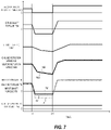
- FIG. 7 is an explanatory diagram illustrating an operation of the vehicle drive system when transitioned to an accelerator off state.
- FIG. 1 schematically illustrates an overall configuration of a vehicle drive system P according to one embodiment of the present invention.
- the vehicle drive system P includes an engine 1 and a motor-generator 5 as driving sources.
- the engine 1 and the motor-generator 5 are both coupled to right and left driving wheels 8 .
- an automatic transmission TM is interposed on a power transmission path coupling the engine 1 to the driving wheels 8 .
- the motor-generator 5 is coupled to the driving wheels 8 via the automatic transmission TM (specifically, a variator 4 ). While in the embodiment, the engine 1 and the motor-generator 5 are coupled in parallel to the variator 4 via independent power transmission paths, the engine 1 and the motor-generator 5 may be disposed on an identical power transmission path that extends from the variator 4 .
- the automatic transmission TM is a continuously variable transmission, and includes a torque converter 2 , a clutch 3 , and the variator 4 in an order from a side close to the engine 1 on the power transmission path approaching the driving wheels 8 .
- the automatic transmission TM converts a rotative power input from the engine 1 and the motor-generator 5 at a predetermined speed ratio, and outputs to the driving wheels 8 via a differential gear 6 .
- the torque converter 2 includes a pump impeller 21 coupled to an input shaft of the torque converter 2 and a turbine runner 22 coupled to an output shaft of the torque converter 2 , and transmits the input rotative power to the output shaft via a fluid dynamic action.
- the torque converter 2 further includes a lock-up clutch 23 coupled to the output shaft, and directly couples the input shaft to the output shaft of the torque converter 2 by bringing the lock-up clutch 23 into an engaged state to ensure reducing a transmission loss due to a fluid connection.
- An engagement and a disengagement of the lock-up clutch 23 can be switched by controlling a hydraulic pressure affecting the lock-up clutch 23 .
- the clutch 3 is disposed between the torque converter 2 and the variator 4 , and includes a friction engaging element (hereinafter referred to as an “input element”) 31 coupled to a crankshaft (an output shaft of the torque converter 2 in this embodiment) of the engine 1 and a friction engaging element (hereinafter referred to as an “output element”) 32 coupled to the input shaft (specifically, a rotation shaft of a primary pulley 41 ) of the variator 4 .
- the clutch 3 engages and disengages the input element 31 and the output element 32 to couple and cuts off the engine 1 to/from the variator 4 and the driving wheels 8 .
- the operation of the clutch 3 is controlled by adjusting the hydraulic pressure affecting the input element 31 or the output element 32 .
- the variator 4 includes the primary pulley 41 and a secondary pulley 42 as variating elements, and includes a metal belt 43 wound between this pair of pulleys 41 and 42 .
- the variator 4 ensures steplessly changing a speed ratio by changing a ratio of a contact diameter of the metal belt 43 on the primary pulley 41 and the secondary pulley 42 .
- the speed ratio of the variator 4 is controlled by adjusting the hydraulic pressure affecting movable sheaves of the primary pulley 41 and the secondary pulley 42 , and changing widths of V-grooves formed between the movable sheaves and fixed sheaves.
- the motor-generator 5 can function as an electric generator not only functioning as an electric motor. It is possible to employ an electric motor operable only as the electric motor, instead of the motor-generator 5 .
- the motor-generator 5 includes a rotor 51 coupled to the output shaft and a stator 52 disposed in a concentric manner with the rotor 51 in the peripheral area of the rotor 51 . By controlling a supply of the electric power to an electromagnetic coil disposed in the stator 52 , the motor-generator 5 can function as the electric motor to generate a torque.
- the torque of the motor-generator 5 is transmitted to a rotation shaft of the variator 4 (an input shaft and the rotation shaft of the primary pulley 41 in this embodiment) via a power transmission medium, such as a gear.
- the supply of the electric power to the motor-generator 5 is controlled by a power control unit in which an inverter 55 is incorporated.
- a direct current supplied from a battery 9 is converted into a three-phase alternating current by the inverter 55 , and is supplied to the motor-generator 5 .
- the alternating current generated by a regeneration operation of the motor-generator 5 is converted into a direct current by the inverter 55 , and is supplied to the battery 9 .
- the battery 9 is rechargeable by the current supplied from the motor-generator 5 .
- a rotative power after shifting that is output from the automatic transmission TM is transmitted to a drive shaft 7 via a gear train set to a predetermined gear ratio and the differential gear 6 to rotate the driving wheels 8 .
- the motor-generator 5 is coupled to the drive shaft 7 without via the clutch 3 .
- the motor-generator 5 may be coupled to the drive shaft 7 by interposing a clutch in a disengageable/engageable manner between the motor-generator 5 and the drive shaft 7 .
- the embodiment includes the lock-up clutch 23 of the torque converter 2 , the input element 31 and the output element 32 of the clutch 3 , and a mechanical drive type oil pump 10 as a source of generation of the hydraulic pressure affecting the variating elements 41 and 42 of the variator 4 .
- the oil pump 10 is driven by a rotative power of the engine 1 , increases the hydraulic oil pressure, and supplies the hydraulic oil to each portion via a hydraulic pressure control circuit 11 .
- FIG. 1 illustrates hydraulic pressure supply passages from the hydraulic pressure control circuit 11 to each portion by dotted lines with arrow heads.
- the embodiment includes an electrically operated type oil pump 12 in addition to the oil pump 10 .
- the oil pump 12 is actuated by an electric power supplied from the battery 9 , and increases the hydraulic oil pressure.
- the hydraulic oil after being increased can be supplied to each portion via the hydraulic pressure control circuit 11 similarly to the case by the oil pump 10 .
- the electrically operated type oil pump 12 can, for example, control the hydraulic pressure applied to the clutch 3 during a stop of the engine 1 .
- the controller 101 is configured as an electronic control unit, and is formed of a central processing unit (CPU), various kinds of storage devices, such as a RAM and a ROM, and a microcomputer including, for example, input/output interfaces.
- CPU central processing unit
- storage devices such as a RAM and a ROM
- microcomputer including, for example, input/output interfaces.
- the controller 101 is one that provides a function of a “control unit” according to the embodiment, and a “control device for a vehicle” according to the embodiment is configured by including the drive shaft 7 , the engine 1 , and the motor-generator 5 besides the controller 101 .
- the rotation shaft (hereinafter, referred to as an “output shaft” in some cases) 7 coupled to the driving wheels 8 is supposed to be a “drive shaft,” the “drive shaft” is not limited to the output shaft 7 , and may be any shaft that can transmit the rotative power from the engine 1 and the motor-generator 5 to the driving wheels 8 , such as a rotation shaft of the primary pulley 41 or a rotation shaft of the secondary pulley 42 .
- the “control device for a vehicle” can be configured by including the rotation shaft of the primary pulley 41 or the like instead of the output shaft 7 .
- a signal from an accelerator sensor 111 that detects an operation amount (hereinafter, referred to as an “accelerator pedal opening”) APO of the accelerator pedal by a driver, and a signal from a vehicle speed sensor 112 that detects a vehicle traveling speed (hereinafter, referred to as a “vehicle speed”) VSP are input to the controller 101 in relation to a driving force control of the vehicle, as well as signals from various kinds of sensors that detect, for example, a rotation speed NE of the engine 1 , a temperature TW of a cooling water of the engine 1 , a rotation speed Npri of the primary pulley 41 , a rotation speed Nsec of the secondary pulley 42 , a pressure Ppri of the hydraulic oil affecting the primary pulley 41 , a pressure Psec of the hydraulic oil affecting the secondary pulley 42 , a temperature Toil of the hydraulic oil of the automatic transmission TM, and a position SFT of a shift lever, are input.
- the controller 101 determines a region to which a current operating state of the vehicle belongs on the basis of the various kinds of signals, such as the accelerator pedal opening APO and the vehicle speed VSP, and switches the driving sources between the engine 1 and the motor-generator 5 corresponding to its determination result.
- the motor-generator 5 serves as the driving source in an operating range (hereinafter, referred to as a “first region”) R 1 on a low load side with the accelerator pedal opening APO being less than a predetermined degree of opening APO 1
- the engine 1 serves as the driving source in an operating range (hereinafter, referred to as a “second region”) R 2 on a high load side with the accelerator pedal opening APO being equal to or more than the predetermined degree of opening APO 1 .
- the driving source is alternatively selected between the engine 1 and the motor-generator 5 .
- the motor-generator 5 serves as the driving source in the first region R 1
- the engine 1 and the motor-generator 5 may be used in combination as the driving source in the second region R 2 to execute a torque assist by the motor-generator 5 .
- FIG. 4 illustrates an exemplary operating range map.
- the operating range map is defined by the accelerator pedal opening APO and the vehicle speed VSP, and, on the basis of the degree of opening APO 1 preliminarily determined corresponding to the vehicle speed VSP, the region less than the predetermined degree of opening APO 1 (illustrated with diagonal lines) corresponds to the first region R 1 and the region equal to or more than the predetermined degree of opening APO 1 corresponds to the second region R 2 .
- the predetermined degree of opening APO 1 is set to a different value depending on the vehicle speed VSP, specifically, set to a small value as the vehicle speed VSP is in a high region, it is also possible to set the predetermined degree of opening APO 1 to a constant value.
- the controller 101 compares the current accelerator pedal opening APO with the predetermined degree of opening APO 1 on the basis of the vehicle speed VSP to determine the regions R 1 and R 2 to which the operating states belong.
- the engine 1 When the accelerator pedal opening APO is less than the predetermined degree of opening APO 1 , and the motor-generator 5 is selected as the driving source, the engine 1 is stopped and the clutch 3 is disengaged.
- the traveling in such a state is referred to as an “EV traveling.”
- the accelerator pedal opening APO is equal to or more than the predetermined degree of opening APO 1 , and the engine 1 is selected as the driving source, the supply of the electric power to the motor-generator 5 is stopped and the clutch 3 is engaged to ensure the transmission of the rotative power to the drive shaft 7 from the engine 1 .
- the traveling in such a state is referred to as an “engine traveling.”
- the controller 101 executes a control to, while gradually decreasing the torque of the engine 1 , gradually increase the torque of the motor-generator 5 corresponding to the decrease of the engine torque. This suppresses the generation of the shock in association with the switching of the driving sources.
- FIG. 4 indicates an exemplary case of the switching caused by the driver returning the accelerator pedal by arrows a 1 and a 2 , and an exemplary case of the switching caused by the increase of the travelling resistance by an arrow a 3 .
- the driving source is returned to the engine 1 in order to switch from the EV traveling to the engine traveling again, and a fuel injection quantity to the engine 1 is increased in order to ensure outputting the engine torque corresponding to the accelerator pedal opening APO after the increase.
- a fuel injection quantity to the engine 1 is increased in order to ensure outputting the engine torque corresponding to the accelerator pedal opening APO after the increase.
- there exists a delay in the torque of the engine 1 until it actually starts to be increased since a torque increase instruction to the engine 1 in other words, since an increase instruction of the fuel injection quantity. Therefore, only simply outputting the torque increase instruction to the engine 1 in response to the increase of the accelerator pedal opening APO causes a shortage in the torque transmitted to the drive shaft 7 (hereinafter, referred to as a “drive shaft torque”).
- a control to increase the torque of the motor-generator 5 is executed in conjunction with the torque increase instruction to the engine 1 . This compensates the delay in the engine torque with the torque of the motor-generator 5 to secure a driving response of the vehicle.
- the control executed by the controller 101 regarding the switching of the driving sources will be described with reference to the following flowchart.
- FIG. 2 illustrates a basic procedure of the driving source switching control with a flowchart.
- the signals indicative of the operating state of the vehicle such as the accelerator pedal opening APO and the vehicle speed VSP, are read.
- the condition is satisfied for the transition from the engine traveling to the EV traveling or not. Specifically, it is determined whether the operating state has transitioned from the second region R 2 where the accelerator pedal opening APO is equal to or more than the predetermined degree of opening APO 1 to the first region R 1 where the accelerator pedal opening APO is less than the predetermined degree of opening APO 1 or not.
- the process proceeds to S 103 , and when it is not in such a condition, the process returns to S 101 to repeatedly execute the process at S 101 and 102 .
- the switching of the driving sources is started.
- the control to increase the torque of the motor-generator 5 while decreasing the torque of the engine 1 is executed, and, for example, while gradually decreasing the torque of the engine 1 , the torque of the motor-generator 5 is increased corresponding to the decrease of the engine torque.
- the decrease of the engine torque is, for example, caused by changing the fuel injection quantity of the engine 1 at a decrease rate that ensures the suppressed shock in association with the switching.
- the torque of the motor-generator 5 is increased so as to compensate for the shortage amount of the engine torque with respect to the drive shaft torque corresponding to the accelerator pedal opening APO.
- S 104 it is determined whether the switching of the driving sources from the engine 1 to the motor-generator 5 is completed or not. For example, it is determined whether the fuel injection quantity of the engine 1 is decreased down to a preliminarily set fuel cut injection quantity or zero or not. When the fuel injection quantity is sufficiently decreased, and the switching of the driving sources is completed, the process proceeds to S 105 , and when it is not yet completed, in other words, when the fuel injection quantity is not decreased down to the fuel cut injection quantity or zero, and it is during the switching of the driving sources, the process proceeds to S 107 .
- the clutch 3 is disengaged to cut off the transmission of the rotative power to the drive shaft 7 from the engine 1 . That is, in the embodiment, after the accelerator pedal opening APO is decreased to less than the predetermined degree of opening APO 1 , and the operating state is transitioned to the first region R 1 , the clutch 3 is not disengaged, and the engaged state is maintained until the switching of the driving sources to the motor-generator 5 is completed.
- the accelerator pedal opening APO is increased to equal to or more than the predetermined degree of opening APO 1 or not, in other words, after the operating state is transitioned from the second region R 2 on the high load side to the first region R 1 on the low load side, whether the operating state is transitioned to the second region R 2 again or not.
- the process proceeds to S 201 illustrated in FIG. 3 , and when the accelerator pedal opening APO is not increased to equal to or more than the predetermined degree of opening APO 1 , that is, when the accelerator pedal opening APO still remains in less than the predetermined degree of opening APO 1 , the process proceeds to S 108 .
- the torque increase instruction is output to the engine 1 in order to switch the driving sources to the engine 1 again. Specifically, a target value of the engine torque that ensures achieving the drive shaft torque corresponding to the accelerator pedal opening APO after the increase is set, and the fuel injection quantity of the engine 1 is increased on the basis of this target engine torque.
- the torque of the motor-generator 5 is controlled to increase the torque of the motor-generator 5 so as to compensate for the shortage amount of the actual engine torque with respect to the target drive shaft torque.
- this increases an inclination of the torque change generated by the motor-generator 5 more than that before the transition of the operating range, in other words, before the accelerator pedal opening APO is increased to equal to or more than the predetermined degree of opening APO 1 .
- the actual engine torque may be detected by installing a sensor at an appropriate rotating shaft, such as the input shaft of the torque converter 2 , it is also possible to detect by an estimation calculation based on the current engine torque and the target engine torque by approximating the delay of the actual engine torque with respect to the target engine torque as a primary delay.
- decreasing the torque of the motor-generator 5 so as to be in coordination with the increase of the engine torque achieves the drive shaft torque corresponding to the accelerator pedal opening APO, in other words, the drive shaft torque desired by the driver.
- matching of the torque of the engine 1 and the drive shaft torque completes the switching of the driving sources to the engine 1 . This completes the transition to the engine traveling, and the vehicle travels using the engine 1 as the driving source.
- the accelerator pedal opening APO is increased to equal to or more than the predetermined degree of opening APO 1 during the switching of the driving sources, and when the driving source is returned to the engine 1 , the clutch 3 is maintained in the engaged state through the whole control from the start of the driving source switching control (S 103 ) to the completion of the return to the engine 1 (S 205 ).
- control unit In the embodiment, the functions of the “control unit” are achieved by the processes at S 102 to 104 , S 107 , and S 108 in the flowchart illustrated in FIG. 2 , and the processes at S 201 to 204 in the flowchart illustrated in FIG. 3 .
- FIG. 5 schematically illustrates an operation of a vehicle drive system P by the driving source switching control according to the embodiment by a timing chart
- FIG. 6 illustrates the operation by the comparative example.
- a rotational speed NE and a torque TE of the engine 1 are indicated by dotted lines
- a rotational speed NM and a torque TM of the motor-generator 5 are indicated by solid lines
- a torque (input shaft torque) TSi applied to the input shaft of the variator 4 is indicated by a two-dot chain line.
- the control to switch the driving sources from the engine 1 to the motor-generator 5 is executed in order to transition from the engine traveling to the EV traveling when the accelerator pedal is returned from a state where the operating state is in a medium load region (APO APO 1 ) to be transitioned to the low load region (the first region R 1 ) where the accelerator pedal opening APO is less than the predetermined degree of opening APO 1 (time t 1 ).
- the controller 101 outputs an instruction to decrease the fuel injection quantity to the engine 1 .
- the controller 101 increases the torque of the motor-generator 5 corresponding to the decrease of the engine torque (time t 2 ) to suppress the generation of the shock in association with the switching of the driving sources.
- the supply of the fuel to the engine 1 is stopped to complete the switching of the driving sources to the motor-generator 5 and the transition to the EV traveling.
- the accelerator pedal opening APO is increased to be equal to or more than the predetermined degree of opening APO 1 again (time t 3 )
- the operation by the control according to the embodiment will be described.
- the operation from time t 1 where the accelerator pedal is returned to transition the operating state to the first region R 1 on the low load side to time t 3 where the accelerator pedal is pressed by, for example, a change-of-mind of the driver during the switching of the driving sources to increase the accelerator pedal opening APO to equal to or more than the predetermined degree of opening APO 1 again is similar to that of the comparative example.
- a torque TM of the motor-generator 5 is increased more than that when the accelerator pedal opening APO is increased (time t 3 ), and afterwards, the torque TM of the motor-generator 5 is decreased when the change of an actual engine torque TE is shifted to the increase (time t 4 ).
- the torque corresponding to the actual shortage amount of the engine torque with respect to the target value of the drive shaft torque TSd is generated by the motor-generator 5 .
- FIG. 5 illustrates a state where the inclination in the change of the torque TM of the motor-generator 5 is increased more than that before the increase of the accelerator pedal opening APO in response to the increase of the accelerator pedal opening APO, and furthermore, the change of the torque TM of the motor-generator 5 is also shifted to the decrease from the increase at time t 4 where the change of the actual engine torque TE is shifted to the increase from the decrease.
- APO state of accelerator off
- the switching of the driving sources is not performed, and the engine 1 continuously serves as the driving source.
- maintaining the clutch 3 in the engaged state and operating the motor-generator 5 as the electric generator increase the load applied to the drive shaft 7 from the engine 1 and the motor-generator 5 .
- the accelerator pedal is pressed and the accelerator pedal opening APO is increased (time t 31 )
- the regeneration operation of the motor-generator 5 is stopped and the supply of the fuel to the engine 1 is resumed.
- control device for the vehicle according to the embodiment is configured as described above.
- the following describes the effects obtained by the embodiment.
- the vehicle includes a drive shaft, an engine coupled to the drive shaft, and an electric motor coupled to the drive shaft.
- the control device for the vehicle includes a control unit that, when an accelerator pedal opening is increased to be equal to or more than a predetermined degree of opening during switching of driving sources which decreases a torque of the engine gradually and increases a torque of the electric motor corresponding to a decrease of the engine torque, gives an instruction to increase a torque to the engine, and increases a changing rate of a torque of the electric motor more than the changing rate of the torque of the electric motor before the accelerator pedal opening is increased to equal to or more than the predetermined degree of opening.
- the control device for the vehicle in which, after the accelerator pedal opening is increased to equal to or more than the predetermined degree of opening, the control unit sets a target torque of the engine corresponding to the accelerator pedal opening after the increase, and decreases the torque of the electric motor while increasing the torque of the engine toward the target torque.
- control device for the vehicle in which the predetermined degree of opening has a different value depending on a vehicle speed.
- control unit has a second region where the accelerator pedal opening is equal to or more than the predetermined degree of opening as an operating range where a traveling is performed by the engine, and a first region where the accelerator pedal opening is less than the predetermined degree of opening (excluding accelerator off state) as an operating range where a traveling is performed by the electric motor.
- the control unit executes the switching of the driving sources when the operating state is transitioned from the second region to the first region.
- control unit increases a load applied to the drive shaft from the engine and the electric motor when an accelerator-on state is changed to an accelerator-off state.
Landscapes
- Engineering & Computer Science (AREA)
- Chemical & Material Sciences (AREA)
- Combustion & Propulsion (AREA)
- Transportation (AREA)
- Mechanical Engineering (AREA)
- Automation & Control Theory (AREA)
- Power Engineering (AREA)
- Hybrid Electric Vehicles (AREA)
- Electric Propulsion And Braking For Vehicles (AREA)
Abstract
Description
Claims (5)
Applications Claiming Priority (4)
| Application Number | Priority Date | Filing Date | Title |
|---|---|---|---|
| JP2017165381 | 2017-08-30 | ||
| JPJP2017-165381 | 2017-08-30 | ||
| JP2017-165381 | 2017-08-30 | ||
| PCT/JP2018/032182 WO2019044997A1 (en) | 2017-08-30 | 2018-08-30 | Vehicle control device and vehicle control method |
Publications (2)
| Publication Number | Publication Date |
|---|---|
| US20210039625A1 US20210039625A1 (en) | 2021-02-11 |
| US11407398B2 true US11407398B2 (en) | 2022-08-09 |
Family
ID=65525722
Family Applications (1)
| Application Number | Title | Priority Date | Filing Date |
|---|---|---|---|
| US16/640,821 Active 2039-05-19 US11407398B2 (en) | 2017-08-30 | 2018-08-30 | Control device for vehicle and control method for vehicle |
Country Status (5)
| Country | Link |
|---|---|
| US (1) | US11407398B2 (en) |
| JP (1) | JP6860678B2 (en) |
| CN (1) | CN111032466B (en) |
| DE (1) | DE112018004909T5 (en) |
| WO (1) | WO2019044997A1 (en) |
Families Citing this family (2)
| Publication number | Priority date | Publication date | Assignee | Title |
|---|---|---|---|---|
| CN111051168B (en) * | 2017-08-30 | 2023-03-24 | 加特可株式会社 | Vehicle control device and vehicle control method |
| DE102020204561A1 (en) | 2020-04-08 | 2021-10-14 | Volkswagen Aktiengesellschaft | Method for controlling a drive train of a hybrid vehicle |
Citations (6)
| Publication number | Priority date | Publication date | Assignee | Title |
|---|---|---|---|---|
| JP2005051947A (en) * | 2003-07-30 | 2005-02-24 | Honda Motor Co Ltd | Hybrid vehicle |
| JP3624575B2 (en) * | 1996-09-24 | 2005-03-02 | トヨタ自動車株式会社 | Drive control apparatus for hybrid vehicle |
| JP2008273460A (en) | 2007-05-02 | 2008-11-13 | Nissan Motor Co Ltd | Drive control apparatus for hybrid vehicle |
| WO2015008394A1 (en) * | 2013-07-17 | 2015-01-22 | トヨタ自動車株式会社 | Control device for hybrid vehicle |
| US9623867B2 (en) * | 2013-04-26 | 2017-04-18 | Nissan Motor Co., Ltd. | Clutch control device for hybrid vehicle |
| US9840247B2 (en) * | 2014-12-19 | 2017-12-12 | Toyota Jidosha Kabushiki Kaisha | Hybrid vehicle |
Family Cites Families (6)
| Publication number | Priority date | Publication date | Assignee | Title |
|---|---|---|---|---|
| JP5680279B2 (en) * | 2008-03-06 | 2015-03-04 | 日産自動車株式会社 | Engine stop control device for hybrid vehicle |
| JP5228542B2 (en) * | 2008-03-07 | 2013-07-03 | 日産自動車株式会社 | Hybrid vehicle mode switching control device |
| JP2009214564A (en) * | 2008-03-07 | 2009-09-24 | Nissan Motor Co Ltd | Mode switching control device for hybrid vehicle |
| JP5492048B2 (en) * | 2010-10-25 | 2014-05-14 | 日産自動車株式会社 | Vehicle travel control device |
| JP6115022B2 (en) * | 2012-04-19 | 2017-04-19 | 日産自動車株式会社 | Vehicle control device |
| JP6654074B2 (en) | 2016-03-18 | 2020-02-26 | ベバスト ジャパン株式会社 | Vehicle retractable roof |
-
2018
- 2018-08-30 WO PCT/JP2018/032182 patent/WO2019044997A1/en not_active Ceased
- 2018-08-30 CN CN201880056200.5A patent/CN111032466B/en active Active
- 2018-08-30 DE DE112018004909.4T patent/DE112018004909T5/en active Pending
- 2018-08-30 JP JP2019539628A patent/JP6860678B2/en active Active
- 2018-08-30 US US16/640,821 patent/US11407398B2/en active Active
Patent Citations (6)
| Publication number | Priority date | Publication date | Assignee | Title |
|---|---|---|---|---|
| JP3624575B2 (en) * | 1996-09-24 | 2005-03-02 | トヨタ自動車株式会社 | Drive control apparatus for hybrid vehicle |
| JP2005051947A (en) * | 2003-07-30 | 2005-02-24 | Honda Motor Co Ltd | Hybrid vehicle |
| JP2008273460A (en) | 2007-05-02 | 2008-11-13 | Nissan Motor Co Ltd | Drive control apparatus for hybrid vehicle |
| US9623867B2 (en) * | 2013-04-26 | 2017-04-18 | Nissan Motor Co., Ltd. | Clutch control device for hybrid vehicle |
| WO2015008394A1 (en) * | 2013-07-17 | 2015-01-22 | トヨタ自動車株式会社 | Control device for hybrid vehicle |
| US9840247B2 (en) * | 2014-12-19 | 2017-12-12 | Toyota Jidosha Kabushiki Kaisha | Hybrid vehicle |
Also Published As
| Publication number | Publication date |
|---|---|
| US20210039625A1 (en) | 2021-02-11 |
| CN111032466B (en) | 2022-10-28 |
| DE112018004909T5 (en) | 2020-06-18 |
| CN111032466A (en) | 2020-04-17 |
| JPWO2019044997A1 (en) | 2020-11-19 |
| WO2019044997A1 (en) | 2019-03-07 |
| JP6860678B2 (en) | 2021-04-21 |
Similar Documents
| Publication | Publication Date | Title |
|---|---|---|
| KR101719948B1 (en) | Malfunction determination device and malfunction determination method for hybrid vehicle | |
| US7498757B2 (en) | Control device for a hybrid electric vehicle | |
| US10507833B2 (en) | Vehicle control device and method for controlling the same | |
| CN105190110B (en) | Control device of belt type continuously variable transmission | |
| CN107429827B (en) | Hydraulic control device and hydraulic control method for vehicle | |
| RU2527652C2 (en) | Hybrid carrier accelerator pedal depressing force control device | |
| US9234579B2 (en) | Control device and control method for vehicular electric oil pump | |
| EP2199646A2 (en) | Control apparatus for belt-type continuously-variable transmission | |
| US10253876B2 (en) | Vehicle regenerative speed control device | |
| JP6115022B2 (en) | Vehicle control device | |
| US20040063539A1 (en) | Hydraulic control apparatus for vehicle and method thereof | |
| US11407398B2 (en) | Control device for vehicle and control method for vehicle | |
| KR101665279B1 (en) | Failure determination device for hybrid vehicles and failure determination method therefor | |
| US11235753B2 (en) | Control device for vehicle and control method for vehicle | |
| US10240672B2 (en) | Control device for continuously variable transmission and method for controlling the same | |
| US11383697B2 (en) | Vehicle control apparatus | |
| JP5880775B2 (en) | Shift control device for automatic transmission | |
| US11407403B2 (en) | Vehicle control apparatus | |
| US11524670B2 (en) | Control device for vehicle and control method for vehicle | |
| JP2018154146A (en) | Vehicle control apparatus and vehicle control method | |
| JP2006220114A (en) | Engine controller, vehicle controller, and its control method | |
| JP2018154145A (en) | Vehicle control apparatus and vehicle control method | |
| JP2017047790A (en) | VEHICLE CONTROL DEVICE AND ITS CONTROL METHOD | |
| JP2006336796A (en) | Control device for belt type continuously variable transmission |
Legal Events
| Date | Code | Title | Description |
|---|---|---|---|
| AS | Assignment |
Owner name: JATCO LTD, JAPAN Free format text: ASSIGNMENT OF ASSIGNORS INTEREST;ASSIGNORS:NISHIHIRO, YOSHIMASA;MOCHIZUKI, MASAHARU;ENOMOTO, TAKASHI;SIGNING DATES FROM 20200203 TO 20200212;REEL/FRAME:051885/0437 Owner name: NISSAN MOTOR CO., LTD., JAPAN Free format text: ASSIGNMENT OF ASSIGNORS INTEREST;ASSIGNORS:NISHIHIRO, YOSHIMASA;MOCHIZUKI, MASAHARU;ENOMOTO, TAKASHI;SIGNING DATES FROM 20200203 TO 20200212;REEL/FRAME:051885/0437 |
|
| FEPP | Fee payment procedure |
Free format text: ENTITY STATUS SET TO UNDISCOUNTED (ORIGINAL EVENT CODE: BIG.); ENTITY STATUS OF PATENT OWNER: LARGE ENTITY |
|
| STPP | Information on status: patent application and granting procedure in general |
Free format text: APPLICATION DISPATCHED FROM PREEXAM, NOT YET DOCKETED |
|
| STPP | Information on status: patent application and granting procedure in general |
Free format text: DOCKETED NEW CASE - READY FOR EXAMINATION |
|
| STPP | Information on status: patent application and granting procedure in general |
Free format text: NOTICE OF ALLOWANCE MAILED -- APPLICATION RECEIVED IN OFFICE OF PUBLICATIONS |
|
| STCF | Information on status: patent grant |
Free format text: PATENTED CASE |
|
| MAFP | Maintenance fee payment |
Free format text: PAYMENT OF MAINTENANCE FEE, 4TH YEAR, LARGE ENTITY (ORIGINAL EVENT CODE: M1551); ENTITY STATUS OF PATENT OWNER: LARGE ENTITY Year of fee payment: 4 |