US11397203B2 - Estimating method for braking resistor - Google Patents
Estimating method for braking resistor Download PDFInfo
- Publication number
- US11397203B2 US11397203B2 US16/851,732 US202016851732A US11397203B2 US 11397203 B2 US11397203 B2 US 11397203B2 US 202016851732 A US202016851732 A US 202016851732A US 11397203 B2 US11397203 B2 US 11397203B2
- Authority
- US
- United States
- Prior art keywords
- electrical machine
- switch
- state
- control system
- machine control
- Prior art date
- Legal status (The legal status is an assumption and is not a legal conclusion. Google has not performed a legal analysis and makes no representation as to the accuracy of the status listed.)
- Active, expires
Links
Images


Classifications
-
- G—PHYSICS
- G01—MEASURING; TESTING
- G01R—MEASURING ELECTRIC VARIABLES; MEASURING MAGNETIC VARIABLES
- G01R27/00—Arrangements for measuring resistance, reactance, impedance, or electric characteristics derived therefrom
- G01R27/02—Measuring real or complex resistance, reactance, impedance, or other two-pole characteristics derived therefrom, e.g. time constant
- G01R27/08—Measuring resistance by measuring both voltage and current
-
- H—ELECTRICITY
- H02—GENERATION; CONVERSION OR DISTRIBUTION OF ELECTRIC POWER
- H02P—CONTROL OR REGULATION OF ELECTRIC MOTORS, ELECTRIC GENERATORS OR DYNAMO-ELECTRIC CONVERTERS; CONTROLLING TRANSFORMERS, REACTORS OR CHOKE COILS
- H02P27/00—Arrangements or methods for the control of AC motors characterised by the kind of supply voltage
- H02P27/04—Arrangements or methods for the control of AC motors characterised by the kind of supply voltage using variable-frequency supply voltage, e.g. inverter or converter supply voltage
- H02P27/06—Arrangements or methods for the control of AC motors characterised by the kind of supply voltage using variable-frequency supply voltage, e.g. inverter or converter supply voltage using dc to ac converters or inverters
-
- H—ELECTRICITY
- H02—GENERATION; CONVERSION OR DISTRIBUTION OF ELECTRIC POWER
- H02P—CONTROL OR REGULATION OF ELECTRIC MOTORS, ELECTRIC GENERATORS OR DYNAMO-ELECTRIC CONVERTERS; CONTROLLING TRANSFORMERS, REACTORS OR CHOKE COILS
- H02P3/00—Arrangements for stopping or slowing electric motors, generators, or dynamo-electric converters
- H02P3/06—Arrangements for stopping or slowing electric motors, generators, or dynamo-electric converters for stopping or slowing an individual dynamo-electric motor or dynamo-electric converter
- H02P3/18—Arrangements for stopping or slowing electric motors, generators, or dynamo-electric converters for stopping or slowing an individual dynamo-electric motor or dynamo-electric converter for stopping or slowing an ac motor
- H02P3/22—Arrangements for stopping or slowing electric motors, generators, or dynamo-electric converters for stopping or slowing an individual dynamo-electric motor or dynamo-electric converter for stopping or slowing an ac motor by short-circuit or resistive braking
-
- H—ELECTRICITY
- H02—GENERATION; CONVERSION OR DISTRIBUTION OF ELECTRIC POWER
- H02P—CONTROL OR REGULATION OF ELECTRIC MOTORS, ELECTRIC GENERATORS OR DYNAMO-ELECTRIC CONVERTERS; CONTROLLING TRANSFORMERS, REACTORS OR CHOKE COILS
- H02P6/00—Arrangements for controlling synchronous motors or other dynamo-electric motors using electronic commutation dependent on the rotor position; Electronic commutators therefor
- H02P6/24—Arrangements for stopping
-
- H—ELECTRICITY
- H02—GENERATION; CONVERSION OR DISTRIBUTION OF ELECTRIC POWER
- H02P—CONTROL OR REGULATION OF ELECTRIC MOTORS, ELECTRIC GENERATORS OR DYNAMO-ELECTRIC CONVERTERS; CONTROLLING TRANSFORMERS, REACTORS OR CHOKE COILS
- H02P23/00—Arrangements or methods for the control of AC motors characterised by a control method other than vector control
- H02P23/14—Estimation or adaptation of motor parameters, e.g. rotor time constant, flux, speed, current or voltage
Definitions
- the present disclosure relates to an estimating method, and more particularly to an estimating method of estimating a resistance value of a braking resistor, which is applicable to an electrical machine control system.
- an electrical machine control system is used for controlling an electrical machine and providing electric power to the electrical machine.
- the electrical machine When the electrical machine is operated in a generator mode, the mechanical energy is converted into electric energy and the electric energy is recharged to the DC link voltage of the electrical machine control system.
- a power conversion circuit or a rectifying circuit of the electrical machine control system is only able to perform a unidirectional power conversion, the electric energy that is recharged to the electrical machine control system cannot be merged into the utility power system.
- it is usually equipped with a braking resistor. By the braking resistor, the electric energy that is recharged to the electrical machine control system is therefore consumed in the form of heat. Since the DC link voltage is prevented from rising gradually, the purpose of protecting the electrical machine control system can be achieved.
- a discharging loop of the electrical machine control system further comprises a power switch. If the resistance value of the braking resistor is improper, the braking current is too large. Consequently, the lifespan of the power switch is reduced, or even the power switch will be burnt out. In a more serious situation, the electrical machine control system cannot be operated normally.
- An object of the present disclosure provides an estimating method for a braking resistor.
- the resistance value of the braking resistor is estimated according to the operating parameters of the electrical machine control system. Consequently, the user can determine whether the resistance value of the braking resistor is proper. Since the possibility of erroneously using the braking resistor is reduced, the problem of burning out the power switch is avoided.
- an estimating method for an electrical machine control system is provided.
- the electrical machine control system is configured to control operations of an electrical machine and brake the electrical machine when entering a generator mode.
- the electrical machine control system includes a bus capacitor, a braking resistor and a switch.
- the braking resistor is electrically connected between the bus capacitor and the switch.
- the estimating method includes the following steps. Firstly, a step (S1) is performed to determine whether the electrical machine control system is in the generator mode. In a step (S2), if a determination of the step (S1) is satisfied, a bus voltage across both terminals of the bus capacitor is monitored continuously. Then, a step (S3) is performed to determine whether the switch is turned to an on state.
- a step (S4) if a determination of the step (S3) is satisfied, a first current value of a current flowing through the bus capacitor during an off state of the switch is calculated according to a voltage variation of the bus capacitor from the off state of the switch to the on state of the switch, a time duration of the switch in the off state and a known capacitance value of the bus capacitor.
- a step (S5) the switch is turned to the on state. Then, a step (S6) is performed to determine whether the switch is turned to the off state.
- a second current value of a current flowing through the bus capacitor during the on state of the switch is calculated according to a voltage variation of the bus capacitor from the on state of the switch to the off state of the switch, a time duration of the switch in the on state and the known capacitance value of the bus capacitor, and a resistance value of the braking resistor is estimated according to the first current value and the second current value.
- FIGS. 1A and 1B illustrate a flowchart of an estimating method for a braking resistor according to an embodiment of the present disclosure
- FIG. 2 is a schematic circuit diagram illustrates an electrical machine control system using the estimating method of the present disclosure
- FIG. 3 is a working quadrant diagram illustrating the operations of the electrical machine control system as shown in FIG. 2 ;
- FIG. 4 is a schematic timing waveform diagram illustrating associated signals of the electrical machine control system as shown in FIG. 2 in the generator mode;
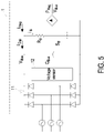
- FIG. 5 is a schematic circuit diagram illustrates the electrical machine control system as shown in FIG. 2 when the electrical machine control system is in the generator mode and the switch is in the on state;
- FIG. 6 is a schematic circuit diagram illustrates the electrical machine control system as shown in FIG. 2 when the electrical machine control system is in the generator mode and the switch is in the off state.
- FIGS. 1A, 1B and 2 illustrate a flowchart of an estimating method for a braking resistor according to an embodiment of the present disclosure.
- FIG. 2 is a schematic circuit diagram illustrates an electrical machine control system using the estimating method of the present disclosure.
- the estimating method can be applied to an electrical machine control system 1 .
- the electrical machine control system 1 is an electrical machine control system of an elevator.
- the electrical machine control system 1 is electrically connected with an electrical machine 2 (e.g., a motor) in order to provide electric power to the electrical machine 2 and control the operations of the electrical machine 2 .
- an electrical machine 2 e.g., a motor
- a power conversion circuit or a rectifier circuit of the electrical machine control system 1 is able to perform a unidirectional power conversion.
- the electrical machine control system 1 can be operated in a motor (drive) mode or a generator (brake) mode.
- the received input AC energy is converted by the electrical machine control system 1 , and the converted electric energy is provided to the electrical machine 2 to drive the operations of the electrical machine 2 .
- the electrical machine control system 1 brakes the electrical machine 2 . Under this circumstance, the mechanical energy is converted into electric energy by the electrical machine 2 , and the converted electric energy is recharged to the electrical machine control system 1 or an energy storage device (not shown).
- FIG. 3 is a working quadrant diagram illustrating the operations of the electrical machine control system 1 as shown in FIG. 2 .
- the operations of the electrical machine control system 1 may be divided into four conditions.
- the electrical machine control system 1 is used to the control of the motor of an elevator.
- the elevator may be moved upstairs or downstairs.
- the motor may be rotated in two opposite directions accordingly (i.e., a forward rotation and a reverse rotation).
- the output torque of the elevator also has positive and negative values corresponding to the requirements of the elevator's acceleration and deceleration motions. According to the forward rotation or the reverse rotation of the motor and the positive value or the negative value of the output torque, the operating conditions of the electrical machine control system 1 may be expressed by four working quadrants.
- the electrical machine control system 1 drives the forward rotation of the electrical machine 2 . Meanwhile, the rotating speed of the electrical machine 2 is positive (>0), the torque of the electrical machine 2 is positive (>0), and the output power P of the electrical machine 2 is positive (>0).
- the arrow directions as shown in FIG. 2 indicate the electric energy conversion directions of the electrical machine control system 1 corresponding to the positive value and the negative value of the output power P.
- the electrical machine 2 is rotated forwardly, and the electrical machine control system 1 brakes the electrical machine 2 . Meanwhile, the rotating speed of the electrical machine 2 is positive (>0), the torque of the electrical machine 2 is negative ( ⁇ 0), and the output power P of the electrical machine 2 is negative ( ⁇ 0).
- the electrical machine control system 1 drives the reverse rotation of the electrical machine 2 . Meanwhile, the rotating speed of the electrical machine 2 is negative ( ⁇ 0), the torque of the electrical machine 2 is negative ( ⁇ 0), and the output power P of the electrical machine 2 is positive (>0).
- the electrical machine 2 is rotated reversely, and the electrical machine control system 1 brakes the electrical machine 2 . Meanwhile, the rotating speed of the electrical machine 2 is negative ( ⁇ 0), the torque of the electrical machine 2 is positive (>0), and the output power P of the electrical machine 2 is negative ( ⁇ 0).
- the operating condition of the electrical machine control system 1 is in the first quadrant or the third quadrant of FIG. 3 .
- the electrical machine control system 1 is in the generator mode, the operating condition of the electrical machine control system 1 is in the second quadrant or the fourth quadrant of FIG. 3 .
- the estimating method is executed when the electrical machine control system 1 is in the generator mode. That is, the operating condition of the electrical machine control system 1 is in the second quadrant or the fourth quadrant of FIG. 3 .
- the electrical machine control system 1 comprises a frequency converter power module 10 , a rectifier circuit 11 , a bus capacitor C Bus , a braking resistor R B , a (power) switch S B and a voltage sensor 12 .
- the rectifier circuit 11 is electrically connected with an input terminal of the electrical machine control system 1 . After the input AC energy is received by the electrical machine control system 1 , the input AC energy is converted into DC energy by the rectifier circuit 11 .
- the bus capacitor C Bus is electrically connected with an output terminal of the rectifier circuit 11 . By the bus capacitor C Bus , the DC energy from the rectifier circuit 11 is stabilized.
- the voltage sensor 12 is electrically connected with both terminals of the bus capacitor C Bus .
- a bus voltage V Bus of the bus capacitor C Bus is sensed by the voltage sensor 12 .
- the braking resistor R B is electrically connected between the bus capacitor C Bus and the switch S B . While the electric energy of the electrical machine 2 is recharged to the electrical machine control system 1 in the generator mode, the recharged electric energy is consumed by the braking resistor R B .
- the braking resistor R B and the switch S B are electrically connected with each other in series.
- the serially-connected structure of the braking resistor R B and the switch S B is further connected with the bus capacitor C Bus in parallel.
- An input terminal of the frequency converter power module 10 is electrically connected with the bus capacitor C Bus .
- An output terminal of the frequency converter power module 10 is electrically connected with the electrical machine 2 .
- the stabilized DC energy from the bus capacitor C Bus is converted into an output AC energy by the frequency converter power module 10 .
- the electrical machine 2 is powered by the output AC energy.
- the switch S B is in an open status (i.e., an off state).
- the switch S B is turned to the open status (i.e., the off state) or a close status (i.e., an on state).
- FIG. 4 is a schematic timing waveform diagram illustrating associated signals of the electrical machine control system as shown in FIG. 2 in the generator mode.
- FIG. 5 is a schematic circuit diagram illustrates the electrical machine control system as shown in FIG. 2 when the electrical machine control system is in the generator mode and the switch is in the on state.
- FIG. 6 is a schematic circuit diagram illustrates the electrical machine control system as shown in FIG. 2 when the electrical machine control system is in the generator mode and the switch is in the off state.
- the estimating method comprises the following steps. Firstly, a step S1 is performed to determine whether the electrical machine control system 1 is in a generator mode. If the determination of the step S1 is satisfied, a step S2 is performed.
- step S2 the bus voltage V Bus of the bus capacitor C Bus is monitored by the voltage sensor 12 continuously. Since the bus voltage V Bus of the bus capacitor C Bus is monitored by the voltage sensor 12 continuously, the bus voltage V Bus of the bus capacitor C Bus can be used in the following steps S3 and S6 to confirm whether the switch S B is in the on state or the off state.
- a step S3 is performed to determine whether the switch S B is turned to the on state. If the determination of the step S3 is satisfied, a step S4 is performed.
- the current flowing through the bus capacitor C Bus during the off state of the switch S B is calculated according to a voltage variation of the bus capacitor C Bus from the off state of the switch S B to the on state of the switch S B , a time duration of the switch S B in the off state and a known capacitance value of the bus capacitor C Bus .
- the time duration of the switch S B in the off state indicates the time interval from the off state of the switch S B to the on state of the switch S B after the electrical machine control system 1 enters the generator mode.
- the current flowing through the bus capacitor C Bus may be expressed by the following mathematic formula (1):
- i Cap is the current flowing through the bus capacitor C Bus
- C is the known capacitance value of the bus capacitor C Bus
- V Bus is the bus voltage of the bus capacitor C Bus .
- the voltage variation of the bus capacitor C Bus from the off state of the switch S B to the on state of the switch S B is the difference between the voltage V 1 (at time t 1 ) and the voltage V 2 (at time t 2 ), and time duration of the switch S B in the off state is the time interval between the time t 1 and the time t 2 .
- the value of the current flowing through the bus capacitor C Bus during the off state of the switch S B may be referred as a first current value.
- the recharge current i Reg of the electrical machine 2 recharged to the electrical machine control system 1 is equal to the current i Cap which flowing through the bus capacitor C Bus (i.e., the first current value). Consequently, the recharge current i Reg may be expressed by the following mathematic formula (2):
- i Reg is also equal to the recharge power P Reg of the electrical machine 2 recharged to the electrical machine control system 1 divided by the bus voltage V Bus of the bus capacitor C Bus .
- step S5 is performed.
- the switch S B is turned to the on state. For example, at the time t 2 , the switch S B is turned to the on state.
- a step S6 is performed to determine whether the switch S B is turned to the off state.
- a step S7 is performed.
- the current flowing through the bus capacitor C Bus during the on state of the switch S B is calculated according to a voltage variation of the bus capacitor C Bus from the on state of the switch S B to the off state of the switch S B , a time duration of the switch S B in the on state and the known capacitance value of the bus capacitor C Bus .
- the value of the current flowing through the bus capacitor C Bus during the on state of the switch S B may be referred as a second current value.
- the time duration of the switch S B in the on state indicates the time interval from the on state of the switch S B to the off state of the switch S B after the electrical machine control system 1 enters the generator mode.
- a third current value of a current flowing through the braking resistor R B is estimated according to a difference between the first current value and the second current value. After the voltage variation of the bus capacitor C Bus from the on state of the switch S B to the off state of the switch S B is divided by the third current value, a resistance value of the braking resistor R B is estimated.
- the current flowing through the bus capacitor C Bus during the on state of the switch S B is calculated according to the voltage variation of the bus capacitor C Bus from the on state of the switch S B to the off state of the switch S B , the time duration of the switch S B in the on state and the known capacitance value of the bus capacitor C Bus .
- the voltage variation of the bus capacitor C Bus from the on state of the switch S B to the off state of the switch S B is the difference between the voltage V 2 (at time t 2 ) and the voltage V 3 (at time t 3 ), and time duration of the switch S B in the on state is the time interval between the time t 2 and the time t 3 .
- the value of the current flowing through the bus capacitor C Bus during the on state of the switch S B may be referred as a second current value. Consequently, the second current value may be expressed by the following mathematic formula (3):
- the recharge current i Reg of the electrical machine 2 recharged to the electrical machine control system 1 when the switch S B is in the on state and the recharge current i Reg of the electrical machine 2 recharged to the electrical machine control system 1 when the switch S B is in the off state are substantially equal.
- the recharge current i Reg of the mathematic formula (4) may be introduced into the mathematic formula (2).
- the current i Cap flowing through the bus capacitor C Bus (i.e., the second current value) has been obtained in the mathematic formula (3).
- the current is flowing through the braking resistor R B (i.e., the third current value) can be estimated.
- the switch S B is in the on state
- the current is flowing through the braking resistor R B (i.e., the third current value) is known, and the bus voltage V Bus of the bus capacitor C Bus is sensed by the voltage sensor 12 continuously. Consequently, the resistance value Rr of the braking resistor R B can be estimated according to the following mathematic formula (5):
- step S1 is repeatedly performed. If the determination of the step S3 is not satisfied, the step S3 is repeatedly performed. If the determination of the step S6 is not satisfied, the step S6 is repeatedly performed. After the step S7 is completed, the switch S B is turned to the off state. If desired, the step S1 could be started again to estimate the resistance value Rr of the braking resistor R B .
- step S3 if the bus voltage V Bus of the bus capacitor C Bus is increased to reach or above a first threshold voltage value, the electrical machine control system 1 determines that the switch S B is turned to the on state.
- step S6 if the bus voltage V Bus of the bus capacitor C Bus is decreased to reach or below a second threshold voltage value, the electrical machine control system 1 determines that the switch S B is turned to the off state.
- step S6 if the time duration of the switch S B in the on state reaches a threshold time interval, the electrical machine control system 1 determines that the switch S B is turned to the off state.
- the present disclosure provides an estimating method for a braking resistor. While the electrical machine control system is in a generator mode, the resistance value of the braking resistor is estimated according to the operating parameters of the electrical machine control system. Consequently, the user can determine whether the resistance value of the braking resistor is proper. If the braking resistor is improper, another proper braking resistor is employed or an associated protection mechanism is enabled. Consequently, the lifespan of the power switch in the discharging loop of the electrical machine control system is prolonged, and the problem of burning out the power switch is avoided.
Abstract
Description
i B =i Reg −i Cap (4)
Claims (10)
Applications Claiming Priority (2)
| Application Number | Priority Date | Filing Date | Title |
|---|---|---|---|
| CN201910906123.4A CN112630538B (en) | 2019-09-24 | 2019-09-24 | Method for estimating braking resistance |
| CN201910906123.4 | 2019-09-24 |
Publications (2)
| Publication Number | Publication Date |
|---|---|
| US20210088566A1 US20210088566A1 (en) | 2021-03-25 |
| US11397203B2 true US11397203B2 (en) | 2022-07-26 |
Family
ID=74880776
Family Applications (1)
| Application Number | Title | Priority Date | Filing Date |
|---|---|---|---|
| US16/851,732 Active 2041-02-13 US11397203B2 (en) | 2019-09-24 | 2020-04-17 | Estimating method for braking resistor |
Country Status (2)
| Country | Link |
|---|---|
| US (1) | US11397203B2 (en) |
| CN (1) | CN112630538B (en) |
Citations (16)
| Publication number | Priority date | Publication date | Assignee | Title |
|---|---|---|---|---|
| US5513058A (en) | 1994-03-03 | 1996-04-30 | General Electric Company | DC link circuit for an electronically commutated motor |
| US7996167B2 (en) | 2008-08-14 | 2011-08-09 | Lg Chem, Ltd. | Apparatus and method for estimating resistance characteristics of battery based on open circuit voltage estimated by battery voltage variation pattern |
| US20120119685A1 (en) * | 2008-03-10 | 2012-05-17 | Hitachi Industrial Equipment Systems Co., Ltd | Power transducer |
| WO2013186065A1 (en) | 2012-06-13 | 2013-12-19 | Schneider Toshiba Inverter Europe Sas | Method for estimating the value of a braking resistor used in a power converter |
| CN103792430A (en) | 2012-10-26 | 2014-05-14 | 无锡华润上华科技有限公司 | Self-adaptive range resistance test method |
| TW201513553A (en) | 2013-05-16 | 2015-04-01 | Mitsubishi Electric Corp | Motor control apparatus |
| TW201615988A (en) | 2014-10-23 | 2016-05-01 | 台達電子工業股份有限公司 | Control method of screw pump and control system using the same |
| TW201621337A (en) | 2014-12-05 | 2016-06-16 | 財團法人工業技術研究院 | Method and system for online estimating internal resistance of battery |
| WO2016101074A1 (en) | 2014-12-23 | 2016-06-30 | General Magnetic International Inc. | Brake system and controller for use with a wellhead direct drive |
| CN106006250A (en) * | 2015-03-24 | 2016-10-12 | 上海三菱电梯有限公司 | Control method for elevator energy-saving device |
| JP6015690B2 (en) * | 2014-02-27 | 2016-10-26 | 三菱電機株式会社 | Elevator control device |
| CN106443241A (en) | 2016-08-31 | 2017-02-22 | 株洲中车时代电气股份有限公司 | Monitoring method and device and protection method and device of train braking resistor |
| WO2017194196A1 (en) | 2016-05-13 | 2017-11-16 | Sew-Eurodrive Gmbh & Co. Kg | Converter system comprising an ac/dc converter and method for operating a converter system |
| CN107797056A (en) | 2017-10-31 | 2018-03-13 | 苏州汇川联合动力系统有限公司 | Braking resistor loop contactor adhesion detecting system and method |
| CN208937644U (en) | 2018-08-29 | 2019-06-04 | 长沙市小为电子科技有限公司 | Braking resistor qualitative detection circuit and its frequency converter |
| WO2019138554A1 (en) | 2018-01-12 | 2019-07-18 | 株式会社日立産機システム | Voltage imbalance assessment method and power conversion device |
-
2019
- 2019-09-24 CN CN201910906123.4A patent/CN112630538B/en active Active
-
2020
- 2020-04-17 US US16/851,732 patent/US11397203B2/en active Active
Patent Citations (16)
| Publication number | Priority date | Publication date | Assignee | Title |
|---|---|---|---|---|
| US5513058A (en) | 1994-03-03 | 1996-04-30 | General Electric Company | DC link circuit for an electronically commutated motor |
| US20120119685A1 (en) * | 2008-03-10 | 2012-05-17 | Hitachi Industrial Equipment Systems Co., Ltd | Power transducer |
| US7996167B2 (en) | 2008-08-14 | 2011-08-09 | Lg Chem, Ltd. | Apparatus and method for estimating resistance characteristics of battery based on open circuit voltage estimated by battery voltage variation pattern |
| WO2013186065A1 (en) | 2012-06-13 | 2013-12-19 | Schneider Toshiba Inverter Europe Sas | Method for estimating the value of a braking resistor used in a power converter |
| CN103792430A (en) | 2012-10-26 | 2014-05-14 | 无锡华润上华科技有限公司 | Self-adaptive range resistance test method |
| TW201513553A (en) | 2013-05-16 | 2015-04-01 | Mitsubishi Electric Corp | Motor control apparatus |
| JP6015690B2 (en) * | 2014-02-27 | 2016-10-26 | 三菱電機株式会社 | Elevator control device |
| TW201615988A (en) | 2014-10-23 | 2016-05-01 | 台達電子工業股份有限公司 | Control method of screw pump and control system using the same |
| TW201621337A (en) | 2014-12-05 | 2016-06-16 | 財團法人工業技術研究院 | Method and system for online estimating internal resistance of battery |
| WO2016101074A1 (en) | 2014-12-23 | 2016-06-30 | General Magnetic International Inc. | Brake system and controller for use with a wellhead direct drive |
| CN106006250A (en) * | 2015-03-24 | 2016-10-12 | 上海三菱电梯有限公司 | Control method for elevator energy-saving device |
| WO2017194196A1 (en) | 2016-05-13 | 2017-11-16 | Sew-Eurodrive Gmbh & Co. Kg | Converter system comprising an ac/dc converter and method for operating a converter system |
| CN106443241A (en) | 2016-08-31 | 2017-02-22 | 株洲中车时代电气股份有限公司 | Monitoring method and device and protection method and device of train braking resistor |
| CN107797056A (en) | 2017-10-31 | 2018-03-13 | 苏州汇川联合动力系统有限公司 | Braking resistor loop contactor adhesion detecting system and method |
| WO2019138554A1 (en) | 2018-01-12 | 2019-07-18 | 株式会社日立産機システム | Voltage imbalance assessment method and power conversion device |
| CN208937644U (en) | 2018-08-29 | 2019-06-04 | 长沙市小为电子科技有限公司 | Braking resistor qualitative detection circuit and its frequency converter |
Also Published As
| Publication number | Publication date |
|---|---|
| US20210088566A1 (en) | 2021-03-25 |
| CN112630538A (en) | 2021-04-09 |
| CN112630538B (en) | 2024-04-16 |
Similar Documents
| Publication | Publication Date | Title |
|---|---|---|
| EP2944502B1 (en) | Electric motor vehicle | |
| EP2853353B1 (en) | Electric power tool | |
| US6457565B2 (en) | Elevator apparatus with rechargeable power supply and discharge control | |
| US11458844B2 (en) | Power supply system for vehicle | |
| JP5725544B2 (en) | Power converter and power control method | |
| JP7140045B2 (en) | drive circuit | |
| US20140022681A1 (en) | Power supply system, vehicle incorporating the same and method for controlling power supply system | |
| US20180358837A1 (en) | Charging control device | |
| US10381846B2 (en) | Electric vehicle | |
| CN109687696B (en) | Power supply system | |
| JP4391513B2 (en) | Control device for vehicle alternator | |
| KR20120113165A (en) | Method for controlling charging current | |
| JP2007209056A (en) | Capacitor device | |
| CN109039221B (en) | Active short circuit and motor controller | |
| US20140152108A1 (en) | Discharge control system and discharge device | |
| JP6015690B2 (en) | Elevator control device | |
| US11397203B2 (en) | Estimating method for braking resistor | |
| CN112511071B (en) | Control device of power conversion device | |
| CN110771023B (en) | Synchronous rectification type DC-DC converter and switching power supply device | |
| JP2778485B2 (en) | Uninterruptible power system | |
| JP2001253653A (en) | Elevator system | |
| TWI724557B (en) | Estamating method for braking resistor | |
| EP2361819A2 (en) | Relay welding detecting device | |
| US11424696B2 (en) | Motor drive device | |
| JP2011166989A (en) | Drive device |
Legal Events
| Date | Code | Title | Description |
|---|---|---|---|
| AS | Assignment |
Owner name: DELTA ELECTRONICS, INC., TAIWAN Free format text: ASSIGNMENT OF ASSIGNORS INTEREST;ASSIGNORS:TSENG, SHAO-KAI;WU, SHENG-HAN;REEL/FRAME:052429/0105 Effective date: 20200415 |
|
| FEPP | Fee payment procedure |
Free format text: ENTITY STATUS SET TO UNDISCOUNTED (ORIGINAL EVENT CODE: BIG.); ENTITY STATUS OF PATENT OWNER: LARGE ENTITY |
|
| STPP | Information on status: patent application and granting procedure in general |
Free format text: DOCKETED NEW CASE - READY FOR EXAMINATION |
|
| STPP | Information on status: patent application and granting procedure in general |
Free format text: NOTICE OF ALLOWANCE MAILED -- APPLICATION RECEIVED IN OFFICE OF PUBLICATIONS |
|
| STPP | Information on status: patent application and granting procedure in general |
Free format text: PUBLICATIONS -- ISSUE FEE PAYMENT VERIFIED |
|
| STCF | Information on status: patent grant |
Free format text: PATENTED CASE |