US11378539B2 - Fabrication of iridium oxide pH sensors and sensory arrays - Google Patents
Fabrication of iridium oxide pH sensors and sensory arrays Download PDFInfo
- Publication number
- US11378539B2 US11378539B2 US15/023,627 US201415023627A US11378539B2 US 11378539 B2 US11378539 B2 US 11378539B2 US 201415023627 A US201415023627 A US 201415023627A US 11378539 B2 US11378539 B2 US 11378539B2
- Authority
- US
- United States
- Prior art keywords
- layer
- electrode
- micro
- dispensing
- sensors
- Prior art date
- Legal status (The legal status is an assumption and is not a legal conclusion. Google has not performed a legal analysis and makes no representation as to the accuracy of the status listed.)
- Active, expires
Links
Images


Classifications
-
- G—PHYSICS
- G01—MEASURING; TESTING
- G01N—INVESTIGATING OR ANALYSING MATERIALS BY DETERMINING THEIR CHEMICAL OR PHYSICAL PROPERTIES
- G01N27/00—Investigating or analysing materials by the use of electric, electrochemical, or magnetic means
- G01N27/26—Investigating or analysing materials by the use of electric, electrochemical, or magnetic means by investigating electrochemical variables; by using electrolysis or electrophoresis
- G01N27/28—Electrolytic cell components
- G01N27/30—Electrodes, e.g. test electrodes; Half-cells
- G01N27/302—Electrodes, e.g. test electrodes; Half-cells pH sensitive, e.g. quinhydron, antimony or hydrogen electrodes
-
- C—CHEMISTRY; METALLURGY
- C23—COATING METALLIC MATERIAL; COATING MATERIAL WITH METALLIC MATERIAL; CHEMICAL SURFACE TREATMENT; DIFFUSION TREATMENT OF METALLIC MATERIAL; COATING BY VACUUM EVAPORATION, BY SPUTTERING, BY ION IMPLANTATION OR BY CHEMICAL VAPOUR DEPOSITION, IN GENERAL; INHIBITING CORROSION OF METALLIC MATERIAL OR INCRUSTATION IN GENERAL
- C23F—NON-MECHANICAL REMOVAL OF METALLIC MATERIAL FROM SURFACE; INHIBITING CORROSION OF METALLIC MATERIAL OR INCRUSTATION IN GENERAL; MULTI-STEP PROCESSES FOR SURFACE TREATMENT OF METALLIC MATERIAL INVOLVING AT LEAST ONE PROCESS PROVIDED FOR IN CLASS C23 AND AT LEAST ONE PROCESS COVERED BY SUBCLASS C21D OR C22F OR CLASS C25
- C23F1/00—Etching metallic material by chemical means
-
- G—PHYSICS
- G01—MEASURING; TESTING
- G01N—INVESTIGATING OR ANALYSING MATERIALS BY DETERMINING THEIR CHEMICAL OR PHYSICAL PROPERTIES
- G01N27/00—Investigating or analysing materials by the use of electric, electrochemical, or magnetic means
- G01N27/26—Investigating or analysing materials by the use of electric, electrochemical, or magnetic means by investigating electrochemical variables; by using electrolysis or electrophoresis
- G01N27/27—Association of two or more measuring systems or cells, each measuring a different parameter, where the measurement results may be either used independently, the systems or cells being physically associated, or combined to produce a value for a further parameter
-
- G—PHYSICS
- G01—MEASURING; TESTING
- G01N—INVESTIGATING OR ANALYSING MATERIALS BY DETERMINING THEIR CHEMICAL OR PHYSICAL PROPERTIES
- G01N27/00—Investigating or analysing materials by the use of electric, electrochemical, or magnetic means
- G01N27/26—Investigating or analysing materials by the use of electric, electrochemical, or magnetic means by investigating electrochemical variables; by using electrolysis or electrophoresis
- G01N27/416—Systems
- G01N27/4166—Systems measuring a particular property of an electrolyte
- G01N27/4167—Systems measuring a particular property of an electrolyte pH
Definitions
- the present invention relates in general to the field of sensors, and more particularly to the fabrication of amorphous iridium oxide film pH sensors.
- ion-sensitive field-effect transistor (iSFET) pH sensors [1-5], optical fiber pH sensors [1, 6-11], hydrogel film pH sensors [12-14], and solid state pH sensors [1, 15-18] have been proposed.
- iSFET sensors have power consumption concerns due to the field-effect transistor (FET) operational requirements [19].
- Hydrogel film pH sensors utilize the physical properties of the pH-responsive swelling and shrinking polymer to measure resistance changes [12].
- the sensor structure design and polymer layer fabrication process can be complicated and expensive [13].
- Optical pH sensors also have power consumption issues due to the use of light sources.
- a system including optical devices could be expensive and unsuitable for implantation [1, 7-8, 10-11].
- Iridium oxide film IROF has exhibited outstanding stability over wide pH ranges, rapid response, less hysteresis, and high durability; these characteristics have been demonstrated at high temperature up to 250° C. [23].
- iridium oxide films There are different fabrication methods for iridium oxide films including sputtering deposition [23, 24], electrochemical deposition [25-29], thermal oxidation [23], and sol-gel [30-32] processes.
- the sputtering iridium oxide film (SIROF) deposition process is costly due to the target cost.
- the oxygen and argon pressure ratios, position of the target, deposition rate, and RF powers during the fabrication processes all affect the pH sensing parameters such as potential drifts and redox interference [22].
- Anodic electrochemical deposition presents an economical way for iridium oxide thin film fabrication.
- the anodic iridium oxide thin film (AIROF) process is based on electrolysis of a solution containing iridium complexes.
- the iridium tetrachloride compound has been widely used as a deposition agent [26-29] such as the commonly used Yamanaka solution [26].
- the pH value of the deposition solution, solution temperature and current density control affect the deposition efficiency [26-29].
- a precise power supply system as potentiostate is required in the electro-deposition process for thickness and film quality control.
- Thermal oxidation processes require a high temperature ranging from 500 to 800° C. [17, 22].
- the film made by thermal oxidation can be thicker than the AIROF with more stable potentials [22, 23].
- the film surface has a tendency to crack after the high temperature treatment. The adhesion property of the cracked film then becomes an issue.
- the high temperature treatment also becomes a limitation during sensor fabrication, especially for the use of polymer and photoresist, which often can not survive at a temperature above 200° C.
- the sol-gel IROF deposition process has been demonstrated [32] with dip coating [32, 33] and heat treatment [31, 32] procedures. Sol-gel deposition provides a simpler and economical fabrication approach.
- Integrating pH sensors in microfluidic systems can provide in-situ measurement functionality for micro-scale fluidic processing and analyzing applications, especially for medicine synthesis, bioanalysis of drugs and environmental specimens, and biological studies of cells.
- Conventional methods to monitor pH levels inside microfluidic channels using pH responsive dyes or tag-based indicators possess several disadvantages, including potential contamination, photo-bleaching of the indicators, and narrow dynamic responses.
- miniaturized electrochemical pH sensors for microfluidic systems have been proposed to overcome these issues while providing real-time and time-lapsed measurement results.
- the present invention provides a fabrication method for sol-gel based iridium oxide (IrOx) thin film pH sensors and microelectrodes.
- the invention further provides microelectrode arrays produced by the fabrication methods and microfluidic devices including the microelectrodes and microelectrode arrays.
- the invention is a method for fabricating a microelectrode pH sensor.
- a metal layer is deposited on a substrate.
- a first layer and a second layer are deposited on a substrate.
- the first layer is chromium and the second layer is gold.
- the chromium and gold layers are coated with a photoresist layer and an electrode is defined photolithographically.
- the gold and chromium layers are etched to define the electrode.
- a microfluidic mold is supplied which includes a reservoir region and a channel.
- the microfluidic mold is made by pouring and curing polydimethylsiloxane (PDMS) on a silicon wafer comprising a patterned SU-8 mold.
- PDMS polydimethylsiloxane
- the PDMS layer is peeled off of the silicon wafer to form the microfluidic mold.
- the mold is made to correspond to the configuration of the electrode, as explained below.
- the microfluidic mold is detached from the glass substrate, the pH sensor is cured and coated with a photoresist, and the sensing sites are opened.
- one or more metal layers are deposited on the substrate by forming a pattern on the encapsulation layer, depositing at least one metal layer on the pH sensing array, and then opening the sensing electrode sites.
- the invention is a method for fabricating a microelectrode sensor array following a similar method as above for the electrode sensor.
- At least one metal layer is deposited on a substrate.
- first and second layers are deposited on a substrate.
- the first layer is chromium and the second layer is gold.
- the chromium and gold layers are coated with a photoresist layer and pattern of microelectrodes is defined photolithographically.
- the gold and chromium layers are etched to define the pattern of microelectrode array.
- a microfluidic mold is supplied which includes one or more reservoir regions and an array of channels leading from the reservoir region(s).
- the microfluidic mold is made by pouring and curing polydimethylsiloxane (PDMS) on a silicon wafer comprising a patterned SU-8 mold.
- PDMS polydimethylsiloxane
- the PDMS layer is peeled off of the silicon wafer to form the microfluidic mold.
- the mold is made to correspond to the configuration of the electrode sensor array, as explained below.
- microfluidic mold is aligned onto the electrode array-substrate assembly created as above so that a pathway is defined from the reservoir region(s) through the channels to the electrodes.
- an iridium oxide sol-gel solution is poured into the reservoir(s) so that it flows through the channels and coats the electrode sensors.
- the PDMS layer is detached from the glass substrate, the pH sensor array is cured and coated with a photoresist and the sensing sites are opened.
- one or more metal layers are deposited on the substrate by forming a pattern on the encapsulation layer, depositing at least one metal layer on the pH sensing array, and then opening the sensing electrode sites.
- the substrate is a glass substrate.
- the chromium and gold may be deposited onto the glass substrate by any known method.
- the chromium and gold layers are deposited onto the glass substrate via e-beam evaporation.
- the photoresist may comprise any known photoresist composition and is preferably SU-8.
- the coating steps are accomplished via a spin-coating process. Typically, after the sol-gel solution is dispensed onto the array, excess sol-gel solution is retreated from the reservoir and the device is dried. After the PDMS is detached from the glass substrate, the sensor array is thermally treated.
- the invention further provides an apparatus comprising the microelectrode array produced according to the fabrication method described above integrated onto a microfluidic device.
- the advantages of the fabrication methods include that a small amount of sol-gel material can be deposited onto the metal electrode site.
- multiple sensors can be made by one deposition step of injecting the solution into the reservoir and the sensor electrodes performance will be uniform since the fabrication micro environment is identical for all sensors.
- FIG. 1 illustrates a pH sensor in accordance with one embodiment of the present invention.
- FIG. 2 illustrates an array of pH sensors in accordance with another embodiment of the present invention.
- FIGS. 3A-3H illustrate a method for fabricating a pH sensor in accordance with the methods of the present invention.
- Gold and Chromium are deposited on a glass slide ( FIG. 3A ); a NR-0 photoresist layer and pattern microelectrodes are spin-coated ( FIG. 3B ); the Au and Cr layers are etched ( FIG. 3C ); PDMS is poured on a silicon wafer with patterned SU-8 mold ( FIG. 3D ); the PDMS layer is peeled off the silicon wafer ( FIG. 3E ); the PDMS piece is aligned onto the microelectrodes ( FIG. 3F ); an IrOx sol-gel solution is dispensed and the IrOx cured ( FIG. 3G ); photoresist is spin-coated and pattern sensing sites for the micro pH sensors are opened ( FIG. 3H ).
- FIGS. 4A-4D illustrate a PDMS reservoir placed on top of a microelectrode array ( FIG. 4A ); a model of micro-channels to dispense sol-gel solution on the microelectrodes ( FIG. 4B ); a microscope image of IrOx on an electrode after coating ( FIG. 4C ); and an SEM photo of the surface of the IrOx microelectrode.
- FIGS. 5A-5C illustrate an experimental setup of a microfluidic device using a micro pH sensor array ( FIG. 5A ); the design of the microfluidic device ( FIG. 5B ); and pH spatial and temporal responses of the sensor array after adding 0.1M HCl solution to the reservoir.
- FIG. 6 shows a micrograph of the electrode array and illustrates the voltage response of two pH electrodes vs. an Ag/AgCl reference electrode.
- FIG. 7 illustrates the method of fabrication including additional steps 9 and 10 of depositing additional silver and chromium layers onto the glass substrate.
- FIG. 1 a pH sensor 100 in accordance with one embodiment of the present invention is shown.
- the pH sensor 100 includes a substrate 102 , an amorphous iridium oxide film sensor electrode 104 disposed on the substrate 102 and a reference electrode 106 disposed on the substrate 102 in close proximity to the amorphous iridium oxide film sensor electrode 104 .
- a first electrical contact pad 108 is disposed on the substrate 102 and is electrically connected to the amorphous iridium oxide sensor 104 via a conductive trace, connector, or pathway 112 .
- a second electrical contact pad 110 is disposed on the substrate 102 and electrically connected to the reference electrode via a conductive trace, connector, or pathway 114 .
- the amorphous iridium oxide film sensor electrode 104 provides a potential in reference to the reference electrode 106 that varies according to a pH of a substance contacting the amorphous iridium oxide film sensor electrode 104 and the reference electrode 106 .
- the present invention is not limited to the specific orientation shown in FIG. 1 .
- FIG. 1 is not to scale. As a result, any suitable orientation of the components can be used, and the components can be of any suitable geometric shape.
- One example of a process for fabricating the pH sensor 100 will be described in more detail below.
- the pH sensor array 200 includes four iridium oxide film pH sensors 100 a , 100 b , 100 c and 100 d disposed on a substrate 102 .
- the array can contain any number of pH sensors 100 .
- a reference electrode 106 is disposed on the substrate 102 in close proximity to each corresponding amorphous iridium oxide film sensor electrode 104 .
- a first electrical contact pad 108 corresponding to each amorphous iridium oxide film sensor electrode 104 is disposed on the substrate 102 and electrically connected to the corresponding amorphous iridium oxide sensor 104 via a conductive trace, connector, or pathway 112 .
- a second electrical contact pad 110 corresponding to each reference electrode 106 is disposed on the substrate 102 and electrically connected to the corresponding reference electrode 106 via a conductive trace, connector, or pathway 114 .
- the amorphous iridium oxide film sensor electrodes 104 provide a potential in reference to the reference electrodes 106 that varies according to a pH of a substance contacting the amorphous iridium oxide film sensor electrodes 104 and the reference electrodes 106 .
- the present invention is not limited to the specific orientation shown in FIG. 2 .
- FIG. 2 is not to scale. As a result, any suitable orientation of the components can be used, and the components can be of any suitable geometric shape.
- the fabrication processes are depicted in FIGS. 3A-3H and FIG. 7 .
- a metal layer here shown as layers of chromium 204 and gold 206 are deposited on a substrate 202 , preferably by e-beam evaporation ( FIG. 3A ).
- the substrate 202 is glass and optically transparent providing a compatible means for studies of cells.
- the substrate can be any appropriate material, such as a flexible polymer.
- the thickness of the chromium layer 204 is between 15 nm and 40 nm, preferably about 20 nm
- the thickness of the gold layer 206 is between 80 nm and 150 nm, preferably about 100 nm.
- Photolithography and etching processes are carried out to define the array configuration.
- a photoresist layer 208 and pattern microelectrodes are spin-coated onto the Cr/Au layers 204 / 206 .
- the Au and Cr layers 204 / 206 are then etched as illustrated in FIG. 3C and the photoresist layer 208 is removed as shown in FIG. 3F .
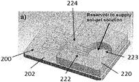
- the PDMS device 220 was aligned on top of the glass substrate 202 with each micro-dispensing channel 222 in contact with each metal electrode 224 , as shown in FIG. 3F and FIG. 4A .
- the IrOx sol-gel solution was prepared generally according to the method published in [1].
- One gram of anhydrous iridium chloride (IrCl4) was dissolved in 42 ml of ethanol. 10 ml of acetic acid was added in the solution.
- the coating solution was stirred by a magnetic rod for one hour.
- a small volume of this sol-gel solution 225 was dispensed into the PDMS reservoir 223 and allowed to automatically dispense across the coating sites 227 of each of the microelectrodes 224 as depicted in FIG. 3G .
- the set-up is illustrated in FIG. 4B .
- FIG. 4C shows iridium oxide film covered electrodes 224 after electrodeposition. EDAX analysis and SEM pictures, shown in FIG. 4D , confirmed the elements present on the electrode surface. Finally, a layer of SU-8 photoresist 226 was spin-coated and patterned to open only the sensing sites 228 as shown in FIG. 3H .
- step 7 dispensing and curing the IrOx 225 ; and removal of the microfluidic mold (step not shown), a coating of photoresist 226 is applied and then etched to form the desired pattern on the substrate 202 .
- One or more additional metal layers 230 , 232 are deposited to the device, to the substrate 202 , and then the photoresist layer 226 is removed.
- Microfluidic structures designed for specific studies were placed onto the glass substrate to incorporate the pH sensor array.
- the thickness of the IrOx layer deposited onto the electrodes was measured by a profilometer. A layer of IrOx at least 0.7 ⁇ m thick was deposited on the gold electrodes. The thickness can be controlled with the viscosity of solution and microfluidic channel designs.
- F is the Faraday's constant with a value of 96,487 coul/equiv.
- R is the gas constant with a value of 8.314 joules/deg.
- RT/F is equal to 25.688 at 25° C.
- the pH potential sensitivity is 59 mV/pH if space charges are formed [22, 46] which is called the Nernstian response.
- the pH sensitivity of our sensor is based on the super-Nernstian potential response [44] as the sensitivity will be higher than 59 mV/pH.
- the sensitivity of the IrOx pH sensor was validated by pH titration tests at room temperature. DI water, HCl, and KOH were used during the titrations. Three sensor electrodes in an array were used to demonstrate the linear super-Nernstian response. The results showed sensitivity ranging from ⁇ 71.5 mV/pH to ⁇ 81.7 mV/pH. Potential responses with seven different pH levels from 11.8 to 1.92 resulted in sensitivity between ⁇ 69.6 mV/pH and ⁇ 71.8 mV/pH as HCl was dripped in diluted KOH solution for titration. The different sensitivities may be caused by the state of oxide [49].
- the response time of the pH sensor was measured in three different tests. The first test was from the acid to alkaline condition by quickly dripping 0.1M KOH into an acidic solution contacting the sensor. The second test was from alkaline to acid by quickly dripping 0.1M HCl into an alkaline solution contacting the sensor. The third test involved dripping diluted HCl droplets directly on the dry sensing electrode surface of the sensor.
- the response time of pH electrodes is defined as the time needed for the potential change to reach 90% within the equilibrium value of potential [22].
- a response time of 0.9 second with a measured potential step change from pH 4 to 11 was obtained. From pH 12 to 3.5, the response time was about 2 seconds. With the dry electrode, adding pH 4 solution induced a potential step change with a response time of 0.8 s. The response times did vary due to the solution mixture, thus repeated experiments were conducted. Generally speaking the pH sensor responds to added solution within a time period of 2 s.
- FIG. 5A shows the experiment setup while FIG. 5B displays the dimension of the microfluidic device that had two reservoirs connected through a microfluidic flow tunnel with a height of 10 ⁇ m and a width of 100 ⁇ m. All five pH sensors shared the same standard Ag/AgCl reference as shown in FIG. 5A .
- the two reservoirs and the microfluidic flow tunnel were filled with phosphate buffered saline solution (pH 7.0).
- a chemical mixing incident was created by adding 0.1M HCl solution into the right reservoir.
- the micro pH sensors placed along the microfluidic flow tunnel monitored the change in pH of the solution corresponding to the diffusion of H + ions.
- FIG. 5A shows the experiment setup while FIG. 5B displays the dimension of the microfluidic device that had two reservoirs connected through a microfluidic flow tunnel with a height of 10 ⁇ m and a width of 100 ⁇ m.
- All five pH sensors shared the same standard Ag/AgCl reference as shown in FIG. 5A
- 5C displays the pH values indicated by different pH sensors located at different distances from the reservoir containing HCl.
- the pH values of the sensors decreased with time. After 1200 seconds, all sensors indicated pH values of around 1.5, which means the concentration of H + ions inside the microfluidic flow tunnel became homogeneous due to diffusion.
- the experiment thus demonstrated the use of the microelectrodes to spatially and temporally monitor pH change in microfluidic devices.
- the fabrication process described herein produces sol-gel-based micro pH sensors with a wide sensing range, robustness, and high durability for long-term experiments.
- Sol-gel coating solution was automatically distributed through micro-dispensing channels made of PDMS to the sensors with sensing sizes of 100 ⁇ 100 ⁇ m 2 .
- the fabrication approach described herein effectively enhances the reproducibility and mass production ability of the micro-scale pH sensors.
- the sensitivities of the sol-gel-based pH sensors produced using the methods of the present invention remained in the range of 51.0-56.1 mV/pH after three days of fabrication.
- the micro-electrode array was integrated to a microfluidic device to spatially and temporally monitor pH changes in a chemical mixing process.
- FIG. 6 shows a micrograph of a pH electrode array inside the transparent PDMS microfluidic structure. IrOx was coated on each electrode within an area of 100 ⁇ 100 ⁇ m 2 . The temporal response of the sensor array in a microfluidic flow tunnel with a 100- ⁇ m width connecting two chambers was tested. The chambers and tunnel were initially filled with DI water. Voltage responses of the 1st and the 5th electrodes were recorded versus a standard Ag/AgCl reference electrode when a droplet of buffer solution with pH 4 was added into one chamber which was closer to the 1st sensor. The buffer solution diffused through the microfluidic tunnel toward the other chamber.
- the 1st sensor reached a higher potential indicating a lower pH level than that of the 5th sensor due to the effect of dilution.
- the 1st sensor also responded more quickly than the 5th sensor indicating that the sensor detected the pH change first as the pH 4 buffer diffused through the tunnel.
- the sensitivities of sensors were tested within the range of 51.0-56.1 mV/pH.
- the present invention can be used to provide in-situ measurement functionality for micro-scale fluidic processing and analyzing applications, especially for medicine synthesis, bioanalysis of drugs and environmental specimens and biological studies of cells.
Abstract
Description
where: E0 is the standard electrode potential with a value of 926 mV;
- [1] John G. Webster, “The measurement, instrumentation and sensors handbook,” CRC Press and IEEE Press, pp. 71, Florida, 1999.
- [2] Young-Jin Kim, Young-Chul Lee, Byung-Ki sohn, Jung-Hee Lee, and Chang-Soo Kim, “A novel pH microsensor with a built-in reference electrode”, Journal of the Korean Physical Society, Vol. 43, pp. 769-772, 2003.
- [3] Yi Liu, Tianhoung Cui, “Ion-sensitive field-effect transistor based pH sensors using nano self-assembled polyelectrolyte/nanoparticle multilayer films,” Sensors and Actuators B, Vol. 123, pp. 148-152, August, 2006.
- [4] Jinghong Han, Dafu Cui, Yating Li, Hong Zhang, Yuzi Huang, Zipan Zheng, Yarning Zhu and Xiangming Li, “A gastroesophageal tract pH sensor based on the H-ISFET and the monitoring system for 24 h,” Sensors and Actuators B, Vol. 66, pp. 203-204, July, 2000.
- [5] Kalman Pasztor, A. Sekiguchi, N. Shimo, N. Kitamura and H. Masuhara, “Iridium oxide-based microelectrochemical transistors for pH sensing,” Sensors and Actuators B, Vol. 12, pp. 225-230, 1993.
- [6] Otto S. Wolfbeis, “Fiber-optic chemical sensors and biosensors,” Anal. Chem., Vol. 76, pp. 3269-3284, 2004.
- [7] Sheila A. Grant, Robert S. Glass, “A sol-gel based fiber optic sensor for local blood pH measurements,” Sensors and Actuators B, Vol. 45, pp. 35-42, 1997.
- [8] Saying Dong, Ming Luo, Gangding Peng, and Wenhua Cheng, “Broad range pH sensor based on sol-gel entrapped indicators on fiber optic,” Sensor and Actuators B: Chem. Vol. 129, pp. 94-98, January, 2008.
- [9] Zhe Jin, Yongxuan Su, and Yixiang Duan, “An improved optical pH sensor based on polyaniline,” Sensors and Actuators B, Vol. 71, pp. 118-122, November, 2000.
- [10] Afsaneh Safavi, Mozhgan, “Novel optical pH sensor for high and low pH values,” Sensors and Actuators B, Vol. 90, pp. 143-150, April, 2003.
- [11] E. Alvarado-Mendez, R. Rojas-Laguna, J. A. Andrade-Lucio, D. Hernandez-Cruz, R. A. Lessard, and J. G. Avina-Cervantes, “Design and characterization of pH sensor based on sol-gel silica layer on plastic optical fiber,” Sensors and Actuators B, Vol. 106, pp. 518-522, May, 2005.
- [12] Norman F. Sheppard, Jr., Matthew J. Lesho, Philip McNally, and A. Shaun Francomacaro, “Microfabricated conductimetric pH sensor,” Sensors and Actuators B, Vol. 28, pp. 95-102, August, 1995.
- [13] Gerald Gerlach, Margarita Guenther, Joerg Sorber, Gunnar Suchaneck, Karl-Friedrich Arndt, and Andreas Richter, “Chemical and pH sensors based on the swelling behavior of hydrogels,” Sensors and Actuators B, Vol. 111-112, pp. 555-561, November, 2005.
- [14] R. Bashir, J. Z. Hilt, O. Elibol, A. Gupta and N. A. Peppas, “Micromechanical cantilever as an ultrasensitive pH microsensor,” Applied Physics Letters, Vol. 81, pp. 3091-3093, 2002.
- [15] Agner Fog, Richard P. Buck, “Electronic semiconducting oxides as pH sensors,” Sensors and Actuators, Vol. 6, pp. 137-146, 1984.
- [16] T. Mikolajick, R. Kuhnhold, and H. Ryssel, “The pH-sensing properties of tantalum pentoxide films fabricated by metal organic low pressure chemical vapor deposition,” Sensors and Actuators B, Vol. 44, pp. 262-267, 1997.
- [17] Patrick J Kinlen, John E. Heider, and David E. Hubbard, “A solid-state pH sensor based on a Nafion-coated iridium oxide indicator electrode and a polymer-based silver chloride reference electrode,” Sensors and Actuators B, Vol. 22, pp. 13-25, October, 1994.
- [18] H. Neil McMurray, Peter Douglas, and Cuncan Abbot, “Novel thick-film pH sensors based on ruthenium dioxide-glass composites,” Sensors and Actuators B, Vol. 28, pp. 9-15, July, 1995.
- [19] Wouter Olthuis, “Chemical and physical FET based sensors or variations on an equation,” Sensor and Actuator B, Vol. 105, pp. 96-103, 2005.
- [20] Yi-Hung Liao and Jung-Chuan Chou, “Preparation and characteristics of ruthenium dioxide for pH array sensors with real-time measurement system,” Sensor and Actuators B: Chem., Vol. 128, pp. 603-612, January, 2007.
- [21] Chu-Neng Tsai, Jung-Chuan Chou, Tai-Ping Sun, and Shen-Kan Hsiung, “Study on the sensing characteristics and hysteresis effect of the tin oxide pH electrode,” Sensors and Actuators B, Vol. 18, pp. 877-882, July, 2005.
- [22] Sheng Yao, Min Wang, and Marc Madou, “A pH electrode based on melt-oxidized iridium oxide,” Journal of the Electrochemical Society, Vol. 148, pp. 29-36, 2001.
- [23] J. V. Dobson, P. R. Snodin and H. R. Thirsk, “EMF measurements of cells employing metal-metal oxide electrodes in aqueous chloride and sulphate electrolytes at temperatures between 25-250° C.,” Electrochimica Acta, Vol. 21, pp. 527-533, 1976.
- [24] T. Katsube, I. Lauks and J. N. Zemel, “pH-sensitive sputtered iridium oxide films,” Sensors and Actuators, Vol. 2, pp. 399-410, 1981.
- [25] M. F. Yuen, I. Lauks, and W. C. Dautremont-Smith, “pH dependent voltanmmetry of iridium oxide films,” Solid State Ionics, Vol. 11, pp. 19-29, 1983.
- [26] Kazusuke Yamanaka, “Anodically electrodeposited iridium oxide films (AEIROF) from alkaline solutions for electrochromic display devices,” Japanese Journal of Applied Physics, Vol. 28, pp. 632-637, 1989.
- [27] Michel A. Petit, Vincent Plichon, “Anodic electrodeposition of iridium oxide films,” Journal of Electroanalytical Chemistry, Vol. 444, pp. 247-252, 1998.
- [28] Sayed A. M. Marzouk, Stefan Ufer, Richard P. Buck, Timothy A. Johnson, Larry A. Dunlap, and Wayne E. Cascio, “Electrodeposited iridium oxide pH electrode for measurement of extracellular myocardial acidosis during acute ischemia,” Anal. Chem, Vol. 70, pp. 5054-5061, 1998.
- [29] Igor A. Ges, Borislav L. Ivanov, David K. Schaffer, Eduardo A. Lima, Andreas A. Werdich, and Franz J. Baudenbacher, “Thin-film IrOx pH microelectrode for microfluidic-based Microsystems,” Biosensors and Bioelectronics, Vol. 21, pp. 248-256, 2005.
- [30] K. Nishio, Y. Watanabe, T. Tsuchiya, “Preparation and properties of electrochromic iridium oxide thin film by sol-gel process,” Thin Solid Films, Vol. 350, pp. 96-100, 1999.
- [31] Akiyoshi Osaka, Toru Takatsuna and Yoshinari Miura, “Iridium oxide films via sol-gel processing,” Non-Crystalline Solids, pp. 313-319, 1994.
- [32] Keishi Nishio and Toshio Tsuchiya, “Electrochromic thin films prepared by sol-gel process,” Solar Energy Materials& Solar Cells, Vol. 68, pp. 279-293, 2001.
- [33] C. Jefferey Brinker, George W. Scherer, Sol-Gel Science: The physics and Chemistry of Sol-Gel Processing, pp. 788-798, Academic Press, Boston, 1990.
- [34] Sheila A. Grant, Kerry Bettencourt, Peter Krulevitch, Julie Hamilton and Robert Glass “In vitro and in vivo measurements of fiber optic and electrochemical sensors to monitor brain tissue pH,” Sensors and Actuators, Vol 72, pp. 174-179, January, 2001.
- [35] Sayed A. M. Marzouk, Stefan Ufer, Richard P. Buck, Timothy A. Johnson, Larry A. Dunlap, and Wayne E. Cascio, “Electrodeposited iridium oxide pH electrode for measurement of extracellular myocardial acidosis during acute ischemia,” Anal. Chem, Vol. 70, pp. 5054-5061, 1998.
- [36] Danny O'Hare, Kin H. Parker, and C. Peter Winlove, “Metal-metal oxide pH sensors for physiological application,” Medical Engineering and Physics, Vol. 28, pp 982-988, 2006.
- [37] Haley R. Clark, Timothy A. Barbari, “Modeling the response time of an in vivo glucose affinity sensor,” Biotechnol. Prog., Vol. 15, pp. 259-266, 1999.
- [38] L. L. Visch, P. Bergveld, W. Lamprecht, and E. J.'s-Gravenmade, “pH measurement with an ion sensitive field effect transistor in the mouth of patients with xerostomia,” IEEE Transactions on biomedical engineering, Vol. 38, pp. 353-356, 1991.
- [39] Robert J. Gillies, Natrarajan Raghunand, Maria L. Garcia-Martin, and Robert A. Gatenby, “pH imaging—A review of pH measurement methods and applications in cancers,” IEEE Engineering in medicine and biology magazine, pp. 58-64, 2004.
- [40] Alan H. Auerbach, Babs R. Soller, Robert A. Peura, and Russell F. Stahl, “Hypothermia effects microsensor measurement of tissue pH,” IEEE, pp. 830-831, 1994.
- [41] Erika Kress-Rogers, “Solid-state pH sensors for food application,” Elsevier Trends Journals, Vol. 2, pp. 320-324, 1990.
- [42] Cl. Bohnke, H. Duroy, and J.-L. Fourquet, “pH sensors with lithium lanthanum titanate sensitive material: applications in food industry,” Sensors and Actuators B, Vol. 89, pp. 240-247, 2003.
- [43] Matthew F. Smiechowski, Vadim F. Lvovich, “Iridium oxide sensors for acidity and basicity detection in industrial lubricants,” Sensors and Actuators B, Vol. 96, pp. 261-267, November, 2003.
- [44] Erno Pungor, “The theory of ino-selective electrodes,” The Japan Society for Analytical Chemistry, Vol. 14, pp. 249-256, 1998.
- [45] A. W. J. Cranny, J. K. Atkinson, “Thick film silver-silver chloride reference electrodes,” Meas. Sci Technol, pp. 1557-1565, 1998.
- [46] M. Pourbaix, “Atlas of electrochemical equilibria in aqueous solutions,” National Association of Corrosion Engineers, pp. 374-377, 1974.
- [47] S. Ardizzone, A. Carugati, S. Trasatti, “Properties of thermally prepared iridium dioxide electrodes,” J. Electroanal. Cheml., Vol. 126, pp. 287-292, 1981.
- [48] J. Hendrikese, W. Olthuis, P. Bergveld, “A method of reducing oxygen induced drift in iridium oxide pH sensor,” Sensor and Actuator, Vol 53, pp. 97-103, November, 1998.
- [49] W. Olthuis, M. A. M. Robben, P. Bergveld, M. Bos and, W. E. van der Linden, “pH sensor properties of electrochemically grown iridium oxide,” Sensor and Actuators B, Vol. 2, pp. 247-256, 1990.
- [50] H. Andreas, H. Elzanowska, I. Serebrennikova, and V. Birss, “Hydrous Ir oxide film properties at sol-gel derived Ir nanoparticles,” Journal of The Electrochemical Society, Vol. 147, pp. 4598-4604, 2000.
- [51] Fang Yue, Tan Swee Ngin, and Ge Hailin, “A novel paper pH sensor based on polypyrrole,” Sensor and Actuators B, Vol. 32, pp. 33-39, April, 1996.
- [52] Thermpon Ativanichayaphong, Shou Jiang Tang, Jianqun Wang, Wen-Ding Huang, Harry F. Tibbals, Stuart J. Spechler, J.-C. Chiao, “An Implantable, Wireless and Batteryless Impedance Sensor Capsule for Detecting Acidic and Non-Acidic Reflux,” Digestive Disease Week 2008, San Diego, May 17-22, 2008.
- [53] Lars Alexander Schneider, Andreas Korber, Stephan Grabbe, and Joachim Dissemond, “Influence of pH on wound-healing: a new perspective for wound-therapy?” Arch Dermatol Res, Vol. 298, pp. 413-420, 2007.
- [54] Harrison D K, Walker W F, “Micro-electrode Measurement of Skin pH in Humans During Ischaemia, Hypoxia and Local Hypothermia”, Journal of Physiology, Vol. 291, pp. 339-350, 1979.
- [55] Susan Margaret Shorrock, “The exploration of tissue pH in wounds and its relationship to bacterial contamination,” Master Degree Thesis, Worcester Polytechnic Institute, pp. 20-24, 2000.
- [56] Lengheden A, and Jansson L, “pH effect on experimental wound healing of human fibroblasts in vitro,” Eur J Oral Sciences, Vol. 103, pp. 148-155, 1995.
- [57] G. Papeschi, S. Bordi, C. Beni, and L. Ventura, “Use of an iridium electrode for direct measurement of pI of proteins after isoelectric focusing in polyacrylamide gel,” Biochimica et Biophysica Acta, Vol. 453, pp. 192-199, 1976.
- [58] G. M. da Silva, S. G. Lemos, L. A. Picrifka, P. D. Marreto, A. V. Rosario, and E. C. Pereira, “Development of low-cost metal oxide pH electrodes based on the polymeric precursor method,” Analytica Chimica Acta, Vol. 616, pp. 36-41, 2008.
- [59] S. Chen and V. Thomas, “Optimization of inductive RFID technology,” IEEE International Symposium on Electronics and the Environment, pp. 82-87, 2001.
- [60] E. Haile and J. Lepkowski, “Oscillator Circuits for RTD Temperature Sensors,” Application note AN895, Microchip Technology Inc., 2004.
- [61] “A Flexible pH Sensor Based on the Iridium Oxide Sensing Film,” W.-D. Huang, H. Cao, S. Deb, M. Chiao, and J.-C. Chiao, Sensors and Actuators, A, Vol. 169, No. 1, pp. 1-11, September 2011.
Claims (17)
Priority Applications (1)
| Application Number | Priority Date | Filing Date | Title |
|---|---|---|---|
| US15/023,627 US11378539B2 (en) | 2013-09-20 | 2014-09-22 | Fabrication of iridium oxide pH sensors and sensory arrays |
Applications Claiming Priority (3)
| Application Number | Priority Date | Filing Date | Title |
|---|---|---|---|
| US201361880623P | 2013-09-20 | 2013-09-20 | |
| PCT/US2014/056816 WO2015042539A1 (en) | 2013-09-20 | 2014-09-22 | Fabrication of iridium oxide ph sensors and sensor arrays |
| US15/023,627 US11378539B2 (en) | 2013-09-20 | 2014-09-22 | Fabrication of iridium oxide pH sensors and sensory arrays |
Publications (2)
| Publication Number | Publication Date |
|---|---|
| US20160209348A1 US20160209348A1 (en) | 2016-07-21 |
| US11378539B2 true US11378539B2 (en) | 2022-07-05 |
Family
ID=52689512
Family Applications (1)
| Application Number | Title | Priority Date | Filing Date |
|---|---|---|---|
| US15/023,627 Active 2035-09-28 US11378539B2 (en) | 2013-09-20 | 2014-09-22 | Fabrication of iridium oxide pH sensors and sensory arrays |
Country Status (2)
| Country | Link |
|---|---|
| US (1) | US11378539B2 (en) |
| WO (1) | WO2015042539A1 (en) |
Families Citing this family (1)
| Publication number | Priority date | Publication date | Assignee | Title |
|---|---|---|---|---|
| WO2020081551A1 (en) * | 2018-10-15 | 2020-04-23 | The Texas A&M University System | Low cost, batteryless and wireless paper multiplexing sensor |
Citations (9)
| Publication number | Priority date | Publication date | Assignee | Title |
|---|---|---|---|---|
| US5213675A (en) * | 1988-10-27 | 1993-05-25 | Terumo Kabushiki Kaisha | Reference electrode, ion sensor and method of manufacturing the same |
| US20020190415A1 (en) * | 1998-11-04 | 2002-12-19 | Peidong Yang | Hierarchically ordered porous oxides |
| US20050230767A1 (en) * | 2003-12-05 | 2005-10-20 | Park Jung J | Fabrication and integration of polymeric bioMEMS |
| US20070039822A1 (en) * | 2003-08-21 | 2007-02-22 | Henry Charles S | Direct determination of carbohydrates amino acids and antibiotics by microchip electrophoresis with pulsed amperometric detection |
| WO2010118235A1 (en) | 2009-04-08 | 2010-10-14 | The Regents Of The University Of California | Dna-cell conjugates |
| US20110140703A1 (en) * | 2008-02-13 | 2011-06-16 | Board Of Regents, University Of Texas System | Amorphous irox film ph sensor |
| WO2011105665A1 (en) | 2010-02-23 | 2011-09-01 | Korea Institute Of Science And Technology | Manufacturing method of microelectrode array |
| US20150114836A1 (en) * | 2011-09-06 | 2015-04-30 | William Clark | Measurement Device with Reader and Disposable Probe |
| US20160187281A1 (en) * | 2013-08-20 | 2016-06-30 | Ez Sensing Inc. | Hydrogen ion electrode composed of composite material of nano iridium oxide and polymer resin and enabling surface regeneration, ph sensor using same, and method for manufacturing same |
-
2014
- 2014-09-22 WO PCT/US2014/056816 patent/WO2015042539A1/en active Application Filing
- 2014-09-22 US US15/023,627 patent/US11378539B2/en active Active
Patent Citations (9)
| Publication number | Priority date | Publication date | Assignee | Title |
|---|---|---|---|---|
| US5213675A (en) * | 1988-10-27 | 1993-05-25 | Terumo Kabushiki Kaisha | Reference electrode, ion sensor and method of manufacturing the same |
| US20020190415A1 (en) * | 1998-11-04 | 2002-12-19 | Peidong Yang | Hierarchically ordered porous oxides |
| US20070039822A1 (en) * | 2003-08-21 | 2007-02-22 | Henry Charles S | Direct determination of carbohydrates amino acids and antibiotics by microchip electrophoresis with pulsed amperometric detection |
| US20050230767A1 (en) * | 2003-12-05 | 2005-10-20 | Park Jung J | Fabrication and integration of polymeric bioMEMS |
| US20110140703A1 (en) * | 2008-02-13 | 2011-06-16 | Board Of Regents, University Of Texas System | Amorphous irox film ph sensor |
| WO2010118235A1 (en) | 2009-04-08 | 2010-10-14 | The Regents Of The University Of California | Dna-cell conjugates |
| WO2011105665A1 (en) | 2010-02-23 | 2011-09-01 | Korea Institute Of Science And Technology | Manufacturing method of microelectrode array |
| US20150114836A1 (en) * | 2011-09-06 | 2015-04-30 | William Clark | Measurement Device with Reader and Disposable Probe |
| US20160187281A1 (en) * | 2013-08-20 | 2016-06-30 | Ez Sensing Inc. | Hydrogen ion electrode composed of composite material of nano iridium oxide and polymer resin and enabling surface regeneration, ph sensor using same, and method for manufacturing same |
Non-Patent Citations (7)
| Title |
|---|
| Huang 1 (WD. Huang, J Wang, T Ativanichayaphong, M Chiao, JC Chiao, Development of an IrOx micro pH sensor array on flexible polymer substrate, Proc. SPIE 6931, Nanosensors and Microsensors for Bio-Systems 2008, 693104 (Mar. 26, 2008)) (Year: 2008). * |
| Huang 2 (W-D Huang, L-C Hsu, J Wang, T Ativanichayaphong, S Deb, M Chiao, JC Chiao, Investigation of repeatability of sol-gel iridium oxide pH sensor on flexible substrate, Proc. SPIE 7269, Micro- and Nanotechnology: Materials, Processes, Packaging, and Systems IV, 726916 (Dec. 30, 2008)) (Year: 2008). * |
| International Search Report in related application No. PCT/2014/056816, dated Dec. 30, 2014. |
| Nishio 1 (K Nishio, T Tsuchiya, Electrochromic thin films prepared by sol-gel process, Solar Energy Materials & Solar Cells 68 (2001) 279-293) (Year: 2001). * |
| Nishio 2 (K Nishio, Y Watanabe T Tsuchiya, Preparation and properties of electrochromic iridium oxide thin film by sol-gel process, Thin Solid Films 350 (1999) 96-100) (Year: 1999). * |
| Wen-Ding Huanga, Hung Caoa, Sanchali Deba, Mu Chiaob, J.C. Chiao, A flexible pH sensor based on the iridium oxide sensing film, Sensors and Actuators A: Physical. |
| Xia et al. (Y Xia, GM Whitesides, Soft Lithography, Angew. Chem. Int. Ed. 37 (1998) 550-575). (Year: 1998). * |
Also Published As
| Publication number | Publication date |
|---|---|
| US20160209348A1 (en) | 2016-07-21 |
| WO2015042539A1 (en) | 2015-03-26 |
Similar Documents
| Publication | Publication Date | Title |
|---|---|---|
| Huang et al. | A flexible pH sensor based on the iridium oxide sensing film | |
| van de Velde et al. | Solid contact potassium selective electrodes for biomedical applications–a review | |
| Pingarrón et al. | Terminology of electrochemical methods of analysis (IUPAC Recommendations 2019) | |
| Kim et al. | Fabrication method and characterization of electrodeposited and heat-treated iridium oxide films for pH sensing | |
| Santos et al. | WO3 nanoparticle-based conformable pH sensor | |
| Singh et al. | Super Nernstian pH response and enzyme-free detection of glucose using sol-gel derived RuOx on PET flexible-based extended-gate field-effect transistor | |
| Jović et al. | Large-scale layer-by-layer inkjet printing of flexible iridium-oxide based pH sensors | |
| US20200116664A1 (en) | Ion selective sensor | |
| Yang et al. | Digital pH test strips for in-field pH monitoring using iridium oxide-reduced graphene oxide hybrid thin films | |
| US9791398B2 (en) | Measurement device with sensor array | |
| JPS6020700B2 (en) | A frame that supports a pair of electrodes | |
| WO2009103034A2 (en) | System, method and apparatus for an amorphous iridium oxide film ph sensor | |
| CN103175878A (en) | Reference half-cell and electrochemical sensor with same | |
| Ali et al. | A surface functionalized nanoporous titania integrated microfluidic biochip | |
| Kakooei et al. | An overview of pH sensors based on iridium oxide: fabrication and application | |
| Zeng et al. | A reference-less semiconductor ion sensor | |
| Maikap et al. | Iron (III) oxide hydroxide based novel electrode for the electrochemical detection of trace level fluoride present in water | |
| US11378539B2 (en) | Fabrication of iridium oxide pH sensors and sensory arrays | |
| Moya et al. | Miniaturized multiparametric flexible platform for the simultaneous monitoring of ionic: Application in real urine | |
| ITTO20120177A1 (en) | FLEXIBLE SENSOR UNIT AND PROCEDURE FOR THE MANUFACTURE OF A FLEXIBLE SENSOR UNIT | |
| Sadig et al. | Applying a novel polymeric precursor derived by capillary-gravitational coating in fabrication of nanostructured tri-metal oxide-based pH sensing electrode | |
| KR100434430B1 (en) | Micro reference electrode using metal oxides and manufacturing method thereof | |
| Yin et al. | Batch Fabrication of Microminiaturized pH Sensor Integrated With IrO x Film and Solid State Ag/AgCl Electrode for Tap Water Quality Online Detection | |
| Korostynska et al. | Polymer based micro sensors arrays for pH and glucose monitoring | |
| Natedungta et al. | All-solid-state pH sensor based on conducting polymer |
Legal Events
| Date | Code | Title | Description |
|---|---|---|---|
| STPP | Information on status: patent application and granting procedure in general |
Free format text: FINAL REJECTION MAILED |
|
| STPP | Information on status: patent application and granting procedure in general |
Free format text: RESPONSE AFTER FINAL ACTION FORWARDED TO EXAMINER |
|
| STPP | Information on status: patent application and granting procedure in general |
Free format text: ADVISORY ACTION MAILED |
|
| STPP | Information on status: patent application and granting procedure in general |
Free format text: DOCKETED NEW CASE - READY FOR EXAMINATION |
|
| STPP | Information on status: patent application and granting procedure in general |
Free format text: NON FINAL ACTION MAILED |
|
| STPP | Information on status: patent application and granting procedure in general |
Free format text: FINAL REJECTION MAILED |
|
| AS | Assignment |
Owner name: BOARD OF REGENTS, THE UNIVERSITY OF TEXAS SYSTEM, TEXAS Free format text: ASSIGNMENT OF ASSIGNORS INTEREST;ASSIGNORS:CHIAO, JUNG-CHIH;NGUYEN, CUONG M.;RAO, SMITHA MN;SIGNING DATES FROM 20140911 TO 20140915;REEL/FRAME:053250/0646 |
|
| STPP | Information on status: patent application and granting procedure in general |
Free format text: NON FINAL ACTION MAILED |
|
| STPP | Information on status: patent application and granting procedure in general |
Free format text: RESPONSE TO NON-FINAL OFFICE ACTION ENTERED AND FORWARDED TO EXAMINER |
|
| STPP | Information on status: patent application and granting procedure in general |
Free format text: FINAL REJECTION MAILED |
|
| STPP | Information on status: patent application and granting procedure in general |
Free format text: ADVISORY ACTION MAILED |
|
| STPP | Information on status: patent application and granting procedure in general |
Free format text: DOCKETED NEW CASE - READY FOR EXAMINATION |
|
| STPP | Information on status: patent application and granting procedure in general |
Free format text: NON FINAL ACTION MAILED |
|
| STPP | Information on status: patent application and granting procedure in general |
Free format text: RESPONSE TO NON-FINAL OFFICE ACTION ENTERED AND FORWARDED TO EXAMINER |
|
| STPP | Information on status: patent application and granting procedure in general |
Free format text: NOTICE OF ALLOWANCE MAILED -- APPLICATION RECEIVED IN OFFICE OF PUBLICATIONS |
|
| STPP | Information on status: patent application and granting procedure in general |
Free format text: PUBLICATIONS -- ISSUE FEE PAYMENT VERIFIED |
|
| STCF | Information on status: patent grant |
Free format text: PATENTED CASE |