US11376775B2 - Easy clamp - Google Patents
Easy clamp Download PDFInfo
- Publication number
- US11376775B2 US11376775B2 US16/519,151 US201916519151A US11376775B2 US 11376775 B2 US11376775 B2 US 11376775B2 US 201916519151 A US201916519151 A US 201916519151A US 11376775 B2 US11376775 B2 US 11376775B2
- Authority
- US
- United States
- Prior art keywords
- clamping device
- bolt
- axis
- oblique
- offset
- Prior art date
- Legal status (The legal status is an assumption and is not a legal conclusion. Google has not performed a legal analysis and makes no representation as to the accuracy of the status listed.)
- Active, expires
Links
Images


Classifications
-
- B—PERFORMING OPERATIONS; TRANSPORTING
- B25—HAND TOOLS; PORTABLE POWER-DRIVEN TOOLS; MANIPULATORS
- B25B—TOOLS OR BENCH DEVICES NOT OTHERWISE PROVIDED FOR, FOR FASTENING, CONNECTING, DISENGAGING OR HOLDING
- B25B1/00—Vices
- B25B1/06—Arrangements for positively actuating jaws
- B25B1/10—Arrangements for positively actuating jaws using screws
-
- B—PERFORMING OPERATIONS; TRANSPORTING
- B29—WORKING OF PLASTICS; WORKING OF SUBSTANCES IN A PLASTIC STATE IN GENERAL
- B29C—SHAPING OR JOINING OF PLASTICS; SHAPING OF MATERIAL IN A PLASTIC STATE, NOT OTHERWISE PROVIDED FOR; AFTER-TREATMENT OF THE SHAPED PRODUCTS, e.g. REPAIRING
- B29C45/00—Injection moulding, i.e. forcing the required volume of moulding material through a nozzle into a closed mould; Apparatus therefor
- B29C45/17—Component parts, details or accessories; Auxiliary operations
- B29C45/64—Mould opening, closing or clamping devices
- B29C45/66—Mould opening, closing or clamping devices mechanical
-
- B—PERFORMING OPERATIONS; TRANSPORTING
- B25—HAND TOOLS; PORTABLE POWER-DRIVEN TOOLS; MANIPULATORS
- B25B—TOOLS OR BENCH DEVICES NOT OTHERWISE PROVIDED FOR, FOR FASTENING, CONNECTING, DISENGAGING OR HOLDING
- B25B5/00—Clamps
- B25B5/06—Arrangements for positively actuating jaws
- B25B5/10—Arrangements for positively actuating jaws using screws
-
- B—PERFORMING OPERATIONS; TRANSPORTING
- B29—WORKING OF PLASTICS; WORKING OF SUBSTANCES IN A PLASTIC STATE IN GENERAL
- B29C—SHAPING OR JOINING OF PLASTICS; SHAPING OF MATERIAL IN A PLASTIC STATE, NOT OTHERWISE PROVIDED FOR; AFTER-TREATMENT OF THE SHAPED PRODUCTS, e.g. REPAIRING
- B29C45/00—Injection moulding, i.e. forcing the required volume of moulding material through a nozzle into a closed mould; Apparatus therefor
- B29C45/17—Component parts, details or accessories; Auxiliary operations
- B29C45/1742—Mounting of moulds; Mould supports
Definitions
- the present invention relates to a clamping device and in particular a clamping device for use in fastening injection molding tools to a tool holding plate in an injection molding machine. Furthermore a method of using the inventive clamping device is also disclosed.
- these very small tolerances may create handling problems for the personnel handling the tools and machinery.
- the tools and machinery are designed using CAD and manufactured using various computer assisted working processes, such that obtaining the very small tolerances and thereby the high molding quality is normally not a problem.
- this process requires manual handling.
- the tool holding plate is dismounted from the injection molding machine and brought to the workshop.
- the tool holders are loosened and removed. This usually requires unscrewing a number of bolts. If the tool holders are arranged in cavities in the tool plate, the tool holders will often have to be worked loose. Due to the very small tolerances, and the possibility of dust or other debris becoming engaged between the tool, tool holder and possibly cavity, the tool holder may be stuck, requiring substantial manual effort in order to liberate the tool holder. It requires removal of at least two tool holders as the tools normally have a rectangular shape, in order to be able to remove the mold tool.
- the accuracy is very important.
- a form and a B form are squeezed together at high pressure.
- a cavity corresponding to the desired object to be molded is created. Molten polymer is injected under pressure into this mold cavity. If the A and B forms are slightly off line, i.e. not mounted precisely enough on the respective tool plates, or the part-cavities are not exactly the same size, the quality of the resulting object is not satisfactory. The accumulation of in-accuracies may result in substantial faults in the injection molded objects.
- JP 56-8238 One example is disclosed in JP 56-8238. As far as may be deducted from the illustrations two embodiments are disclosed; a first embodiment illustrated in FIG. 1-3 and a second embodiment illustrated in FIG. 4-6 .
- a mold plate 4 is arranged in a cavity, such that the mold plate 4 is forced against two (first) sides 3 arranged at a 90 degree angle of the cavity.
- the mold plate wedges are inserted between the side of the mold plate and the inner side of the cavity, such that by forcing the wedges together, the mold plate is forced against the two other/first sides.
- one part of the wedges is inserted in a groove in the mold plate.
- the arrangement comprises a number of separate parts, which the operator needs to assemble correctly in order to achieve the object.
- the present invention presents a solution which solves the above problems and also provides additional advantages.
- the present invention achieves this by providing a clamping device for fastening an injection mold to a tool plate, where the clamping device comprises an upper part and a lower part, said lower part having a mounting surface, suitable to be arranged flat against the tool plate, and first, second, third and fourth side surfaces upstanding from/perpendicular to said mounting surface, said upper part having first, second, third and fourth side surfaces, and where said upper and lower parts are connected by a first bolt, where the bolt's axis of symmetry defines an axis, where a resilient member is arranged in connection with the first bolt between the upper and lower parts, concentric with the bolts axis, and where the first bolt is provided with a non-threaded section such that the lower part or upper part may move along the bolt in the direction of the axis, where the resilient member when unloaded retains a defined distance x between the upper and lower parts, where at least an oblique part of said first side surface of the lower part is arranged at an oblique angle ⁇ with respect to
- oblique surface shall be understood as surface(s) which are positioned at an angle with respect to all other principal surfaces, such as for example the side surfaces or top and bottom surfaces.
- This feature facilitates that the clamping device does not have to be positioned with great precision, as the lateral movement will urge the engagement side of the clamping device into firm contact with the mold. Also when removing the mold, for example with mold changes, simply by allowing the upper and lower parts to move apart along the first bolt, for example as suggested in a further embodiment by loosening the second bolt(s) whereby the resilient member, which also in a further advantageous embodiment is a helical spring, urges the upper and lower parts apart, thereby reducing the lateral displacement, and in consequence releases the clamping device's engagement from the mold.
- the resilient member which also in a further advantageous embodiment is a helical spring
- the lower part is provided with one or more through-going apertures, suitable to receive first fastening bolts for fastening the lower part to a tool plate, and one or more threaded holes where the upper part is provided with corresponding apertures to the through-going apertures in the lower part, allowing access to the first bolts for fastening the lower part to the tool plate, and further apertures in the upper part suitable to insert second fastening bolts fitting the thread in the holes in the lower part for forcing the upper part towards the lower part as the bolts are tightened.
- a bolt interconnects the two separate parts
- the two sets of bolts according to this embodiment provides that the lower part may be fastened to the tool plate, independently of the upper part.
- the second set of bolts foresees that the two parts (upper and lower) may be urged together, thereby creating the lateral movement which fixates the mold relative to the tool plate.
- the resilient member is a helical spring arranged coaxially around the first bolt, and where an oversize cavity concentric with the bolt axis, in the upper and/or lower parts, accommodates the helical spring.
- the lateral offset between the upper and lower part is between 0.01 mm and 1 mm, preferably between 0.03 mm and 0.7 mm, but most preferred between 0.08 mm and 0.25 mm.
- the upper part's side surface opposite to the first surface is offset relative to the corresponding surface of the lower part, where the offset is the distance y, when the clamping device is unloaded, where y is between 1 mm and 10 mm, more preferred 3 mm to 8 mm and most preferred 4 mm to 7 mm.
- An intermediate support bloc may in a further embodiment be provided, said support bloc having two opposing faces, where a first face has means to mount the bloc on the tool plate and where an opposite face has means for mounting the clamping device.
- clamping device according to the invention are set out in further advantageous embodiments in the dependent claims. These dimensions foresee easy handling and at the same time provide sufficient relative lateral movement to ensure easy mounting and demounting as well as stable and firm detainment of the mold.
- the invention is also directed at a method of using the clamping device as described above and in the claims wherein a tool holding plate suitable to be mounted in an injection molding machine is provided, on which plate injection mold tool holders, positioning two adjacent sides of the injection mold tool are fastened, and where along the remaining sides of the injection mold tool one or more holes are provided on each side for receiving and holding the clamping device's fastening bolts, where after the clamping device is mounted to the tool holding plate the second fastening bolts are tightened, causing the upper part's engagement surface to be offset in parallel relative to the lower part and thereby urge the injection mold tool against the injection mold tool holders, and where the engagement surface firmly engages and holds the injection mold tool.
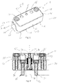
- FIG. 1 is a perspective illustration of an embodiment of the clamping device
- FIG. 2 is a cross-section along A-A in FIG. 1
- FIG. 3 is a cross section along B-B in FIG. 1
- FIG. 4 is a perspective illustration of a tool plate with a mounted mold
- FIG. 5 is a schematic partial cross-section through the intermediate support block 114 ′ mounted on the tool holder 100 .
- FIG. 1 a clamping device 1 according to the invention.
- the clamping device comprises two parts: an upper part 10 and a lower part 20 .
- the lower part 20 is provided with a mounting surface 21 (not visible), suitable to be arranged flat against the tool plate, as will be explained with reference to FIG. 4 .
- the lower part 20 has first 22 , second 23 , third 24 and fourth 25 side surfaces upstanding from said mounting surface 21 .
- the upper part 10 has first 11 , second 12 , third 13 and fourth 14 side surfaces.
- the upper and lower parts 10 , 20 are movably connected by a first bolt 30 , where the bolt's axis 38 of symmetry defines an axis, see FIG. 2 .
- FIG. 2 a cross-section through a clamping device is illustrated substantially through the cross-section A-A indicated in FIG. 1 .
- the same features are provided with the same reference numbers.
- a resilient member 40 is arranged in connection with the first bolt 30 between the upper and lower parts 10 , 20 .
- the resilient member may be any suitable construction, but in this embodiment a helical spring 40 is arranged concentrically with the bolt's 30 axis 38 .
- the first bolt 30 is provided with a non-threaded section 31 and a threaded section 32 .
- the threaded section 32 is fastened in the upper part 10 , whereas the lower part 20 is provided with a non-threaded section 31 .
- the hole 33 may have a diameter such that the interior surface of the hole 33 does not engage the bolt 30 .
- the resilient member 40 is arranged around the bolt 30 , a cavity 34 is provided, in this example partly in the upper and partly in the lower part 10 , 20 . In this manner the lower part or upper part 10 , 20 may move along the bolt 30 in the direction of the axis 38 . The movement is controlled by the bolt, such that the upper and lower parts 10 , 20 move along the axis 38 of the bolt, but is also limited by the bolt such that the parts do not separate when used.
- the resilient member when unloaded retains a distance x (see FIG. 3 ) between the upper and lower parts 10 , 20 .
- FIG. 3 illustrates a situation where the upper and lower parts 10 , 20 are forced together, the off-set y is indicated for illustrative purposes. It is clear that in the unloaded situation y will be smaller, as the upper part moves (upwards) along the oblique surfaces, thereby causing a lateral movement of the surface 13 .
- FIG. 3 is illustrated that at least a part 22 ′, hereinafter referred to as the first oblique surface of said first side surface 22 of the lower part 20 , is arranged at an oblique angle ⁇ with respect to the axis 38 , and that at least part 11 ′, hereinafter referred to as the second oblique surface, of said first surface 11 of the upper part 10 is arranged with an oblique angle ⁇ .
- the first and second oblique surfaces 22 ′, 11 ′ are facing each other and are parallel.
- the lower part's oblique surface 22 ′ will urge the upper part's oblique surface 11 ′ to be parallelly offset, in other words a lateral off-set relative to the axis and the plane of the first surface fastening bolts will occur.
- the distance y increases.
- a first set of fastening bolts 51 , 52 are provided for fastening the clamping device to a tool plate (not illustrated).
- Blind bores 51 ′, 52 ′ are provided in the upper part 10 , such that it is possible to tighten/loosen the bolts 51 , 52 without having to dismantle the clamping device.
- a second set of fastening bolts 53 , 54 is provided.
- the upper part 10 is forced towards the lower part 20 .
- the parts 10 , 20 engage this will occur as a sliding movement between the oblique surfaces 11 ′, 22 ′. Due to the oblique angle ⁇ , lateral displacement (relative to the axis 38 ) of the upper and lower parts 10 , 20 will occur.
- the lower part by means of the bolts 51 , 52 is fastened to the tool plate the side surface 13 of the upper part 10 will be laterally displaced, and thereby engage the mold (not illustrated).
- the second set of fastening bolts 53 , 54 will only be loosened slightly—just enough for the side surface 13 to disengage from the mold. If the second set of fastening bolts is removed altogether, the upper and lower parts 10 , 20 will still be held together by the bolt 30 .
- a slot 60 is provided, such that a tool, for example a screw driver may be used to pry the two parts 10 , 20 apart.
- a tool for example a screw driver may be used to pry the two parts 10 , 20 apart.
- FIG. 4 an assembly is illustrated. On a tool holding plate 100 two half-molds 110 , 111 are arranged. In the illustrated embodiment the molds each have three cavities, suitable to mold three objects each per cycle.
- a polymer distribution block 113 On the tool plate are provided permanent “0” positions 112 . Between the two molds is a polymer distribution block 113 . This is where the runner will form. Along one side of the molds 110 , 111 are provided fixed side limit-blocks, also referred to as molding tool holders 114 . Together with the distribution block 113 , they fix a corner 111 ′ correctly with respect to the “0” position 112 .
- clamping devices 1 , 1 ′ are arranged along the two free sides of each mold 110 , 111 .
- the clamping devices 1 ′ are arranged in intermediate support blocks 114 ′.
- the clamping devices 1 , 1 ′ may be arranged in cavities (not illustrated) cut in the tool holding plate 100 , where the threaded holes for receiving the bolts 51 , 52 is provided in the bottom of the cavity.
- the molds 110 , 111 are positioned abutting the tool holders 114 and the block 113 .
- the clamping devices 1 , 1 ′ are by means of the first fastening bolts 51 , 52 fastened on the tool holding plate 100 .
- the second set of fastening bolts 53 , 54 are then tightened whereby the lateral displacement of the upper part 10 of the clamping device is effected. This lateral displacement forces the mold into firm engagement with the holder 114 and block 113 , such that the mold is precisely positioned and securely held on the tool holding plate 100 .
- the second set of fastening bolts 53 , 54 is unscrewed at least partly.
- the resilient member maybe aided by the screw driver prying in the slot 60 , urges the upper and lower parts 10 , 20 apart, such that the upper part 10 is laterally pushed away from the mold, which thereafter is loose and can easily be removed.
- FIG. 5 is a schematic partial cross-section through the intermediate support block 114 ′ mounted on the tool holder 100 .
- the mounting means are in the shape of bolts 115 . Also illustrated are the holes 116 that are designed to receive the bolts 115 which mount the clamping device 1 to the intermediate support block 114 ′.
Landscapes
- Engineering & Computer Science (AREA)
- Mechanical Engineering (AREA)
- Manufacturing & Machinery (AREA)
- Moulds For Moulding Plastics Or The Like (AREA)
Abstract
Description
Claims (10)
Applications Claiming Priority (2)
| Application Number | Priority Date | Filing Date | Title |
|---|---|---|---|
| DKPA201870499 | 2018-07-23 | ||
| DKPA201870499 | 2018-07-23 |
Publications (2)
| Publication Number | Publication Date |
|---|---|
| US20200023563A1 US20200023563A1 (en) | 2020-01-23 |
| US11376775B2 true US11376775B2 (en) | 2022-07-05 |
Family
ID=67180627
Family Applications (1)
| Application Number | Title | Priority Date | Filing Date |
|---|---|---|---|
| US16/519,151 Active 2039-08-16 US11376775B2 (en) | 2018-07-23 | 2019-07-23 | Easy clamp |
Country Status (2)
| Country | Link |
|---|---|
| US (1) | US11376775B2 (en) |
| EP (1) | EP3599054A1 (en) |
Families Citing this family (2)
| Publication number | Priority date | Publication date | Assignee | Title |
|---|---|---|---|---|
| GB202012913D0 (en) * | 2020-08-18 | 2020-09-30 | Three G Metal Fabrications Ltd | Modular platform system components |
| CN113119407B (en) * | 2021-04-26 | 2022-12-16 | 江西联益光学有限公司 | Injection mold suitable for machining internal thread plastic part |
Citations (9)
| Publication number | Priority date | Publication date | Assignee | Title |
|---|---|---|---|---|
| JPS6482914A (en) | 1987-09-26 | 1989-03-28 | Nissei Plastics Ind Co | Mold device |
| JPH0229020A (en) | 1988-07-18 | 1990-01-31 | Victor Co Of Japan Ltd | Median filter |
| US5226637A (en) * | 1991-03-26 | 1993-07-13 | Aioi Seiki, Inc. | Clamping device |
| US6126158A (en) * | 1998-11-23 | 2000-10-03 | Engibarov; Eddy | Soft jaw for a machine vise |
| WO2007099763A1 (en) | 2006-02-28 | 2007-09-07 | Zeon Corporation | Injection molding die |
| US20070284796A1 (en) | 2006-06-07 | 2007-12-13 | Hummel Richard M | Clamping mechanism |
| EP1946903A1 (en) | 2007-01-22 | 2008-07-23 | Samsung Electronics Co., Ltd. | Injection molding apparatus |
| EP2735419A1 (en) | 2012-11-26 | 2014-05-28 | Rainer Knarr | Fine centring unit for tool and mould making, its use in a moulding device for the moulding of moulded articles and moulding device equipped therewith for moulding moulded articles |
| CN106945233A (en) | 2017-03-27 | 2017-07-14 | 苏州大友汽车配套件有限公司 | A kind of air door panel injection mold of car duct plate |
Family Cites Families (2)
| Publication number | Priority date | Publication date | Assignee | Title |
|---|---|---|---|---|
| JPS5944978B2 (en) | 1979-07-03 | 1984-11-02 | トヨタ自動車株式会社 | Injection mold insert positioning method |
| JPH0733041B2 (en) | 1989-03-02 | 1995-04-12 | 日精樹脂工業株式会社 | Nesting mold and mounting method |
-
2019
- 2019-07-04 EP EP19184379.6A patent/EP3599054A1/en not_active Withdrawn
- 2019-07-23 US US16/519,151 patent/US11376775B2/en active Active
Patent Citations (9)
| Publication number | Priority date | Publication date | Assignee | Title |
|---|---|---|---|---|
| JPS6482914A (en) | 1987-09-26 | 1989-03-28 | Nissei Plastics Ind Co | Mold device |
| JPH0229020A (en) | 1988-07-18 | 1990-01-31 | Victor Co Of Japan Ltd | Median filter |
| US5226637A (en) * | 1991-03-26 | 1993-07-13 | Aioi Seiki, Inc. | Clamping device |
| US6126158A (en) * | 1998-11-23 | 2000-10-03 | Engibarov; Eddy | Soft jaw for a machine vise |
| WO2007099763A1 (en) | 2006-02-28 | 2007-09-07 | Zeon Corporation | Injection molding die |
| US20070284796A1 (en) | 2006-06-07 | 2007-12-13 | Hummel Richard M | Clamping mechanism |
| EP1946903A1 (en) | 2007-01-22 | 2008-07-23 | Samsung Electronics Co., Ltd. | Injection molding apparatus |
| EP2735419A1 (en) | 2012-11-26 | 2014-05-28 | Rainer Knarr | Fine centring unit for tool and mould making, its use in a moulding device for the moulding of moulded articles and moulding device equipped therewith for moulding moulded articles |
| CN106945233A (en) | 2017-03-27 | 2017-07-14 | 苏州大友汽车配套件有限公司 | A kind of air door panel injection mold of car duct plate |
Non-Patent Citations (1)
| Title |
|---|
| European Search Report dated Dec. 13, 2019 in European Application No. 19 18 4379, 3 pages. |
Also Published As
| Publication number | Publication date |
|---|---|
| US20200023563A1 (en) | 2020-01-23 |
| EP3599054A1 (en) | 2020-01-29 |
Similar Documents
| Publication | Publication Date | Title |
|---|---|---|
| US4828479A (en) | Molding apparatus | |
| US4959002A (en) | Inserts for injection mold machine | |
| KR100489285B1 (en) | Cutting tool with clamping device | |
| US11376775B2 (en) | Easy clamp | |
| JP5591819B2 (en) | Clamp system | |
| CN102574214A (en) | Modular structure for supporting blanks | |
| JP3563035B2 (en) | Multi-stage molding machine with connecting tool block | |
| TWM635115U (en) | Vise quick change base improved structure | |
| US6540499B2 (en) | Modular mold assembly | |
| US4185935A (en) | Coupling apparatus | |
| KR101243290B1 (en) | Movable die unit for die-casting | |
| CN210586949U (en) | Female die fastening device of cylindrical closed forging die | |
| CN210760336U (en) | Bolt-free contact line positioning wire clamp | |
| KR101919937B1 (en) | Jig for hole processing of injection mold parts | |
| CN110394413B (en) | Female die fastening device of cylindrical closed forging die | |
| CN111571942B (en) | Mold structure capable of quickly replacing insert | |
| JP3288975B2 (en) | Cassette type mold device | |
| CN223834008U (en) | Quick clamping tool for square steel | |
| JP2649444B2 (en) | Mold mounting equipment for molding machines | |
| KR101303668B1 (en) | A bite holder, an assebly of a bite holder and a bite holder fixture, and a metod of mounting of a bite for accurate mounting of the bite | |
| CN223441672U (en) | A support block clamping tool | |
| CN112077760A (en) | Divide processing anchor clamps and processing equipment in | |
| KR102439139B1 (en) | car license plate fixture | |
| CN110181306A (en) | Shell processing jig | |
| KR200264276Y1 (en) | Tool module clamping apparatus |
Legal Events
| Date | Code | Title | Description |
|---|---|---|---|
| FEPP | Fee payment procedure |
Free format text: ENTITY STATUS SET TO UNDISCOUNTED (ORIGINAL EVENT CODE: BIG.); ENTITY STATUS OF PATENT OWNER: LARGE ENTITY |
|
| STPP | Information on status: patent application and granting procedure in general |
Free format text: DOCKETED NEW CASE - READY FOR EXAMINATION |
|
| AS | Assignment |
Owner name: AMMERAAL BELTECH MODULAR A/S, DENMARK Free format text: ASSIGNMENT OF ASSIGNORS INTEREST;ASSIGNOR:ANDERSEN, KENNETH WESTERGAARD;REEL/FRAME:053406/0119 Effective date: 20200804 |
|
| STPP | Information on status: patent application and granting procedure in general |
Free format text: NON FINAL ACTION MAILED |
|
| STPP | Information on status: patent application and granting procedure in general |
Free format text: RESPONSE TO NON-FINAL OFFICE ACTION ENTERED AND FORWARDED TO EXAMINER |
|
| STPP | Information on status: patent application and granting procedure in general |
Free format text: FINAL REJECTION MAILED |
|
| STPP | Information on status: patent application and granting procedure in general |
Free format text: DOCKETED NEW CASE - READY FOR EXAMINATION |
|
| STPP | Information on status: patent application and granting procedure in general |
Free format text: NOTICE OF ALLOWANCE MAILED -- APPLICATION RECEIVED IN OFFICE OF PUBLICATIONS |
|
| STPP | Information on status: patent application and granting procedure in general |
Free format text: PUBLICATIONS -- ISSUE FEE PAYMENT VERIFIED |
|
| STCF | Information on status: patent grant |
Free format text: PATENTED CASE |
|
| MAFP | Maintenance fee payment |
Free format text: PAYMENT OF MAINTENANCE FEE, 4TH YEAR, LARGE ENTITY (ORIGINAL EVENT CODE: M1551); ENTITY STATUS OF PATENT OWNER: LARGE ENTITY Year of fee payment: 4 |