US11375673B2 - Landscape edging with a stone surface and manufacturing method and installation system thereof - Google Patents
Landscape edging with a stone surface and manufacturing method and installation system thereof Download PDFInfo
- Publication number
- US11375673B2 US11375673B2 US16/330,054 US201616330054A US11375673B2 US 11375673 B2 US11375673 B2 US 11375673B2 US 201616330054 A US201616330054 A US 201616330054A US 11375673 B2 US11375673 B2 US 11375673B2
- Authority
- US
- United States
- Prior art keywords
- edging
- plate
- landscape edging
- stone
- stone surface
- Prior art date
- Legal status (The legal status is an assumption and is not a legal conclusion. Google has not performed a legal analysis and makes no representation as to the accuracy of the status listed.)
- Active, expires
Links
Images


Classifications
-
- A—HUMAN NECESSITIES
- A01—AGRICULTURE; FORESTRY; ANIMAL HUSBANDRY; HUNTING; TRAPPING; FISHING
- A01G—HORTICULTURE; CULTIVATION OF VEGETABLES, FLOWERS, RICE, FRUIT, VINES, HOPS OR SEAWEED; FORESTRY; WATERING
- A01G9/00—Cultivation in receptacles, forcing-frames or greenhouses; Edging for beds, lawn or the like
- A01G9/28—Raised beds; Planting beds; Edging elements for beds, lawn or the like, e.g. tiles
-
- B—PERFORMING OPERATIONS; TRANSPORTING
- B32—LAYERED PRODUCTS
- B32B—LAYERED PRODUCTS, i.e. PRODUCTS BUILT-UP OF STRATA OF FLAT OR NON-FLAT, e.g. CELLULAR OR HONEYCOMB, FORM
- B32B11/00—Layered products comprising a layer of bituminous or tarry substances
- B32B11/02—Layered products comprising a layer of bituminous or tarry substances with fibres or particles being present as additives in the layer
-
- B—PERFORMING OPERATIONS; TRANSPORTING
- B32—LAYERED PRODUCTS
- B32B—LAYERED PRODUCTS, i.e. PRODUCTS BUILT-UP OF STRATA OF FLAT OR NON-FLAT, e.g. CELLULAR OR HONEYCOMB, FORM
- B32B11/00—Layered products comprising a layer of bituminous or tarry substances
- B32B11/04—Layered products comprising a layer of bituminous or tarry substances comprising such bituminous or tarry substance as the main or only constituent of a layer, which is next to another layer of the same or of a different material
- B32B11/08—Layered products comprising a layer of bituminous or tarry substances comprising such bituminous or tarry substance as the main or only constituent of a layer, which is next to another layer of the same or of a different material of metal
-
- B—PERFORMING OPERATIONS; TRANSPORTING
- B32—LAYERED PRODUCTS
- B32B—LAYERED PRODUCTS, i.e. PRODUCTS BUILT-UP OF STRATA OF FLAT OR NON-FLAT, e.g. CELLULAR OR HONEYCOMB, FORM
- B32B11/00—Layered products comprising a layer of bituminous or tarry substances
- B32B11/10—Layered products comprising a layer of bituminous or tarry substances next to a fibrous or filamentary layer
-
- B—PERFORMING OPERATIONS; TRANSPORTING
- B32—LAYERED PRODUCTS
- B32B—LAYERED PRODUCTS, i.e. PRODUCTS BUILT-UP OF STRATA OF FLAT OR NON-FLAT, e.g. CELLULAR OR HONEYCOMB, FORM
- B32B15/00—Layered products comprising a layer of metal
- B32B15/02—Layer formed of wires, e.g. mesh
-
- B—PERFORMING OPERATIONS; TRANSPORTING
- B32—LAYERED PRODUCTS
- B32B—LAYERED PRODUCTS, i.e. PRODUCTS BUILT-UP OF STRATA OF FLAT OR NON-FLAT, e.g. CELLULAR OR HONEYCOMB, FORM
- B32B15/00—Layered products comprising a layer of metal
- B32B15/14—Layered products comprising a layer of metal next to a fibrous or filamentary layer
-
- B—PERFORMING OPERATIONS; TRANSPORTING
- B32—LAYERED PRODUCTS
- B32B—LAYERED PRODUCTS, i.e. PRODUCTS BUILT-UP OF STRATA OF FLAT OR NON-FLAT, e.g. CELLULAR OR HONEYCOMB, FORM
- B32B15/00—Layered products comprising a layer of metal
- B32B15/20—Layered products comprising a layer of metal comprising aluminium or copper
-
- B—PERFORMING OPERATIONS; TRANSPORTING
- B32—LAYERED PRODUCTS
- B32B—LAYERED PRODUCTS, i.e. PRODUCTS BUILT-UP OF STRATA OF FLAT OR NON-FLAT, e.g. CELLULAR OR HONEYCOMB, FORM
- B32B19/00—Layered products comprising a layer of natural mineral fibres or particles, e.g. asbestos, mica
- B32B19/06—Layered products comprising a layer of natural mineral fibres or particles, e.g. asbestos, mica next to a fibrous or filamentary layer
-
- B—PERFORMING OPERATIONS; TRANSPORTING
- B32—LAYERED PRODUCTS
- B32B—LAYERED PRODUCTS, i.e. PRODUCTS BUILT-UP OF STRATA OF FLAT OR NON-FLAT, e.g. CELLULAR OR HONEYCOMB, FORM
- B32B3/00—Layered products comprising a layer with external or internal discontinuities or unevennesses, or a layer of non-planar shape; Layered products comprising a layer having particular features of form
- B32B3/02—Layered products comprising a layer with external or internal discontinuities or unevennesses, or a layer of non-planar shape; Layered products comprising a layer having particular features of form characterised by features of form at particular places, e.g. in edge regions
- B32B3/08—Layered products comprising a layer with external or internal discontinuities or unevennesses, or a layer of non-planar shape; Layered products comprising a layer having particular features of form characterised by features of form at particular places, e.g. in edge regions characterised by added members at particular parts
-
- B—PERFORMING OPERATIONS; TRANSPORTING
- B32—LAYERED PRODUCTS
- B32B—LAYERED PRODUCTS, i.e. PRODUCTS BUILT-UP OF STRATA OF FLAT OR NON-FLAT, e.g. CELLULAR OR HONEYCOMB, FORM
- B32B33/00—Layered products characterised by particular properties or particular surface features, e.g. particular surface coatings; Layered products designed for particular purposes not covered by another single class
-
- B—PERFORMING OPERATIONS; TRANSPORTING
- B32—LAYERED PRODUCTS
- B32B—LAYERED PRODUCTS, i.e. PRODUCTS BUILT-UP OF STRATA OF FLAT OR NON-FLAT, e.g. CELLULAR OR HONEYCOMB, FORM
- B32B5/00—Layered products characterised by the non- homogeneity or physical structure, i.e. comprising a fibrous, filamentary, particulate or foam layer; Layered products characterised by having a layer differing constitutionally or physically in different parts
- B32B5/02—Layered products characterised by the non- homogeneity or physical structure, i.e. comprising a fibrous, filamentary, particulate or foam layer; Layered products characterised by having a layer differing constitutionally or physically in different parts characterised by structural features of a fibrous or filamentary layer
- B32B5/022—Non-woven fabric
-
- B—PERFORMING OPERATIONS; TRANSPORTING
- B32—LAYERED PRODUCTS
- B32B—LAYERED PRODUCTS, i.e. PRODUCTS BUILT-UP OF STRATA OF FLAT OR NON-FLAT, e.g. CELLULAR OR HONEYCOMB, FORM
- B32B7/00—Layered products characterised by the relation between layers; Layered products characterised by the relative orientation of features between layers, or by the relative values of a measurable parameter between layers, i.e. products comprising layers having different physical, chemical or physicochemical properties; Layered products characterised by the interconnection of layers
- B32B7/04—Interconnection of layers
- B32B7/12—Interconnection of layers using interposed adhesives or interposed materials with bonding properties
-
- B—PERFORMING OPERATIONS; TRANSPORTING
- B32—LAYERED PRODUCTS
- B32B—LAYERED PRODUCTS, i.e. PRODUCTS BUILT-UP OF STRATA OF FLAT OR NON-FLAT, e.g. CELLULAR OR HONEYCOMB, FORM
- B32B2305/00—Condition, form or state of the layers or laminate
- B32B2305/10—Fibres of continuous length
- B32B2305/18—Fabrics, textiles
-
- B—PERFORMING OPERATIONS; TRANSPORTING
- B32—LAYERED PRODUCTS
- B32B—LAYERED PRODUCTS, i.e. PRODUCTS BUILT-UP OF STRATA OF FLAT OR NON-FLAT, e.g. CELLULAR OR HONEYCOMB, FORM
- B32B2311/00—Metals, their alloys or their compounds
-
- B—PERFORMING OPERATIONS; TRANSPORTING
- B32—LAYERED PRODUCTS
- B32B—LAYERED PRODUCTS, i.e. PRODUCTS BUILT-UP OF STRATA OF FLAT OR NON-FLAT, e.g. CELLULAR OR HONEYCOMB, FORM
- B32B2318/00—Mineral based
- B32B2318/04—Stone
-
- B—PERFORMING OPERATIONS; TRANSPORTING
- B32—LAYERED PRODUCTS
- B32B—LAYERED PRODUCTS, i.e. PRODUCTS BUILT-UP OF STRATA OF FLAT OR NON-FLAT, e.g. CELLULAR OR HONEYCOMB, FORM
- B32B2395/00—Bituminous material, e.g. tar, asphalt
-
- B—PERFORMING OPERATIONS; TRANSPORTING
- B32—LAYERED PRODUCTS
- B32B—LAYERED PRODUCTS, i.e. PRODUCTS BUILT-UP OF STRATA OF FLAT OR NON-FLAT, e.g. CELLULAR OR HONEYCOMB, FORM
- B32B2410/00—Agriculture-related articles
-
- B—PERFORMING OPERATIONS; TRANSPORTING
- B32—LAYERED PRODUCTS
- B32B—LAYERED PRODUCTS, i.e. PRODUCTS BUILT-UP OF STRATA OF FLAT OR NON-FLAT, e.g. CELLULAR OR HONEYCOMB, FORM
- B32B2451/00—Decorative or ornamental articles
Definitions
- the invention relates to a separation edging for separating different vegetations or vegetation from paths in gardens, parks, etc., in particular to a landscape edging with a stone surface and a manufacture method and an install system thereof.
- JP09-107797A discloses an isolation edging for a flowerbed, which serves only as an isolation and cannot be well integrated with the surrounding environment.
- the invention provides a landscape edging with a stone surface and manufacture methods and install system thereof, which mainly solves the problems of poor shaping effect, high cost and poor fusion with vegetation of the current landscape edging.
- a landscape edging with a stone surface including an edging body which has flexibility and the outer wall thereof is provided with a decorative layer made of stone particles;
- the edging body includes a first plate and a second plate, wherein a flexible layer is disposed therebetween; the two ends of the flexible layer are respectively bonded with the first plate and the second plate;
- one end of the first plate and the second plate is integrally disposed
- the edging body includes an upper end surface arranged at the top, and a first side surface and a second side surface disposed on both sides; the upper end surface, the first side surface and the second side surface are respectively provided with the decorative layer;
- the decorative layer is formed by bonding stone particles
- the first plate and the second plate are made of a non-woven fabric as a base;
- the flexible layer is an asphalt layer
- a metal reinforcing wire mesh is further disposed between the first plate and the second plate;
- the decorative layer is disposed at the upper end of the edging body, and the lower end of the edging body is provided with an insertion portion inserted into the soil.
- a manufacture method for making the landscape edging with a stone surface comprising the following steps of:
- step 1 Gluing: coating an adhesive on one side of a base material;
- step 2 Paving stones: paving screened stone particles on the base material and bonding by the adhesive;
- step 3 Flattening stones: flattening the paved stone particles by a flat tool
- step 4 Picking stones: removing redundant stones
- step 5 Coagulating gel: standing for 20 to 30 hours for the adhesive to set;
- step 6 Molding: applying the heated asphalt mixture to the other side of the base material, and folding the base material and bonding together by the asphalt mixture to produce the edging body.
- the asphalt mixture comprises 20%-40% of bitumen, 5%-20% of a flexible substrate and 55%-75% of a filler in mass percentage.
- the flexible substrate is SBS or styrene butadiene rubber or styrene-ethylene/butylene-styrene block copolymer (SEBS) or styrene ethylene/propylene-styrene block copolymer or polyisoprene.
- SEBS styrene-ethylene/butylene-styrene block copolymer
- SEBS styrene-ethylene/propylene-styrene block copolymer or polyisoprene
- the filler is calcium carbonate powder or wollastonite.
- the stone particles were screened by a sieve having a pore size of 1 to 5 mm.
- a install system for installing the landscape edging with a stone surface comprising a installing bracket, wherein one end of the installing bracket is provided with a fixing pile inserted into the soil, and the other end is provided with a installing groove detachably matched with the edging body.
- the outer wall of the fixing pile is provided with a plurality of barbs.
- the inner walls of the two sides of the installing groove are correspondingly provided with snap protrusions.
- the snap protrusion has a trapezoidal cross section.
- the bottom of the fixing pile has a triangular cross section.
- the intermediate shaft of the fixing pile and the intermediate shaft of the installing groove are eccentrically disposed.
- the side of the barb is provided with an arc-shaped surface.
- connecting member for joining adjacent two edging bodies; the connecting member is provided with a clamping groove for gripping the edging body.
- the inner wall of the clamping groove is further provided with clamping teeth.
- the invention has the beneficial effects that the invention provides a landscape edging with a stone surface and install system, comprising an edging body that has flexibility and the outer wall thereof is provided with a decorative layer made of stone particles.
- the isolation edging can be well integrated into the surrounding environment when being used, and it has a certain flexibility, can be better shaped and has a better effect. It is a good alternative for the existing landscape edging.
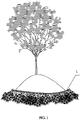
- FIG. 1 is a schematic view showing the state of use of one embodiment of the present invention.
- FIG. 2 is a schematic perspective view of one embodiment of the present invention.
- FIG. 3 is a flattened schematic view of one embodiment of the present invention.
- FIG. 4 is a schematic view of one embodiment of the present invention.
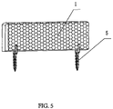
- FIG. 5 is a schematic perspective view of one embodiment of the present invention mounted with a installing bracket.
- FIG. 6 is a schematic cross-sectional view of one embodiment of the present invention.
- FIG. 7 is a schematic perspective view of a installing bracket according to one embodiment of the present invention.
- FIG. 8 is a schematic perspective view of one embodiment of the present invention with the connecting member and installing bracket mounted together.
- FIG. 9 is a schematic perspective view of a connecting member according to one embodiment of the present invention.
- FIG. 10 is a schematic cross-sectional view of a connecting member according to another embodiment of the present invention.
- FIG. 11 is a schematic perspective view of a connecting member according to another embodiment of the present invention.
- a landscape edging with a stone surface comprising an edging body ( 1 ) having flexibility and the outer wall thereof is provided with a decorative layer ( 2 ) made of stone particles.
- the decorative layer herein may be made of various materials, such as pebbles, gravel particles, etc. These stones may be natural stones or artificially processed stones, and may be selected according to different scenes.
- the edging body has flexibility, and the edging body itself may be made of a flexible material, or may be provided with a flexible additive layer.
- the flexible material herein may be aluminum, flexible plastic or the like.
- the edging body may be in various shapes such as strip shape, wave shape and the like, and may be selected according to actual requirements.
- the invention provides a landscape edging with a stone surface and manufacture methods and install system thereof, comprising an edging body having flexibility and the outer wall thereof is provided with a decorative layer.
- the decorative layer may be made of stone, so that the isolation edging can be well integrated into the surrounding environment when being used.
- the isolation edging has a certain flexibility, which can be better shaped and has a better effect. It is a good alternative for the existing landscape edging.
- the edging body includes a first plate 11 and a second plate 12 , wherein a flexible layer 16 is disposed therebetween; the two ends of the flexible layer 16 are respectively bonded with the first plate 11 and the second plate 12 .
- the edging body is formed by bonding the first plate and the second plate, wherein the first plate and the second plate may be two separate plates, or may have a structure similar to a greeting card; as shown in FIG. 2 , the first plate and the second plate have the structure in which the edging body is flattened, wherein the flexible layer may be a layer of adhesive material, or may be coated with adhesive on both ends of the additional intermediate plate.
- the flexible layer may be a layer of adhesive material, or may be coated with adhesive on both ends of the additional intermediate plate.
- first plate 11 and the second plate 12 are integrally disposed.
- first plate and the second plate in the application have a structure in which the edging body is flattened.
- the edging body 1 includes an upper end surface 15 arranged at the top, and a first side surface 13 and a second side surface 14 disposed on both sides; the upper end surface 15 , the first side surface 13 and the second side surface 14 are respectively provided with the decorative layer 2 .
- the edging body in the patent has an elongated strip shape, and the upper end surface and the side surfaces on both sides are provided with a decorative layer, so that a three-dimensional decorative effect can be achieved; compared with the prior art that most of the conventional prior art are single-sided material structures, an unexpected effect is achieved.
- the edging body can be better integrated with the environment by matching optional materials.
- the first plate 11 and the second plate 12 are made of a non-woven fabric as a base.
- the non-woven fabric has the characteristics of moisture resistance, air permeability, flexibility, light weight, no combustion supporting, easy decomposition, no toxicity, no irritation, low price, recyclability and the like.
- the product thus prepared is light in weight, low in cost and convenient to use.
- a metal reinforcing wire mesh 19 is further disposed between the first plate 11 and the second plate 12 , which increases toughness, stability and service life.
- the decorative layer 2 is disposed at the upper end of the edging body 1 , and the lower end of the edging body 1 is provided with an insertion portion 18 inserted into the soil.
- the upper portion of the edging body is provided with a layer on the exposed surface, and the lower portion is inserted into the soil without a decorative layer for material saving.
- the flexible layer is an asphalt layer.
- the asphalt is used for adhesion in the patent with bonding and shaping effect, and the molding effect is better.
- a manufacture method for making the landscape edging with a stone surface characterized in that comprising the following steps of:
- step 1 Gluing: coating an adhesive on the outer surface of a base material;
- step 2 Paving stones: paving screened stone particles on the outer surface of the base material and bonding by the adhesive;
- step 3 Flattening stones: flattening the paved stone particles by a flat tool
- step 4 Picking stones: removing redundant stones
- step 5 Coagulating gel: standing for 20 to 30 hours for the adhesive to set;
- step 6 Molding: applying the heated asphalt mixture to the outer surface of the base material, and folding the base material and bonding together by the asphalt mixture to produce the edging body.
- the edging body prepared thereby is light in weight and convenient for molding.
- the asphalt mixture comprises 20%-40% of bitumen, 5%-20% of a flexible substrate and 55%-75% of a filler in mass percentage.
- the flexible substrate is SBS or styrene butadiene rubber or styrene-ethylene/butylene-styrene block copolymer (SEBS), styrene ethylene/propylene-styrene block copolymer (SEPS) or polyisoprene.
- SEBS styrene butadiene rubber
- SEPS styrene ethylene/propylene-styrene block copolymer
- polyisoprene polyisoprene
- the filler is calcium carbonate powder or wollastonite.
- the stone particles were screened by a sieve having a pore size of 1 to 5 mm. On the one hand, The stone screened thereby is convenient to process; on the other hand, it is more attractive and convenient for usage.
- a install system for installing the landscape edging with a stone surface comprising a installing bracket 5 , wherein one end of the installing bracket 5 is provided with a fixing pile 51 inserted into the soil, and the other end is provided with a installing groove 52 detachably matched with the edging body 1 .
- the installing bracket here is used to insert the fixing pile into the soil for fixing, and the edging body is installed in the installing groove.
- the edging body is installed by the snap fit; the dimension in the width direction of the edging body is matched with the width of the installing groove to form a snap fit, which is convenient to disassemble and assemble, and the effect in use is excellent.
- the outer wall of the fixing pile 51 is provided with a plurality of barbs 511 which prevent accidental release when the fixing pile is inserted into the soil, and the installation is more stable.
- the inner walls of the two sides of the installing groove 52 are correspondingly provided with snap protrusions 521 .
- the snap protrusions are abutted on two sides of the edging body to further enhance the stability and convenience of the installation.
- the snap protrusion 521 has a trapezoidal cross section.
- the trapezoid has an inclined surface with the function of guiding and sliding when the edging body is clamped and installed, and the function of falling prevention after the edging body is installed in place; it is convenient to install and stable in use.
- the bottom of the fixing pile 51 has a triangular cross section, so that it is more convenient to be inserted into the soil with small resistance.
- the intermediate shaft of the fixing pile 51 and the intermediate shaft of the installing groove 52 are eccentrically disposed.
- the intermediate shaft as the preferred fixing pile is eccentrically disposed with the intermediate shaft of the installing groove, so that when the installing bracket is to be mounted after the edging body is mounted in the installing groove, it is convenient for installation without occlusion.
- the side of the barb 511 is provided with an arc-shaped surface 512 , so that it is smoother and more convenient to insert the fixing pile into the soil.
- a connecting member 8 for joining adjacent two edging bodies 1 ; the connecting member 8 is provided with a clamping groove 81 for gripping the edging body 1 .
- the connecting member can be used for joining two adjacent edging bodies, which makes the assembly more stable.
- the inner wall of the clamping groove 81 is further provided with clamping teeth 82 . Being fixed by clamping teeth makes installation easier.
Landscapes
- Life Sciences & Earth Sciences (AREA)
- Environmental Sciences (AREA)
- Engineering & Computer Science (AREA)
- Textile Engineering (AREA)
- Road Paving Structures (AREA)
- Revetment (AREA)
Abstract
Description
Claims (19)
Applications Claiming Priority (1)
| Application Number | Priority Date | Filing Date | Title |
|---|---|---|---|
| PCT/CN2016/103677 WO2018076257A1 (en) | 2016-10-28 | 2016-10-28 | Landscape edging used on stone surface, and manufacturing method and installation system therefor |
Publications (2)
| Publication Number | Publication Date |
|---|---|
| US20190223392A1 US20190223392A1 (en) | 2019-07-25 |
| US11375673B2 true US11375673B2 (en) | 2022-07-05 |
Family
ID=62024241
Family Applications (1)
| Application Number | Title | Priority Date | Filing Date |
|---|---|---|---|
| US16/330,054 Active 2038-02-19 US11375673B2 (en) | 2016-10-28 | 2016-10-28 | Landscape edging with a stone surface and manufacturing method and installation system thereof |
Country Status (3)
| Country | Link |
|---|---|
| US (1) | US11375673B2 (en) |
| CN (1) | CN109561661A (en) |
| WO (1) | WO2018076257A1 (en) |
Citations (20)
| Publication number | Priority date | Publication date | Assignee | Title |
|---|---|---|---|---|
| US4543745A (en) * | 1984-05-18 | 1985-10-01 | Malcolm Beck | Multiple use decorative edging |
| US4647491A (en) * | 1984-12-07 | 1987-03-03 | Flexpak Co. | Corrugated landscaping edging |
| US5077944A (en) * | 1989-09-06 | 1992-01-07 | Ebi Producter Hb | Curbstone |
| US6622426B2 (en) | 2001-01-19 | 2003-09-23 | Easy Gardener, Inc. | Stackable landscape edging and methods of manufacturing and using same |
| US20050150158A1 (en) * | 2002-09-04 | 2005-07-14 | Fakhari M. J. | Fiberglass lawn edging with integral electrical conductor |
| US20060150480A1 (en) | 2005-01-12 | 2006-07-13 | Colorado Metal Craft, Inc. | Landscape edging system and methods of use |
| US20090064571A1 (en) * | 2002-09-04 | 2009-03-12 | John Fakhari | Lawn edging with integral electrical conductor and clip connectors |
| US20100050505A1 (en) * | 2008-09-03 | 2010-03-04 | Zwier Daniel G | Anchorless edging strip |
| CN102106240A (en) | 2009-12-29 | 2011-06-29 | 厦门万新橡胶有限公司 | Combined type environmentally-friendly non-toxic colorful rubber fence and manufacturing method thereof |
| US20110277395A1 (en) * | 2008-05-20 | 2011-11-17 | John Wink | Landscape edging system |
| US20120311927A1 (en) * | 2010-02-22 | 2012-12-13 | Bolin Joel W | Method and apparatus for landscape edging |
| US20150342124A1 (en) * | 2014-05-31 | 2015-12-03 | Dee Volin | Unique extrusion manufacturing method and unique soil-packing garden-shaping system, having adjustable elevation-guiding system, impact-absorbing system, adjustable penetration-guiding system, adjustable border-strengthening system, and shape-hardening system |
| US20160242364A1 (en) * | 2015-02-24 | 2016-08-25 | Keystone Retaining Wall Systems Llc | Edger having connection surfaces |
| US20170359967A1 (en) * | 2014-12-04 | 2017-12-21 | Sapgeo Llc | Textile barrier including aqueous super absorbent polymer composition |
| US20180027746A1 (en) * | 2016-07-27 | 2018-02-01 | Kent Stover | Plant edging |
| US20180206418A1 (en) * | 2016-07-27 | 2018-07-26 | Kent Stover | Plant edging |
| US20180255714A1 (en) * | 2015-01-12 | 2018-09-13 | EZ Concepts LLC | Simulated stone landscape edging |
| US20190186159A1 (en) * | 2017-12-15 | 2019-06-20 | Joseph Silvestro | Structural Rod Protective Device |
| US20200029509A1 (en) * | 2018-07-30 | 2020-01-30 | George Patrick Solis | Bracing and blocking apparatus for a variety of uses |
| US20200178480A1 (en) * | 2016-07-27 | 2020-06-11 | Kent Stover | Plant edging |
Family Cites Families (6)
| Publication number | Priority date | Publication date | Assignee | Title |
|---|---|---|---|---|
| AUPO502497A0 (en) * | 1997-02-07 | 1997-03-06 | Measday, Brian J | Tree surround |
| JP3010597B1 (en) * | 1998-08-31 | 2000-02-21 | 前田屋外美術株式会社 | Surface material for finishing granite and method for producing the surface material for finishing granite |
| US6811357B1 (en) * | 2002-07-30 | 2004-11-02 | Konrad Haug | Retaining wall assembly |
| CN1986250A (en) * | 2005-12-20 | 2007-06-27 | 刘小军 | Engineering facing material and its making process |
| CN103692719B (en) * | 2014-01-20 | 2015-04-22 | 辽宁大禹防水科技发展有限公司 | Composite pre-laid waterproof coiled material |
| CN204875441U (en) * | 2015-06-17 | 2015-12-16 | 深圳市立捷装饰设计工程有限公司 | Architectural decoration floor tile |
-
2016
- 2016-10-28 CN CN201680088421.1A patent/CN109561661A/en active Pending
- 2016-10-28 WO PCT/CN2016/103677 patent/WO2018076257A1/en not_active Ceased
- 2016-10-28 US US16/330,054 patent/US11375673B2/en active Active
Patent Citations (20)
| Publication number | Priority date | Publication date | Assignee | Title |
|---|---|---|---|---|
| US4543745A (en) * | 1984-05-18 | 1985-10-01 | Malcolm Beck | Multiple use decorative edging |
| US4647491A (en) * | 1984-12-07 | 1987-03-03 | Flexpak Co. | Corrugated landscaping edging |
| US5077944A (en) * | 1989-09-06 | 1992-01-07 | Ebi Producter Hb | Curbstone |
| US6622426B2 (en) | 2001-01-19 | 2003-09-23 | Easy Gardener, Inc. | Stackable landscape edging and methods of manufacturing and using same |
| US20050150158A1 (en) * | 2002-09-04 | 2005-07-14 | Fakhari M. J. | Fiberglass lawn edging with integral electrical conductor |
| US20090064571A1 (en) * | 2002-09-04 | 2009-03-12 | John Fakhari | Lawn edging with integral electrical conductor and clip connectors |
| US20060150480A1 (en) | 2005-01-12 | 2006-07-13 | Colorado Metal Craft, Inc. | Landscape edging system and methods of use |
| US20110277395A1 (en) * | 2008-05-20 | 2011-11-17 | John Wink | Landscape edging system |
| US20100050505A1 (en) * | 2008-09-03 | 2010-03-04 | Zwier Daniel G | Anchorless edging strip |
| CN102106240A (en) | 2009-12-29 | 2011-06-29 | 厦门万新橡胶有限公司 | Combined type environmentally-friendly non-toxic colorful rubber fence and manufacturing method thereof |
| US20120311927A1 (en) * | 2010-02-22 | 2012-12-13 | Bolin Joel W | Method and apparatus for landscape edging |
| US20150342124A1 (en) * | 2014-05-31 | 2015-12-03 | Dee Volin | Unique extrusion manufacturing method and unique soil-packing garden-shaping system, having adjustable elevation-guiding system, impact-absorbing system, adjustable penetration-guiding system, adjustable border-strengthening system, and shape-hardening system |
| US20170359967A1 (en) * | 2014-12-04 | 2017-12-21 | Sapgeo Llc | Textile barrier including aqueous super absorbent polymer composition |
| US20180255714A1 (en) * | 2015-01-12 | 2018-09-13 | EZ Concepts LLC | Simulated stone landscape edging |
| US20160242364A1 (en) * | 2015-02-24 | 2016-08-25 | Keystone Retaining Wall Systems Llc | Edger having connection surfaces |
| US20180027746A1 (en) * | 2016-07-27 | 2018-02-01 | Kent Stover | Plant edging |
| US20180206418A1 (en) * | 2016-07-27 | 2018-07-26 | Kent Stover | Plant edging |
| US20200178480A1 (en) * | 2016-07-27 | 2020-06-11 | Kent Stover | Plant edging |
| US20190186159A1 (en) * | 2017-12-15 | 2019-06-20 | Joseph Silvestro | Structural Rod Protective Device |
| US20200029509A1 (en) * | 2018-07-30 | 2020-01-30 | George Patrick Solis | Bracing and blocking apparatus for a variety of uses |
Also Published As
| Publication number | Publication date |
|---|---|
| WO2018076257A1 (en) | 2018-05-03 |
| CN109561661A (en) | 2019-04-02 |
| US20190223392A1 (en) | 2019-07-25 |
Similar Documents
| Publication | Publication Date | Title |
|---|---|---|
| CA2387115A1 (en) | Landscape edging system with stakes attached | |
| US6622426B2 (en) | Stackable landscape edging and methods of manufacturing and using same | |
| USD523447S1 (en) | Covered turf sprayer assembly | |
| WO2007005061A8 (en) | Multi-purpose portable lay-down post and fencing system | |
| US20130219784A1 (en) | Landscape edging assembly | |
| CN105756320A (en) | Outdoor floor and manufacturing method thereof | |
| US11375673B2 (en) | Landscape edging with a stone surface and manufacturing method and installation system thereof | |
| US20110308150A1 (en) | Lawn edging grass restraint | |
| USD514597S1 (en) | Synthetic turf groomer | |
| US20120204486A1 (en) | Prefabricated gardening apparatus | |
| CN201176552Y (en) | Greening floor tile | |
| KR20150007160A (en) | A weed prevention sheet of sidewalk block and constructing method using the same | |
| GB2582279A (en) | Lawn apparatus | |
| CN202705845U (en) | Landscape garden road surface paved by utilizing junked tires | |
| CN106245887A (en) | A kind of assembling type skirting board section bar component and installation method thereof | |
| CN107401702A (en) | Projecting Lamp | |
| CN2481798Y (en) | lighted fence | |
| CA2533097C (en) | Lawn edging device | |
| CN101793085A (en) | DIY floor with LED screen | |
| CN2346859Y (en) | Assembled plastic floor | |
| CN207407263U (en) | A kind of stereo snow flake ornament lamp | |
| CN206781147U (en) | A kind of gas permeability anti-slip carpet leather for being easy to cleaning | |
| KR20100038349A (en) | Band type plant box | |
| CN223647365U (en) | Indoor spliced anti-slip floor | |
| ATE430221T1 (en) | ROAD CEILING TO REDUCE NOISE FROM ROLLING ROAD TRAFFIC |
Legal Events
| Date | Code | Title | Description |
|---|---|---|---|
| FEPP | Fee payment procedure |
Free format text: ENTITY STATUS SET TO UNDISCOUNTED (ORIGINAL EVENT CODE: BIG.); ENTITY STATUS OF PATENT OWNER: SMALL ENTITY |
|
| FEPP | Fee payment procedure |
Free format text: ENTITY STATUS SET TO SMALL (ORIGINAL EVENT CODE: SMAL); ENTITY STATUS OF PATENT OWNER: SMALL ENTITY |
|
| STPP | Information on status: patent application and granting procedure in general |
Free format text: DOCKETED NEW CASE - READY FOR EXAMINATION |
|
| STPP | Information on status: patent application and granting procedure in general |
Free format text: NON FINAL ACTION MAILED |
|
| STPP | Information on status: patent application and granting procedure in general |
Free format text: RESPONSE TO NON-FINAL OFFICE ACTION ENTERED AND FORWARDED TO EXAMINER |
|
| STPP | Information on status: patent application and granting procedure in general |
Free format text: FINAL REJECTION MAILED |
|
| STPP | Information on status: patent application and granting procedure in general |
Free format text: RESPONSE AFTER FINAL ACTION FORWARDED TO EXAMINER |
|
| STPP | Information on status: patent application and granting procedure in general |
Free format text: ADVISORY ACTION MAILED |
|
| STPP | Information on status: patent application and granting procedure in general |
Free format text: RESPONSE AFTER FINAL ACTION FORWARDED TO EXAMINER |
|
| STPP | Information on status: patent application and granting procedure in general |
Free format text: NOTICE OF ALLOWANCE MAILED -- APPLICATION RECEIVED IN OFFICE OF PUBLICATIONS |
|
| STPP | Information on status: patent application and granting procedure in general |
Free format text: PUBLICATIONS -- ISSUE FEE PAYMENT VERIFIED |
|
| STCF | Information on status: patent grant |
Free format text: PATENTED CASE |
|
| MAFP | Maintenance fee payment |
Free format text: PAYMENT OF MAINTENANCE FEE, 4TH YR, SMALL ENTITY (ORIGINAL EVENT CODE: M2551); ENTITY STATUS OF PATENT OWNER: SMALL ENTITY Year of fee payment: 4 |