US11374532B2 - Cable holder assemblies for a solar panel system - Google Patents
Cable holder assemblies for a solar panel system Download PDFInfo
- Publication number
- US11374532B2 US11374532B2 US16/189,212 US201816189212A US11374532B2 US 11374532 B2 US11374532 B2 US 11374532B2 US 201816189212 A US201816189212 A US 201816189212A US 11374532 B2 US11374532 B2 US 11374532B2
- Authority
- US
- United States
- Prior art keywords
- teeth
- pawl
- rack
- cable holder
- holder assembly
- Prior art date
- Legal status (The legal status is an assumption and is not a legal conclusion. Google has not performed a legal analysis and makes no representation as to the accuracy of the status listed.)
- Active
Links
- 230000000712 assembly Effects 0.000 title abstract description 5
- 238000000429 assembly Methods 0.000 title abstract description 5
- 230000000295 complement effect Effects 0.000 claims abstract description 49
- 238000003780 insertion Methods 0.000 claims abstract description 43
- 230000037431 insertion Effects 0.000 claims abstract description 43
- 238000000605 extraction Methods 0.000 abstract description 9
- 230000008878 coupling Effects 0.000 description 4
- 238000010168 coupling process Methods 0.000 description 4
- 238000005859 coupling reaction Methods 0.000 description 4
- 230000008901 benefit Effects 0.000 description 2
- 230000005611 electricity Effects 0.000 description 2
- 238000009434 installation Methods 0.000 description 2
- 230000004048 modification Effects 0.000 description 2
- 238000012986 modification Methods 0.000 description 2
- 241000948470 Amanita phalloides Species 0.000 description 1
- 230000036316 preload Effects 0.000 description 1
Images


Classifications
-
- H—ELECTRICITY
- H02—GENERATION; CONVERSION OR DISTRIBUTION OF ELECTRIC POWER
- H02S—GENERATION OF ELECTRIC POWER BY CONVERSION OF INFRARED RADIATION, VISIBLE LIGHT OR ULTRAVIOLET LIGHT, e.g. USING PHOTOVOLTAIC [PV] MODULES
- H02S40/00—Components or accessories in combination with PV modules, not provided for in groups H02S10/00 - H02S30/00
- H02S40/30—Electrical components
- H02S40/34—Electrical components comprising specially adapted electrical connection means to be structurally associated with the PV module, e.g. junction boxes
-
- F—MECHANICAL ENGINEERING; LIGHTING; HEATING; WEAPONS; BLASTING
- F16—ENGINEERING ELEMENTS AND UNITS; GENERAL MEASURES FOR PRODUCING AND MAINTAINING EFFECTIVE FUNCTIONING OF MACHINES OR INSTALLATIONS; THERMAL INSULATION IN GENERAL
- F16B—DEVICES FOR FASTENING OR SECURING CONSTRUCTIONAL ELEMENTS OR MACHINE PARTS TOGETHER, e.g. NAILS, BOLTS, CIRCLIPS, CLAMPS, CLIPS OR WEDGES; JOINTS OR JOINTING
- F16B2/00—Friction-grip releasable fastenings
- F16B2/02—Clamps, i.e. with gripping action effected by positive means other than the inherent resistance to deformation of the material of the fastening
- F16B2/06—Clamps, i.e. with gripping action effected by positive means other than the inherent resistance to deformation of the material of the fastening external, i.e. with contracting action
- F16B2/10—Clamps, i.e. with gripping action effected by positive means other than the inherent resistance to deformation of the material of the fastening external, i.e. with contracting action using pivoting jaws
-
- F—MECHANICAL ENGINEERING; LIGHTING; HEATING; WEAPONS; BLASTING
- F16—ENGINEERING ELEMENTS AND UNITS; GENERAL MEASURES FOR PRODUCING AND MAINTAINING EFFECTIVE FUNCTIONING OF MACHINES OR INSTALLATIONS; THERMAL INSULATION IN GENERAL
- F16L—PIPES; JOINTS OR FITTINGS FOR PIPES; SUPPORTS FOR PIPES, CABLES OR PROTECTIVE TUBING; MEANS FOR THERMAL INSULATION IN GENERAL
- F16L3/00—Supports for pipes, cables or protective tubing, e.g. hangers, holders, clamps, cleats, clips, brackets
- F16L3/08—Supports for pipes, cables or protective tubing, e.g. hangers, holders, clamps, cleats, clips, brackets substantially surrounding the pipe, cable or protective tubing
- F16L3/10—Supports for pipes, cables or protective tubing, e.g. hangers, holders, clamps, cleats, clips, brackets substantially surrounding the pipe, cable or protective tubing divided, i.e. with two or more members engaging the pipe, cable or protective tubing
- F16L3/1033—Supports for pipes, cables or protective tubing, e.g. hangers, holders, clamps, cleats, clips, brackets substantially surrounding the pipe, cable or protective tubing divided, i.e. with two or more members engaging the pipe, cable or protective tubing with two members engaging the pipe, cable or tubing, the two members being joined only on one side of the pipe
-
- F—MECHANICAL ENGINEERING; LIGHTING; HEATING; WEAPONS; BLASTING
- F16—ENGINEERING ELEMENTS AND UNITS; GENERAL MEASURES FOR PRODUCING AND MAINTAINING EFFECTIVE FUNCTIONING OF MACHINES OR INSTALLATIONS; THERMAL INSULATION IN GENERAL
- F16L—PIPES; JOINTS OR FITTINGS FOR PIPES; SUPPORTS FOR PIPES, CABLES OR PROTECTIVE TUBING; MEANS FOR THERMAL INSULATION IN GENERAL
- F16L3/00—Supports for pipes, cables or protective tubing, e.g. hangers, holders, clamps, cleats, clips, brackets
- F16L3/22—Supports for pipes, cables or protective tubing, e.g. hangers, holders, clamps, cleats, clips, brackets specially adapted for supporting a number of parallel pipes at intervals
- F16L3/223—Supports for pipes, cables or protective tubing, e.g. hangers, holders, clamps, cleats, clips, brackets specially adapted for supporting a number of parallel pipes at intervals each support having one transverse base for supporting the pipes
- F16L3/2235—Supports for pipes, cables or protective tubing, e.g. hangers, holders, clamps, cleats, clips, brackets specially adapted for supporting a number of parallel pipes at intervals each support having one transverse base for supporting the pipes each pipe being supported by a common element fastened to the base
-
- F—MECHANICAL ENGINEERING; LIGHTING; HEATING; WEAPONS; BLASTING
- F16—ENGINEERING ELEMENTS AND UNITS; GENERAL MEASURES FOR PRODUCING AND MAINTAINING EFFECTIVE FUNCTIONING OF MACHINES OR INSTALLATIONS; THERMAL INSULATION IN GENERAL
- F16L—PIPES; JOINTS OR FITTINGS FOR PIPES; SUPPORTS FOR PIPES, CABLES OR PROTECTIVE TUBING; MEANS FOR THERMAL INSULATION IN GENERAL
- F16L3/00—Supports for pipes, cables or protective tubing, e.g. hangers, holders, clamps, cleats, clips, brackets
- F16L3/24—Supports for pipes, cables or protective tubing, e.g. hangers, holders, clamps, cleats, clips, brackets with a special member for attachment to profiled girders
-
- H—ELECTRICITY
- H02—GENERATION; CONVERSION OR DISTRIBUTION OF ELECTRIC POWER
- H02G—INSTALLATION OF ELECTRIC CABLES OR LINES, OR OF COMBINED OPTICAL AND ELECTRIC CABLES OR LINES
- H02G3/00—Installations of electric cables or lines or protective tubing therefor in or on buildings, equivalent structures or vehicles
- H02G3/30—Installations of cables or lines on walls, floors or ceilings
- H02G3/32—Installations of cables or lines on walls, floors or ceilings using mounting clamps
-
- H—ELECTRICITY
- H02—GENERATION; CONVERSION OR DISTRIBUTION OF ELECTRIC POWER
- H02S—GENERATION OF ELECTRIC POWER BY CONVERSION OF INFRARED RADIATION, VISIBLE LIGHT OR ULTRAVIOLET LIGHT, e.g. USING PHOTOVOLTAIC [PV] MODULES
- H02S30/00—Structural details of PV modules other than those related to light conversion
- H02S30/10—Frame structures
-
- H—ELECTRICITY
- H02—GENERATION; CONVERSION OR DISTRIBUTION OF ELECTRIC POWER
- H02S—GENERATION OF ELECTRIC POWER BY CONVERSION OF INFRARED RADIATION, VISIBLE LIGHT OR ULTRAVIOLET LIGHT, e.g. USING PHOTOVOLTAIC [PV] MODULES
- H02S40/00—Components or accessories in combination with PV modules, not provided for in groups H02S10/00 - H02S30/00
- H02S40/30—Electrical components
-
- F—MECHANICAL ENGINEERING; LIGHTING; HEATING; WEAPONS; BLASTING
- F16—ENGINEERING ELEMENTS AND UNITS; GENERAL MEASURES FOR PRODUCING AND MAINTAINING EFFECTIVE FUNCTIONING OF MACHINES OR INSTALLATIONS; THERMAL INSULATION IN GENERAL
- F16L—PIPES; JOINTS OR FITTINGS FOR PIPES; SUPPORTS FOR PIPES, CABLES OR PROTECTIVE TUBING; MEANS FOR THERMAL INSULATION IN GENERAL
- F16L3/00—Supports for pipes, cables or protective tubing, e.g. hangers, holders, clamps, cleats, clips, brackets
- F16L3/02—Supports for pipes, cables or protective tubing, e.g. hangers, holders, clamps, cleats, clips, brackets partly surrounding the pipes, cables or protective tubing
- F16L3/04—Supports for pipes, cables or protective tubing, e.g. hangers, holders, clamps, cleats, clips, brackets partly surrounding the pipes, cables or protective tubing and pressing it against a wall or other support
-
- H—ELECTRICITY
- H02—GENERATION; CONVERSION OR DISTRIBUTION OF ELECTRIC POWER
- H02S—GENERATION OF ELECTRIC POWER BY CONVERSION OF INFRARED RADIATION, VISIBLE LIGHT OR ULTRAVIOLET LIGHT, e.g. USING PHOTOVOLTAIC [PV] MODULES
- H02S40/00—Components or accessories in combination with PV modules, not provided for in groups H02S10/00 - H02S30/00
- H02S40/30—Electrical components
- H02S40/32—Electrical components comprising DC/AC inverter means associated with the PV module itself, e.g. AC modules
-
- Y—GENERAL TAGGING OF NEW TECHNOLOGICAL DEVELOPMENTS; GENERAL TAGGING OF CROSS-SECTIONAL TECHNOLOGIES SPANNING OVER SEVERAL SECTIONS OF THE IPC; TECHNICAL SUBJECTS COVERED BY FORMER USPC CROSS-REFERENCE ART COLLECTIONS [XRACs] AND DIGESTS
- Y02—TECHNOLOGIES OR APPLICATIONS FOR MITIGATION OR ADAPTATION AGAINST CLIMATE CHANGE
- Y02E—REDUCTION OF GREENHOUSE GAS [GHG] EMISSIONS, RELATED TO ENERGY GENERATION, TRANSMISSION OR DISTRIBUTION
- Y02E10/00—Energy generation through renewable energy sources
- Y02E10/40—Solar thermal energy, e.g. solar towers
- Y02E10/47—Mountings or tracking
-
- Y—GENERAL TAGGING OF NEW TECHNOLOGICAL DEVELOPMENTS; GENERAL TAGGING OF CROSS-SECTIONAL TECHNOLOGIES SPANNING OVER SEVERAL SECTIONS OF THE IPC; TECHNICAL SUBJECTS COVERED BY FORMER USPC CROSS-REFERENCE ART COLLECTIONS [XRACs] AND DIGESTS
- Y02—TECHNOLOGIES OR APPLICATIONS FOR MITIGATION OR ADAPTATION AGAINST CLIMATE CHANGE
- Y02E—REDUCTION OF GREENHOUSE GAS [GHG] EMISSIONS, RELATED TO ENERGY GENERATION, TRANSMISSION OR DISTRIBUTION
- Y02E10/00—Energy generation through renewable energy sources
- Y02E10/50—Photovoltaic [PV] energy
Definitions
- Electricity-generating solar panels may be employed separately or grouped in an array.
- a solar panel module may be employed which, in turn, may be mounted to an installation surface using surface mount assemblies.
- electrical cables may be used to deliver the electricity to an electrical power component and/or system for subsequent use.
- Embodiments of the inventive concepts disclosed herein are directed to a wire or cable management system utilizing cable holder assemblies, a component mounting assembly, and/or cable support placed on solar panel modules. When employed, these may provide a structured and/or ordered manner in which electrical cables may be routed to prevent or reduce cables from meandering or running in numerous directions above, below, and/or within the array of solar panel module or end up in a messy entanglement of wires.
- inventions of the inventive concepts disclosed herein are directed to a first cable holder assembly.
- the first cable holder assembly could include a cap, a base with one or more channels, and a device for coupling the cap to the base. Together with a surface of an object, an enclosure for each channel(s) is formed when covered by a surface of an object.
- each second cable holder assembly could include a plunger with a cap and a leg component extending from the cap; and a base comprised of a receptacle and at least one hook.
- the leg component could include a rack of teeth
- the receptacle could include a pawl with teeth and receive an insertion of the leg component.
- inventions of the inventive concepts disclosed herein are directed to a component mounting assembly.
- the component mounting assembly could include a lower body having a pivoting end enclosure and a slot-forming member, an upper body having pivoting and clamping ends, and a device for coupling the lower body to the upper body.
- the pivoting end enclosure could receive the pivoting end, the slot-forming member and a surface of the lower body could form a slot for receiving an interfacing component, and the clamping could clamp the interfacing component to the lower body when a clamping force is imparted by the coupling device.
- inventions of the inventive concepts disclosed herein are directed to a cable support.
- the cable support could include a member having a channel and a pair of outer portions.
- FIG. 1A illustrates two orientations of a frame cable holder assembly, in accordance with some embodiments
- FIG. 1B illustrates two perspective views and two exploded views of the frame cable holder assembly, in accordance with some embodiments
- FIG. 2 illustrates one perspective view and two side views of a second cable holder assembly, in accordance with some embodiments
- FIG. 3A illustrates three perspective views of a third cable holder assembly, in accordance with some embodiments.
- FIG. 3B illustrates two side views of the third cable holder assembly, in accordance with some embodiments.
- FIG. 4A illustrates three perspective views of a fourth cable holder assembly, in accordance with some embodiments.
- FIG. 4B illustrates three side views of the fourth cable holder assembly, in accordance with some embodiments.
- FIG. 5A illustrates three perspective views of a fifth cable holder assembly, in accordance with some embodiments.
- FIG. 5B illustrates two side views of the fifth cable holder assembly, in accordance with some embodiments.
- FIG. 6A illustrates three perspective views of a sixth cable holder assembly, in accordance with some embodiments.
- FIG. 6B illustrates two side views of the sixth cable holder assembly, in accordance with some embodiments.
- FIG. 7A illustrates three perspective views of a seventh cable holder assembly, in accordance with some embodiments.
- FIG. 7B illustrates two side views of the seventh cable holder assembly, in accordance with some embodiments.
- FIG. 8 illustrates four perspective views of eighth cable holder assembly, in accordance with some embodiments.
- FIGS. 9A and 9B illustrate one perspective view and one side view of a solar component mounting system, in accordance with some embodiments.
- FIG. 9C through 9F illustrate one perspective view, one top view, and two side views of the solar component mounting system, in accordance with some embodiments.
- FIGS. 10A and 10B illustrate one perspective view and one side view of a wire formed into a wire hook, in accordance with some embodiments.
- FIG. 1A illustrates two orientations of frame clamping system 100 to facilitate a placement of one or more electrical cables 102 and/or 104 within an array or grouping of solar modules.
- Each solar module could include electricity-generating solar panel 106 supported by and enclosed on the sides module frame 108 having upper member 108 c , vertical member 108 d , and lower member 108 e .
- Upper corner 108 f is formed along an inner intersection of upper member 108 c and vertical member 108 d
- a lower corner 108 g is formed along an inner intersection of vertical member 108 d and lower member 108 e .
- First cable holder assembly 120 may include cap 121 , base 122 , and fastener 123 and employed to clamp or support cables 102 or 104 near or against module frame 108 .
- Cables 102 run parallel to module frame 108 in a first orientation of frame clamping system 100 ; in a second orientation, cables 104 run perpendicular to module frame 108 .
- FIG. 1B illustrates two perspective views and two exploded views of cable holder assembly 120 .
- Cap 121 could include horizontal member 121 a with aperture 121 b and three vertical members 121 c , 121 d , and 121 e forming a U-shaped channel and extending away (downward) from horizontal member 121 a in a substantially perpendicular direction.
- Horizontal member 121 a could include upper surface 121 f and lower surfaces 121 g and 121 h separated by intersecting vertical surface 122 i , where the intersection of lower surface 122 g and vertical surface 122 i forms upper corner 122 j spanning the intersection.
- upper corner 108 f of module frame 108 may be placed against upper corner 122 j during the tightening of fastener 123 until lower surface 121 g engages upper member 108 c with a suitable amount of clamping force.
- Base 122 could include horizontal member 122 a with aperture 122 b and three vertical members 122 c , 122 d , and 122 e forming a U-shaped channel and extending away (upward) from horizontal member 122 a in a substantially perpendicular direction.
- Horizontal member 122 a could include lower surfaces 122 f through 122 k , inclusive, that are substantially-planar to one another; upper surfaces 122 l and 122 m ; vertical surface 122 n in between lower surfaces 122 g and 122 l ; vertical surface 122 o in between lower surfaces 122 k and 122 m ; and sides 122 p through 122 t , inclusive.
- the vertical member 122 c and 122 e could include vertical surfaces 122 p and 122 q , respectively, which are substantially-planar to one another, vertical surface 122 n and vertical surface 122 o.
- Horizontal member 122 a could include three channels.
- a first channel defined by ends 122 u and 122 v may be a depression running the length of side 122 r that is formed below and between lower surfaces 122 f and 122 g , lower surfaces 122 h and 122 i , and lower surfaces 122 j and 122 k .
- a second channel defined by ends 122 w and 122 x may be a depression running the length of side 122 s that is formed, in part, below and between lower surfaces 122 f and 122 h and lower surfaces 122 g and 122 i .
- a third channel defined by ends 122 y and 122 z may be a depression running the length of side 122 t that is formed, in part, below and between lower surfaces 122 h and 122 j and lower surfaces 122 i and 122 k .
- Each of the channel depressions could be, for example, rounded channels located and designed with a contour designed to support one or more cables when cable holder assembly 120 is clamped to module frame 108 .
- cables 102 are placed within first channel 122 u - 122 v during the tightening of fastener 123 and lower corner 108 g of module frame 108 is placed against the intersections of lower surface 122 g and vertical surface 122 n forming a first corner; lower surface 122 i and vertical surface 122 p forming a second corner; lower surface 122 i and vertical surface 122 q forming a third corner; and lower surface 122 k and vertical surface 122 o forming a fourth corner until lower member 108 e of module frame 108 engages lower surfaces 122 f through 122 k , inclusive, of horizontal member 122 a with a suitable amount of clamping force to enclose cables 102 within an enclosure formed by first channel 122 u - 122 v and lower member 108 e of module frame 108 .
- FIG. 2 illustrates one perspective view and two side views of a second cable holder assembly 200 for placing a cable holder between adjacent module frames 108 a and 108 b ( FIG. 10B ) to facilitate a running for one or more electrical cables 102 / 104 ( FIG. 1A ) within an array or grouping of solar modules.
- Cable holder assembly 200 may include plunger 201 and base 202 .
- Plunger 201 could include cap 201 a , stops 201 ba and 201 bb , vertical leg 201 c , and gap 201 d .
- Cap 201 a includes lower surfaces 201 fa and 201 fb outward of stops 201 ba and 201 bb , respectively.
- Vertical leg 201 c extends away from cap 201 a in a substantially perpendicular direction.
- Gap 201 d is designed for an insertion of a plunger-disengagement tool through which a downward force may be applied to pawl 202 d , allowing for an extraction of plunger 201 from base 202 .
- Lower surfaces 201 fa and 201 fb are designed to engage each upper member 108 c of module frames 108 a and 108 b when cable holder assembly 200 is placed between module frames 108 a and 108 b .
- Stops 201 ba and 201 bb extend away from cap 201 a in a substantially perpendicular direction and are designed for placement between module frames 108 a and 108 b .
- stops 201 ba and 201 bb are configured to frictionally engage sides of module frames 108 a and 108 b.
- a portion of vertical leg 201 c includes rack 201 g having teeth adapted to fall into notches or spaces formed by complementary teeth of pawl 202 d to form ratchet 202 e for permitting motion or mobility of plunger 201 in only one direction.
- the teeth form a sawtooth surface having numerous diagonals surfaces between horizontal surfaces that are substantially parallel to cap 201 a to engage a complementary sawtooth surface of pawl 202 d.
- Base 202 could be defined with upper side 202 a , lower side 202 b , outer side 202 c , and pawl 202 d , the latter having teeth adapted to fall into notches or spaces formed by complementary teeth of rack 201 g .
- pawl 202 d and a complementary portion of rack 201 g form ratchet 202 e for permitting motion in only one direction, i.e., an insertion of plunger 201 into base 202 .
- a plunger-disengagement tool may be inserted into gap 201 d to engage pawl 202 .
- pawl 202 d is forced away from rack 201 g , allowing for extraction of plunger 201 from base 202 .
- Base 202 could include hook 203 and receptacle 204 designed to accept an insertion of vertical leg 201 c of plunger 201 .
- Receptacle 204 is located in between of outer side 202 c and hook 203 .
- receptacle 204 could be defined with a rectangular opening extending between and substantially perpendicular to upper side 202 a and lower side 202 b.
- plunger 201 When cable holder assembly 200 is placed between module frames 108 a and 108 b , plunger 201 is inserted into receptacle 204 while lower surfaces 201 fa and 201 fb of cap 201 a are placed on each upper surface 108 a of module frames 108 a and 108 b ; during the insertion, stops 201 ba and 201 bb and upper side 202 a of base 202 are held in position between module frames 108 a and 108 b .
- pawl 202 d contacts complementary teeth of a portion of rack 201 g as rack 201 g begins to pass by until the insertion is stopped when hook 203 reaches its desired position to receive and support one or more electrical cables.
- FIGS. 3A and 3B illustrate three perspective views and two side views of third cable holder assembly 300 for placement between adjacent module frames 108 a and 108 b to facilitate a running for one or more electrical cables 102 / 104 within an array or grouping of solar modules.
- Cable holder assembly 300 may include plunger 301 and base 302 .
- Plunger 301 could include cap 301 a , stops 301 ba and 301 bb , and a leg component which includes inner vertical leg 301 c , outer vertical leg 301 d , and intersecting vertical leg 301 e .
- Cap 301 a includes lower surfaces 301 fa and 301 fb outward of stops 301 ba and 301 bb .
- Stops 301 ba and 301 bb extend away from cap 301 a in a substantially perpendicular direction and are designed for placement between module frames 108 a and 108 b .
- stops 301 ba and 301 bb are configured to fictionally engage sides of module frames 108 a and 108 b when placed between module frames 108 a and 108 b.
- Inner vertical leg 301 c , outer vertical leg 301 d , and intersecting vertical leg 301 e form a generally H-shaped member extending away from cap 301 a in a substantially perpendicular direction and substantially parallel to stops 301 ba and 301 bb .
- Inner and outer vertical legs 301 c and 301 d may run substantially parallel to one another and substantially perpendicular to vertical leg 301 e that extends in between inner and outer vertical legs 301 c and 301 d.
- a portion of an outer surface of outer vertical leg 301 d includes rack 301 g having teeth adapted to fall into notches or spaces formed by complementary teeth of pawl 302 d that form a ratchet when engaged with each other (not shown) for permitting motion or mobility of plunger 301 in only one direction.
- the teeth form a sawtooth surface having numerous diagonals surfaces between horizontal surfaces that are substantially parallel to cap 301 a to engage a complementary sawtooth surface of pawl 302 d.
- Base 302 could be defined with upper side 302 a configured with ridge 302 f , lower side 302 b , and outer side 302 c configured with pawl 302 d , the latter having teeth adapted to fall into notches or spaces formed by complementary teeth of rack 301 g .
- Pawl 302 d and a complementary portion of rack 301 g form a ratchet when engaged with each other (not shown) for permitting motion in only one direction, i.e., an insertion of plunger 301 into base 302 .
- pawl 302 d includes tab 302 e extending outwardly from outer side 302 c . A force applied to tab 302 e from above moves pawl 302 d away from rack 301 g , allowing for extraction of plunger 301 from base 302 .
- Base 302 could include hook 303 and H-shaped receptacle 304 designed to accept an insertion of vertical legs 301 c , 301 d , and 301 e .
- Receptacle 304 is located outward of upper side 302 a and hook 303 .
- Receptacle 304 is defined by a substantially H-shaped cross-section and includes three openings 304 a , 304 b , and 304 c extending between and substantially perpendicular to upper side 302 a and lower side 302 b .
- ridge 302 f protrudes into opening 304 a
- teeth of pawl 302 d protrude into opening 304 b .
- plunger 301 When cable holder assembly 300 is placed between module frames 108 a and 108 b , plunger 301 is inserted into receptacle 304 while lower surfaces 301 fa and 301 fb of cap 301 a are placed above each upper surface 108 c of module frames 108 a and 108 b ; during the insertion, stops 301 ba and 301 bb and upper side 302 a of base 302 are held in position between module frames 108 a and 108 b .
- pawl 302 d contacts complementary teeth of a portion of rack 301 g as rack 301 g begins to pass by until the insertion is stopped when hook 303 reaches its desired position to receive and support one or more electrical cables.
- FIGS. 4A and 4B illustrate three perspective views and three side views of fourth cable holder assembly 400 for placement between adjacent module frames 108 a and 108 b to facilitate a running for one or more electrical cables 102 / 104 within an array or grouping of solar modules.
- Cable holder assembly 400 may include plunger 401 and base 402 .
- Plunger 401 could include cap 401 a , stops 401 ba and 401 bb , and a leg component which includes inner vertical leg 401 c , outer vertical leg 401 d , and intersecting vertical leg 401 e .
- Cap 401 a includes lower surfaces 401 fa and 401 fb outward of stops 401 ba and 401 bb .
- Stops 401 ba and 401 bb extend away from cap 301 a in a substantially perpendicular direction and are designed for placement between module frames 108 a and 108 b .
- stops 401 ba and 401 bb are configured to fictionally engage sides of module frames 108 a and 108 b when placed between module frames 108 a and 108 b.
- Inner vertical leg 401 c , outer vertical leg 401 d , and intersecting vertical leg 401 e form a generally H-shaped member extending away from cap 401 a in a substantially perpendicular direction and substantially parallel to stops 401 ba and 401 bb .
- Inner and outer vertical legs 401 c and 401 d may run substantially parallel to one another and substantially perpendicular to vertical leg 401 e that extends in between inner and outer vertical legs 401 c and 401 d.
- a portion of an outer surface of outer vertical leg 401 d includes rack 401 g having teeth adapted to fall into notches or spaces formed by complementary teeth of pawl 402 d that form a ratchet when engaged with each other (not shown) for permitting motion or mobility of plunger 401 in only one direction.
- the teeth form a sawtooth surface having numerous diagonals surfaces between horizontal surfaces that are substantially parallel to cap 401 a to engage a complementary sawtooth surface of pawl 402 d.
- Base 402 could be defined with upper side 402 a configured with ridge 402 f , lower side 402 b , upper outer side 402 c , and lower outer side 402 f separated from upper outer side 402 c by horizontal surface 402 g substantially perpendicular to both.
- Upper outer side 402 c may be configured with pawl 402 d having teeth adapted to fall into notches or spaces formed by complementary teeth of rack 401 g . When engaged with each other (not shown), pawl 402 d and a complementary portion of rack 401 g form a ratchet for permitting motion in only one direction, i.e., an insertion of plunger 401 into base 402 .
- a force applied to pawl 402 d from above moves pawl 402 d away from rack 401 g , allowing for a disengagement of pawl 402 d from a complementary portion of rack 401 g and an extraction of plunger 401 from base 402 .
- Base 402 could include hook 403 and tiered receptacle 404 having upper receptacle with an upper opening 404 e and a contiguous, lower receptacle with a lower opening 404 f .
- Receptacle 404 is located inward of upper and lower outer sides 402 c and 402 f , and outward of hook 403 .
- Lower opening 404 f is narrower than upper opening 404 e so that the lower receptacle accommodates an insertion of vertical legs 401 c , 401 d , and 401 e , and upper opening 404 e is wider so that the upper receptacle accommodates not only an insertion of vertical legs 401 c , 401 d , and 401 e but also an inward protrusion of pawl 402 d into the upper receptacle as well as an insertion of a plunger-disengagement tool for disengaging pawl 402 d from a complementary portion of rack 401 g when plunger 401 is extracted from base 402 ; pawl 402 d extends inwardly or protrudes into the upper receptacle to a location that facilitates both the engagement and disengagement actions.
- plunger 401 When cable holder assembly 400 is placed between module frames 108 a and 108 b , plunger 401 is inserted into receptacle 404 while lower surfaces 401 fa and 401 fb of cap 401 a are placed above each upper surface 108 c of module frames 108 a and 108 b ; during the insertion, stops 401 ba and 401 bb and upper side 402 a of base 402 are held in position between module frames 108 a and 108 b .
- pawl 402 d contacts complementary teeth of a portion of rack 401 g as rack 401 g begins to pass by until the insertion is stopped when hook 403 reaches its desired position to receive and support one or more electrical cables.
- FIGS. 5A and 5B illustrate three perspective views and two side views of fifth cable holder assembly 500 for placement between adjacent module frames 108 a and 108 b to facilitate a running for one or more electrical cables 102 / 104 within an array or grouping of solar modules.
- Cable holder assembly 500 may include plunger 501 and base 502 .
- Plunger 501 could include cap 501 a , stops 501 ba and 501 bb , and a leg component which includes inner vertical leg 301 c , outer vertical leg 301 d , and intersecting vertical leg 301 e .
- Cap 301 a includes lower surfaces 501 fa and 501 fb outward of stops 501 ba and 501 bb .
- Stops 501 ba and 501 bb extend away from cap 301 a in a substantially perpendicular direction and are designed for placement between module frames 108 a and 108 b .
- stops 501 ba and 501 bb are configured to fictionally engage sides of module frames 108 a and 108 b when placed between module frames 108 a and 108 b.
- Inner vertical leg 501 c , outer vertical leg 501 d , and intersecting vertical leg 501 e form a generally H-shaped member extending away from cap 501 a in a substantially perpendicular direction and substantially parallel to stops 501 ba and 501 bb .
- Inner and outer vertical legs 501 c and 501 d may run substantially parallel to one another and substantially perpendicular to vertical leg 501 e that extends in between inner and outer vertical legs 501 c and 501 d.
- a portion of an outer surface of outer vertical leg 501 d includes rack 501 g having teeth adapted to fall into notches or spaces formed by complementary teeth of pawl 502 d that form a ratchet when engaged with each other (not shown) for permitting motion or mobility of plunger 501 in only one direction.
- the teeth form a sawtooth surface having numerous diagonals surfaces between horizontal surfaces that are substantially parallel to cap 501 a to engage a complementary sawtooth surface of pawl 502 d.
- Base 502 could be defined with upper side 502 a , lower side 502 b , and outer side 502 c configured with pawl 502 d , the latter having teeth adapted to fall into notches or spaces formed by complementary teeth of rack 501 g .
- Pawl 502 d and a complementary portion of rack 501 g form a ratchet when engaged with each other (not shown) for permitting motion in only one direction, i.e., an insertion of plunger 501 into base 502 .
- pawl 502 d includes tab 502 e extending outwardly from outer side 502 c . A generally upward force applied to tab 502 e moves pawl 502 d away from rack 501 g , allowing for extraction of plunger 501 from base 502 .
- Base 502 could include hook 503 and H-shaped receptacle 504 designed to accept an insertion of vertical legs 501 c , 501 d , and 501 e .
- Receptacle 504 is located inward of outer side 502 c and outward of hook 503 .
- Receptacle 504 is defined by a substantially H-shaped cross-section and includes three openings 504 a , 504 b , and 504 c extending between and substantially perpendicular to upper side 502 a and lower side 502 b .
- a ridge e.g., ridge 302 f of FIG.
- plunger 501 When cable holder assembly 500 is applied to module frame 108 , plunger 501 is inserted into receptacle 504 while lower surfaces 501 fa and 501 fb of cap 501 a are placed above each upper surface 108 c of module frames 108 a and 108 b ; during the insertion, stops 501 ba and 501 bb and upper side 502 a of base 502 are held in position between module frames 108 a and 108 b .
- pawl 502 d contacts complementary teeth of a portion of rack 501 g as rack 501 g begins to pass by until the insertion is stopped when hook 503 reaches its desired position to receive and support one or more electrical cables.
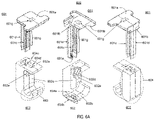
- FIGS. 6A and 6B illustrate three perspective views and two side views of sixth cable holder assembly 600 for placement between adjacent module frames 108 a and 108 b to facilitate a running for one or more electrical cables 102 / 104 within an array or grouping of solar modules.
- Cable holder assembly 600 may include plunger 601 and base 602 .
- Plunger 601 could include cap 601 a , stop 601 b , a leg component which includes inner vertical leg 601 c , outer vertical leg 601 d , intersecting vertical leg 601 e , and aperture 601 g .
- Cap 601 a includes lower surfaces 601 fa and 601 fb outward of stop 601 b .
- Stop 601 b extends away from cap 601 a in a substantially perpendicular direction and is designed for placement between module frames 108 a and 108 b .
- stop 601 b is configured to fictionally engage sides of module frames 108 a and 108 b when placed between module frames 108 a and 108 b.
- Inner vertical leg 601 c , outer vertical leg 601 d , and intersecting vertical leg 601 e form a generally H-shaped member extending away from cap 601 a in a substantially perpendicular direction.
- Inner and outer vertical legs 601 c and 601 d may run substantially parallel to one another and substantially perpendicular to vertical leg 601 e that extends in between inner and outer vertical legs 601 c and 601 d.
- a portion of an inner surface of inner vertical leg 601 c includes rack 601 g having teeth adapted to fall into notches or spaces formed by complementary teeth of pawl 602 d that form a ratchet when engaged with each other (not shown) for permitting motion or mobility of plunger 601 in only one direction.
- the teeth form a sawtooth surface having numerous diagonals surfaces between horizontal surfaces that are substantially parallel to cap 601 a to engage a complementary sawtooth surface of pawl 302 d.
- Base 602 could be defined with upper side 602 a having aperture 604 d , lower side 602 b , and inner side 602 c configured with pawl 602 d and receptacle 602 e .
- Pawl 602 d extends through receptacle 602 e and includes teeth adapted to fall into notches or spaces formed by complementary teeth of rack 601 g ;
- receptacle 602 e may have a size that is sufficient enough to facilitate an insertion of a plunger-disengagement tool for disengaging pawl 602 d from a complementary portion of rack 601 g when plunger 601 is extracted from base 602 .
- Pawl 602 d and a complementary portion of rack 601 g form a ratchet when engaged with each other (not shown) for permitting motion in only one direction, i.e., an insertion of plunger 601 into base 602 .
- an outward pulling force may be applied to pawl 602 d to move it away from rack 601 g and partially into aperture 604 d , allowing for extraction of plunger 601 from base 602 .
- Base 602 could include hook 603 and H-shaped receptacle 604 designed to accept an insertion of vertical legs 601 c , 601 d , and 601 e .
- Receptacle 604 is located outward of inner side 602 c and hook 603 .
- Receptacle 604 is defined by a substantially H-shaped cross-section and includes three openings 604 a , 604 b , and 604 c extending between and substantially perpendicular to upper side 602 a and lower side 602 b .
- a ridge e.g., ridge 302 f of FIG.
- plunger 601 When cable holder assembly 600 is placed between module frames 108 a and 108 b , plunger 601 is inserted into receptacle 604 while lower surfaces 601 fa and 601 fb of cap 601 a are placed above each upper surface 108 c of module frames 108 a and 108 b ; during the insertion, stop 601 b and upper side 602 a of base 602 are held in position between module frames 108 a and 108 b .
- pawl 602 d contacts complementary teeth of a portion of rack 601 g as rack 601 g begins to pass by until the insertion is stopped when hook 603 reaches its desired position to receive and support one or more electrical cables.
- FIGS. 7A and 7B illustrate three perspective views and two side views of seventh cable holder assembly 700 for placement between adjacent module frames 108 a and 108 b to facilitate a running for one or more electrical cables 102 / 104 within an array or grouping of solar modules.
- Cable holder assembly 700 may include plunger 701 and base 702 .
- Plunger 701 could include cap 701 a , stop 701 b , and a leg component which includes vertical leg 701 c .
- Cap 701 a includes lower surfaces 701 fa and 701 fb outward of stop 701 b .
- Stops 701 b extends away from cap 701 a in a substantially perpendicular direction and are designed for placement between module frames 108 a and 108 b .
- stop 701 b is configured to fictionally engage sides of module frames 108 a and 108 b when placed between module frames 108 a and 108 b.
- Vertical leg 701 c is located in between stop 701 b and extends away from lower surfaces 701 fa and 701 fb of cap 701 a in a substantially perpendicular direction.
- One surface of vertical leg 701 c includes rack 701 g having teeth adapted to fall into notches or spaces formed by complementary teeth of pawl 702 d that form a ratchet when engaged with each other (not shown) for permitting motion or mobility of plunger 701 in only one direction.
- the teeth form a sawtooth surface having numerous diagonals surfaces between horizontal surfaces that are substantially parallel to cap 701 a to engage a complementary sawtooth surface of pawl 702 d.
- Base 702 could be defined with upper side 702 a configured with ridge 702 f , lower side 402 b , and outer side 402 c .
- Base 702 could include hook 703 and tiered receptacle 704 having upper receptacle with an upper opening 704 e and a contiguous, lower receptacle with a lower opening 704 f .
- Receptacle 704 is located inward of outer side 702 c and outward of hook 703 .
- Lower opening 704 f is narrower than upper opening 704 e so that the lower receptacle accommodates an insertion of vertical leg 701 c
- upper opening 704 e is wider so that the upper receptacle accommodates not only an insertion of vertical leg 701 c but also an insertion of a plunger-disengagement tool between pawl 702 d and outer side 702 c for disengaging pawl 702 d from a complementary portion of rack 701 g when plunger 701 is extracted from base 702 .
- Pawl 702 d includes teeth adapted to fall into notches or spaces formed by complementary teeth of rack 701 g .
- Pawl 702 d and a complementary portion of rack 701 g form a ratchet when engaged with each other (not shown) for permitting motion in only one direction, i.e., an insertion of plunger 701 into base 702 .
- pawl 702 d includes tab 702 e to which a downward force may be applied from above to move pawl 702 d away from rack 701 g , allowing for a disengagement of pawl 702 d from a complementary portion of rack 701 g and an extraction of plunger 701 from base 702 .
- ridge 702 f and the teeth of pawl 702 d protrude upper receptacle as shown.
- plunger 701 When plunger 701 is inserted into base 702 , a pinching force is imparted on vertical leg 701 c between ridge 702 f and the teeth of pawl 702 d.
- plunger 701 When cable holder assembly 700 is placed between module frames 108 a and 108 b , plunger 701 is inserted into receptacle 704 while lower surfaces 701 fa and 701 fb of cap 701 a are placed above each upper surface 708 c of module frames 108 a and 108 b ; during the insertion, stop 701 b and upper side 702 a of base 702 are held in position between module frames 108 a and 108 b .
- pawl 702 d contacts complementary teeth of a portion of rack 701 g as rack 701 g begins to pass by until the insertion is stopped when hook 703 reaches its desired position to receive and support one or more electrical cables.
- FIG. 8 illustrates four perspective views of eighth cable holder assembly 800 for placement between adjacent module frames 108 a and 108 b to facilitate a running for one or more electrical cables 102 / 104 within an array or grouping of solar modules.
- Cable holder assembly 800 may include plunger 801 and base 802 .
- Plunger 801 could include cap 801 a , stops 801 ba and 801 bb , and a leg component which includes inner vertical leg 801 c , outer vertical leg 801 d , and intersecting vertical leg 801 e .
- Cap 801 a includes lower surfaces 801 fa and 801 fb in between stops 801 ba and 801 bb and inner vertical leg 801 c .
- Stops 801 ba and 801 bb extend away from cap 801 a in a substantially perpendicular direction and are designed for placement between module frames 108 a and 108 b .
- stops 801 ba and 801 bb are configured to fictionally engage sides of module frames 108 a and 108 b when placed between module frames 108 a and 108 b.
- Inner vertical leg 801 c , outer vertical leg 801 d , and intersecting vertical leg 801 e form a generally H-shaped member extending away from cap 801 a in a substantially perpendicular direction and substantially parallel to stops 801 ba and 801 bb .
- Inner and outer vertical legs 801 c and 801 d may run substantially parallel to one another and substantially perpendicular to vertical leg 801 e that extends in between inner and outer vertical legs 801 c and 801 d.
- an outer surface of outer vertical leg 801 d could include a rack (not shown) having teeth adapted to fall into notches or spaces formed by complementary teeth of a pawl (not shown) that form a ratchet when engaged with each other (not shown) for permitting motion or mobility of plunger 801 in only one direction.
- the teeth form a sawtooth surface having numerous diagonals surfaces between horizontal surfaces that are substantially parallel to cap 801 a to engage a complementary sawtooth surface of the pawl.
- base 802 could be defined with upper side 802 a , lower side 802 b , inner side 802 c , and an outer side (not shown).
- Base 802 could include hooks 803 a and 803 b (i.e., cable holders) and receptacle 804 located in between inner side 802 c and the outer side and designed to accept an insertion of vertical legs 801 b , 801 c , and 801 d ; it should be noted that, although not shown, receptacle 804 could be an H-shaped receptacle.
- Base 802 could be defined with upper side 802 a , lower side 802 b , and outer side 802 c .
- Base 802 could include hooks 803 a and 803 b , and receptacle 804 designed to accept an insertion of vertical legs 801 c , 801 d , and 801 e .
- Receptacle 804 is located inward of hooks 803 a and 803 b.
- plunger 801 When cable holder assembly 800 is placed between module frames 108 a and 108 b , plunger 801 is inserted into receptacle 804 while lower surfaces 801 fa and 801 fb of cap 801 a are placed above each upper surface 108 c of module frames 108 a and 108 b ; during the insertion, stops 801 ba and 801 bb and upper side 802 a of base 802 are held in position between module frames 108 a and 108 b .
- pawl 802 d contacts complementary teeth of a portion of rack 801 g as rack 801 g begins to pass by until the insertion is stopped when hook 803 reaches its desired position to receive and support one or more electrical cables.
- FIGS. 9A and 9B illustrates one perspective view and one side view, respectively, of solar component mounting system 900 in which a mount 910 may be coupled to solar module frame 108 of FIG. 1A to facilitate mounting of a solar component 902 affixed to an interface 904 (e.g., plate), where solar component 902 could be any component employed in an array or grouping of solar modules.
- solar component 902 could be a Module Level Power Electronics (MLPE), typically an optimizer or microinverter product in a smallish enclosure.
- MLPE Module Level Power Electronics
- FIGS. 9C through 9F illustrate one perspective view, one top view, and two side views, respectively, of mount 910 for facilitating the coupling of solar component 902 to solar module frame 108 .
- Mount 910 could include upper body 911 , lower body 912 , and/or fastener 913 .
- Upper body 911 includes rounded pivoting end 911 a , clamping end 911 b having clamping surface 911 c , and a threaded aperture through which a threaded portion of fastener 913 extends. Clamping end 911 b extends downwardly and substantially perpendicular to upper body 911 . Upper body 911 is designed to pivot around pivoting end 911 a and move in a counter-clockwise direction when a tightening force is applied to fastener 913 , drawing clamping surface 911 c to move downwardly towards lower body 912 .
- Lower body 912 includes rounded pivoting end enclosure 912 a , L-shaped member 912 b , clamp attachment member 912 c , and an aperture though which fastener 913 extends towards the treaded aperture of upper body 911 .
- Pivoting end enclosure 912 a is designed to provide an enclosure within which pivoting end 911 a may pivot.
- L-shaped member 912 b extends upwardly from lower body 912 b to form slot 912 d into which lower member 108 e of module frame 108 may be slid when mount 910 is coupled to module frame 108 .
- Clamp attachment member 912 c extends substantially radially away from pivoting end enclosure 912 a to provide a surface to which clip 912 e may be engaged. When engaged, clip 912 e may be used to secure cable(s) passing within the array or grouping of solar modules.
- Fastener 913 could include lock washer 913 a and spring 913 b .
- lock washer 913 a may include serrations that engage a lower surface of plate 904 .
- Spring 913 b may be employed to pre-load solar component 902 to plate 904 .
- plate 904 to which solar component 902 is affixed may be placed against lower body 912 and fastener 913 may be inserted through plate 904 (configured with an aperture or a slot through which fastener 913 may extend) and the aperture of lower body 912 to engage the aperture of upper body 911 .
- plate 904 is drawn towards lower body 912 until lock washer 913 a engages lower body 912 .
- lower member 108 e of module frame 108 may be slid into slot 912 d .
- clamping surface 911 c is drawn downwardly towards lower body 912 until the desired amount of clamping force is applied to lower body 912 by upper body 911 through clamping surface 911 c.
- FIGS. 10A and 10B illustrate one perspective view and one side view of a member formed into cable or wire hook 1000 as shown.
- the cable hook 1000 is formed so that a pair of outer portions comprised of first, second, and third segments may be placed on top sides of the module frames 108 enclosing solar panels 106 , as shown, while the middle of the cable hook 1000 forms a channel (e.g., a U-shape) that occupies a first plane and is placed between vertical sides of the adjacent module frames 108 using the pair of outer portions which occupy a second plane substantially perpendicular to the first plane and extending outward from ends of the channel.
- a channel e.g., a U-shape
- a first segment extends in the same plane as the channel and outward from an end of the channel until reaching a first turn. Then, a second segment turns at the first turn and extends in a first direction substantially perpendicular to the first segment until reaching a second turn. Then, a third segment turns at the second turn and extends is a second direction substantially opposite to the first direction until reaching an end of the member.
- the cable hook 1000 has been placed into a position to support one or more electrical cables and facilitate a running of the cable(s) between the vertical sides of the adjacent module frames 108 as shown.
- the second segments may turn in opposite directions (not shown).
- the term “embodiment” means an embodiment that serves to illustrate by way of example but not limitation. It should be understood that the aspects, features and advantages made apparent from the foregoing are efficiently attained and, since certain changes may be made in the disclosed inventive embodiments without departing from the spirit and scope of the invention, it is intended that all matter contained herein shall be interpreted as illustrative and not in a limiting sense.
Abstract
Description
Claims (12)
Priority Applications (3)
| Application Number | Priority Date | Filing Date | Title |
|---|---|---|---|
| US16/189,212 US11374532B2 (en) | 2017-11-13 | 2018-11-13 | Cable holder assemblies for a solar panel system |
| US17/391,709 US11848640B2 (en) | 2017-11-13 | 2021-08-02 | Cable holder assemblies for a solar panel system |
| US17/849,155 US11929708B2 (en) | 2017-11-13 | 2022-06-24 | Cable holder assemblies for a solar panel system |
Applications Claiming Priority (2)
| Application Number | Priority Date | Filing Date | Title |
|---|---|---|---|
| US201762585230P | 2017-11-13 | 2017-11-13 | |
| US16/189,212 US11374532B2 (en) | 2017-11-13 | 2018-11-13 | Cable holder assemblies for a solar panel system |
Related Child Applications (2)
| Application Number | Title | Priority Date | Filing Date |
|---|---|---|---|
| US17/391,709 Division US11848640B2 (en) | 2017-11-13 | 2021-08-02 | Cable holder assemblies for a solar panel system |
| US17/849,155 Continuation US11929708B2 (en) | 2017-11-13 | 2022-06-24 | Cable holder assemblies for a solar panel system |
Publications (2)
| Publication Number | Publication Date |
|---|---|
| US20190149087A1 US20190149087A1 (en) | 2019-05-16 |
| US11374532B2 true US11374532B2 (en) | 2022-06-28 |
Family
ID=66433682
Family Applications (3)
| Application Number | Title | Priority Date | Filing Date |
|---|---|---|---|
| US16/189,212 Active US11374532B2 (en) | 2017-11-13 | 2018-11-13 | Cable holder assemblies for a solar panel system |
| US17/391,709 Active US11848640B2 (en) | 2017-11-13 | 2021-08-02 | Cable holder assemblies for a solar panel system |
| US17/849,155 Active US11929708B2 (en) | 2017-11-13 | 2022-06-24 | Cable holder assemblies for a solar panel system |
Family Applications After (2)
| Application Number | Title | Priority Date | Filing Date |
|---|---|---|---|
| US17/391,709 Active US11848640B2 (en) | 2017-11-13 | 2021-08-02 | Cable holder assemblies for a solar panel system |
| US17/849,155 Active US11929708B2 (en) | 2017-11-13 | 2022-06-24 | Cable holder assemblies for a solar panel system |
Country Status (1)
| Country | Link |
|---|---|
| US (3) | US11374532B2 (en) |
Families Citing this family (5)
| Publication number | Priority date | Publication date | Assignee | Title |
|---|---|---|---|---|
| EP4186160A1 (en) * | 2020-07-23 | 2023-05-31 | The Board of Regents of the University of Oklahoma | Adaptor for spring-based pv module fastener |
| US11703152B2 (en) | 2020-10-22 | 2023-07-18 | Panduit Corp. | Wrap bracket with strap mount |
| US20220356963A1 (en) * | 2021-05-05 | 2022-11-10 | Shoals Technologies Group, Llc | Solar cable retention clips and systems for structure mounting |
| WO2022235675A1 (en) * | 2021-05-05 | 2022-11-10 | Shoals Technologies Group, Llc | Solar cable retention clips and systems |
| US11949217B1 (en) | 2022-09-19 | 2024-04-02 | EcoFasten Solar, LLC | Wire clamp |
Citations (23)
| Publication number | Priority date | Publication date | Assignee | Title |
|---|---|---|---|---|
| US3210030A (en) * | 1963-01-07 | 1965-10-05 | Gen Motors Corp | Wiring harness installation |
| US3494580A (en) * | 1967-09-13 | 1970-02-10 | Oswald Willy Thorsman | Cable clamp |
| US4118838A (en) * | 1976-04-14 | 1978-10-10 | Hilti Aktiengesellschaft | Pipe clamp |
| US4183120A (en) * | 1978-05-19 | 1980-01-15 | Thorne George W | Encircling devices |
| US4557455A (en) * | 1981-08-04 | 1985-12-10 | Schmelzer Corporation | Releasable and adjustable securing device |
| US4835933A (en) * | 1988-02-11 | 1989-06-06 | Yung Fernand P | Rebar spacer assembly |
| US5597280A (en) * | 1995-10-30 | 1997-01-28 | Yazaki Corporation | Locking clip with resilient barb arm |
| US5675128A (en) * | 1994-10-20 | 1997-10-07 | Simon; Hans | Cable terminal |
| US6126122A (en) * | 1997-11-06 | 2000-10-03 | Sioux Chief Manufacturing Co., Inc. | Double ratchet arm pipe clamp |
| US6463631B2 (en) * | 2000-05-17 | 2002-10-15 | Kitagawa Industries Co., Inc. | Binding tool |
| US20030218111A1 (en) * | 2002-05-23 | 2003-11-27 | Jean-Luc Labeirie | Device for fastening elongate objects onto a flat support |
| US6666425B1 (en) * | 2003-01-06 | 2003-12-23 | Jerry Lee Ferguson | Vertically-adjustable picture hangar |
| US6857608B2 (en) * | 2001-02-08 | 2005-02-22 | Emerald Innovations, Inc. | Adjustable wreath hanger |
| US20060131465A1 (en) * | 2004-12-22 | 2006-06-22 | Lynch Edward J Jr | Pipe support and method of installation |
| US7540451B2 (en) * | 2006-09-05 | 2009-06-02 | Se-Kure Controls, Inc. | System for securing a cable to a portable article |
| US20120037765A1 (en) * | 2010-08-10 | 2012-02-16 | Hans Peter Guthke | Device for holding systems and aircraft or spacecraft |
| US20120049011A1 (en) * | 2010-08-27 | 2012-03-01 | Hon Hai Precision Industry Co., Ltd. | Cable management apparatus |
| US20120097804A1 (en) * | 2010-10-21 | 2012-04-26 | Hon Hai Precision Industry Co., Ltd. | Cable management apparatus |
| US20120241583A1 (en) * | 2009-09-03 | 2012-09-27 | Brett Peter Potgieter | Picture hanger |
| US20150320242A1 (en) * | 2014-05-08 | 2015-11-12 | Brett Peter Potgieter | Picture hanger |
| US20170227141A1 (en) * | 2016-02-05 | 2017-08-10 | Hellermann Tyton Corporation | Adjustable p-clamp |
| US9915430B2 (en) * | 2007-03-26 | 2018-03-13 | Itw Industrial Components S.R.I. Con Unico Socio | Gas lighting device having simplified fastening means to an electric household appliance, in particular a cooking range |
| US20190036314A1 (en) * | 2016-02-05 | 2019-01-31 | Hellermanntyton Corporation | Adjustable p-clamp with multiple mounting options |
Family Cites Families (28)
| Publication number | Priority date | Publication date | Assignee | Title |
|---|---|---|---|---|
| US1877781A (en) * | 1931-02-13 | 1932-09-20 | Appleton Electric Co | Hanger |
| US2592791A (en) * | 1948-02-27 | 1952-04-15 | Dresser Equipment Company | Tubing clamp having opposite identical jaws |
| US2621353A (en) * | 1950-04-14 | 1952-12-16 | Stanley Home Products Inc | Mop holder having screw-operated clamping plate |
| US3026497A (en) * | 1957-08-22 | 1962-03-20 | Aluminum Co Of America | Center bolt connectors |
| US3228639A (en) * | 1963-05-02 | 1966-01-11 | Donald W Korns | Pipe clamp |
| DE1249372C2 (en) * | 1964-12-07 | 1968-03-21 | Fur Montage Technik Anstalt | Methods and devices for fastening cables, pipes and the like. Like. By means of one-piece or multi-part cable clamps |
| US3310901A (en) * | 1965-06-15 | 1967-03-28 | Sarkisian Robert | Display holder |
| US3721748A (en) * | 1972-05-05 | 1973-03-20 | Anderson Electric Corp | Device for upgrading the corona resistance of grounding studs |
| US3924920A (en) * | 1974-06-10 | 1975-12-09 | Western Electric Co | Device for clamping elongated member |
| US4597690A (en) * | 1979-11-23 | 1986-07-01 | Girard Development Incorporated | Tube clamps |
| US4597140A (en) * | 1983-08-08 | 1986-07-01 | Girard Development Incorporated | Tube clamp |
| US4764131A (en) * | 1987-07-13 | 1988-08-16 | Amp Incorporated | Electrical connector |
| US5930928A (en) * | 1997-09-05 | 1999-08-03 | Kantola; Thomas L. | Front-loading poster frame device |
| US7077855B2 (en) * | 1999-06-25 | 2006-07-18 | Curtis Patrick M | Pressure clamp for relieving a headache |
| DE202007008471U1 (en) * | 2007-06-13 | 2007-09-27 | Leichtmetallbau Schletter Gmbh | Device for connecting a rail to another component |
| DE202009007526U1 (en) * | 2009-05-27 | 2009-08-20 | Schletter Gmbh | Device for fastening a mounting rail to a threaded shaft |
| US8757560B2 (en) * | 2010-06-24 | 2014-06-24 | Wanaka Holdings, LLC | Cable retention device |
| US9450130B2 (en) * | 2011-01-27 | 2016-09-20 | Sunpower Corporation | Frame-mounted wire management device |
| US9873286B1 (en) * | 2012-02-14 | 2018-01-23 | Insignia Marketing, Inc. | Communication systems and kits |
| DE202012005714U1 (en) * | 2012-06-13 | 2013-09-16 | Schletter Gmbh | Holder for a profile rail |
| CN102777454B (en) * | 2012-06-28 | 2014-10-01 | 友达光电股份有限公司 | Solar device and fastening mechanism thereof |
| US9249813B2 (en) * | 2012-10-01 | 2016-02-02 | Technifab, Inc. | Clamp |
| CN103944503A (en) * | 2013-01-18 | 2014-07-23 | 台达电子工业股份有限公司 | Junction box bracket, junction box using junction box bracket and solar cell component |
| US10256765B2 (en) * | 2013-06-13 | 2019-04-09 | Building Materials Investment Corporation | Roof integrated photovoltaic system |
| US10396706B2 (en) * | 2014-02-25 | 2019-08-27 | John Powers, III | Flat roof solar sensor structures and clamp |
| US20160268965A1 (en) * | 2015-03-10 | 2016-09-15 | Vermont Slate & Copper Services, Inc. | Mounting bracket assmebly |
| US10312855B2 (en) * | 2016-05-31 | 2019-06-04 | Ironridge, Inc. | Bracket mount for securing micro-inverters and power optimizers to solar panel arrays |
| US10224870B2 (en) * | 2016-05-31 | 2019-03-05 | Ironridge, Inc. | Bracket mounting assembly for securing junction boxes to solar panel arrays |
-
2018
- 2018-11-13 US US16/189,212 patent/US11374532B2/en active Active
-
2021
- 2021-08-02 US US17/391,709 patent/US11848640B2/en active Active
-
2022
- 2022-06-24 US US17/849,155 patent/US11929708B2/en active Active
Patent Citations (23)
| Publication number | Priority date | Publication date | Assignee | Title |
|---|---|---|---|---|
| US3210030A (en) * | 1963-01-07 | 1965-10-05 | Gen Motors Corp | Wiring harness installation |
| US3494580A (en) * | 1967-09-13 | 1970-02-10 | Oswald Willy Thorsman | Cable clamp |
| US4118838A (en) * | 1976-04-14 | 1978-10-10 | Hilti Aktiengesellschaft | Pipe clamp |
| US4183120A (en) * | 1978-05-19 | 1980-01-15 | Thorne George W | Encircling devices |
| US4557455A (en) * | 1981-08-04 | 1985-12-10 | Schmelzer Corporation | Releasable and adjustable securing device |
| US4835933A (en) * | 1988-02-11 | 1989-06-06 | Yung Fernand P | Rebar spacer assembly |
| US5675128A (en) * | 1994-10-20 | 1997-10-07 | Simon; Hans | Cable terminal |
| US5597280A (en) * | 1995-10-30 | 1997-01-28 | Yazaki Corporation | Locking clip with resilient barb arm |
| US6126122A (en) * | 1997-11-06 | 2000-10-03 | Sioux Chief Manufacturing Co., Inc. | Double ratchet arm pipe clamp |
| US6463631B2 (en) * | 2000-05-17 | 2002-10-15 | Kitagawa Industries Co., Inc. | Binding tool |
| US6857608B2 (en) * | 2001-02-08 | 2005-02-22 | Emerald Innovations, Inc. | Adjustable wreath hanger |
| US20030218111A1 (en) * | 2002-05-23 | 2003-11-27 | Jean-Luc Labeirie | Device for fastening elongate objects onto a flat support |
| US6666425B1 (en) * | 2003-01-06 | 2003-12-23 | Jerry Lee Ferguson | Vertically-adjustable picture hangar |
| US20060131465A1 (en) * | 2004-12-22 | 2006-06-22 | Lynch Edward J Jr | Pipe support and method of installation |
| US7540451B2 (en) * | 2006-09-05 | 2009-06-02 | Se-Kure Controls, Inc. | System for securing a cable to a portable article |
| US9915430B2 (en) * | 2007-03-26 | 2018-03-13 | Itw Industrial Components S.R.I. Con Unico Socio | Gas lighting device having simplified fastening means to an electric household appliance, in particular a cooking range |
| US20120241583A1 (en) * | 2009-09-03 | 2012-09-27 | Brett Peter Potgieter | Picture hanger |
| US20120037765A1 (en) * | 2010-08-10 | 2012-02-16 | Hans Peter Guthke | Device for holding systems and aircraft or spacecraft |
| US20120049011A1 (en) * | 2010-08-27 | 2012-03-01 | Hon Hai Precision Industry Co., Ltd. | Cable management apparatus |
| US20120097804A1 (en) * | 2010-10-21 | 2012-04-26 | Hon Hai Precision Industry Co., Ltd. | Cable management apparatus |
| US20150320242A1 (en) * | 2014-05-08 | 2015-11-12 | Brett Peter Potgieter | Picture hanger |
| US20170227141A1 (en) * | 2016-02-05 | 2017-08-10 | Hellermann Tyton Corporation | Adjustable p-clamp |
| US20190036314A1 (en) * | 2016-02-05 | 2019-01-31 | Hellermanntyton Corporation | Adjustable p-clamp with multiple mounting options |
Also Published As
| Publication number | Publication date |
|---|---|
| US11848640B2 (en) | 2023-12-19 |
| US11929708B2 (en) | 2024-03-12 |
| US20210359643A1 (en) | 2021-11-18 |
| US20190149087A1 (en) | 2019-05-16 |
| US20230015441A1 (en) | 2023-01-19 |
Similar Documents
| Publication | Publication Date | Title |
|---|---|---|
| US11374532B2 (en) | Cable holder assemblies for a solar panel system | |
| US8727288B2 (en) | Snap-in bracket for attaching cabling to a support | |
| US9907208B2 (en) | Hold down for retaining a heat sink | |
| JP3086946U (en) | Memory heat dissipation device | |
| EP0855089B1 (en) | Solderable transistor clip and heat sink | |
| US6646881B1 (en) | Mounting assembly for heat sink | |
| KR101494941B1 (en) | Electronic apparatus and associated disassembly release tool | |
| US9549474B2 (en) | Cover removal fixture | |
| US9146062B2 (en) | Interlocking clip heatsink mounting system | |
| KR20150052063A (en) | Set top box having heat sink pressure applying means | |
| JP2014521224A (en) | Set-top box with snap-in heat sink and smart card reader with heat sink retention fastener | |
| US9456524B2 (en) | Robot controller enclosure | |
| CN104638582A (en) | Wire arranging device | |
| CN107710504B (en) | Vertically oriented electronic device, method of constructing and method of constructing a subassembly | |
| US10742007B2 (en) | Photovoltaic wire management system | |
| US20140263875A1 (en) | Wire management clip for structures such as solar racking systems | |
| US9717153B2 (en) | For retention base to fixture on cover removal fixture | |
| CN104180074A (en) | Cable clamp | |
| JP2006066736A (en) | Liquid-crystal television equipped with hook for tying cord | |
| US10290844B2 (en) | Retaining device for at least one battery cell | |
| US7881061B2 (en) | Mounting device for mounting heat sink onto electronic component | |
| US20140198447A1 (en) | Heat dissipation device for memory cards | |
| CN212485739U (en) | Wire converter | |
| CN101603545B (en) | Fan fixing frame and heat dissipation device using same | |
| KR100637696B1 (en) | Wire harness fix clip |
Legal Events
| Date | Code | Title | Description |
|---|---|---|---|
| FEPP | Fee payment procedure |
Free format text: ENTITY STATUS SET TO UNDISCOUNTED (ORIGINAL EVENT CODE: BIG.); ENTITY STATUS OF PATENT OWNER: LARGE ENTITY |
|
| AS | Assignment |
Owner name: SUNRUN SOUTH LLC, CALIFORNIA Free format text: ASSIGNMENT OF ASSIGNORS INTEREST;ASSIGNORS:MCPHEETERS, GREG;FIGURSKI, EMILY;FERGUSON, EZEKIEL;AND OTHERS;REEL/FRAME:047692/0475 Effective date: 20181129 |
|
| STPP | Information on status: patent application and granting procedure in general |
Free format text: APPLICATION DISPATCHED FROM PREEXAM, NOT YET DOCKETED |
|
| STPP | Information on status: patent application and granting procedure in general |
Free format text: DOCKETED NEW CASE - READY FOR EXAMINATION |
|
| STPP | Information on status: patent application and granting procedure in general |
Free format text: NON FINAL ACTION MAILED |
|
| STPP | Information on status: patent application and granting procedure in general |
Free format text: NON FINAL ACTION MAILED |
|
| STPP | Information on status: patent application and granting procedure in general |
Free format text: NON FINAL ACTION MAILED |
|
| STPP | Information on status: patent application and granting procedure in general |
Free format text: RESPONSE TO NON-FINAL OFFICE ACTION ENTERED AND FORWARDED TO EXAMINER |
|
| STPP | Information on status: patent application and granting procedure in general |
Free format text: NON FINAL ACTION MAILED |
|
| STPP | Information on status: patent application and granting procedure in general |
Free format text: ADVISORY ACTION MAILED |
|
| STPP | Information on status: patent application and granting procedure in general |
Free format text: DOCKETED NEW CASE - READY FOR EXAMINATION |
|
| STPP | Information on status: patent application and granting procedure in general |
Free format text: NON FINAL ACTION MAILED |
|
| STPP | Information on status: patent application and granting procedure in general |
Free format text: RESPONSE TO NON-FINAL OFFICE ACTION ENTERED AND FORWARDED TO EXAMINER |
|
| STPP | Information on status: patent application and granting procedure in general |
Free format text: FINAL REJECTION MAILED |
|
| STPP | Information on status: patent application and granting procedure in general |
Free format text: RESPONSE AFTER FINAL ACTION FORWARDED TO EXAMINER |
|
| STPP | Information on status: patent application and granting procedure in general |
Free format text: ADVISORY ACTION MAILED |
|
| STPP | Information on status: patent application and granting procedure in general |
Free format text: DOCKETED NEW CASE - READY FOR EXAMINATION |
|
| STPP | Information on status: patent application and granting procedure in general |
Free format text: NON FINAL ACTION MAILED |
|
| STPP | Information on status: patent application and granting procedure in general |
Free format text: RESPONSE TO NON-FINAL OFFICE ACTION ENTERED AND FORWARDED TO EXAMINER |
|
| STPP | Information on status: patent application and granting procedure in general |
Free format text: FINAL REJECTION MAILED |
|
| STPP | Information on status: patent application and granting procedure in general |
Free format text: NOTICE OF ALLOWANCE MAILED -- APPLICATION RECEIVED IN OFFICE OF PUBLICATIONS |
|
| STPP | Information on status: patent application and granting procedure in general |
Free format text: PUBLICATIONS -- ISSUE FEE PAYMENT VERIFIED |
|
| STCF | Information on status: patent grant |
Free format text: PATENTED CASE |