US11372187B2 - Non-metallic layer stranded optical cable with reversal point capable of being positioned and method for detecting the reversal point - Google Patents
Non-metallic layer stranded optical cable with reversal point capable of being positioned and method for detecting the reversal point Download PDFInfo
- Publication number
- US11372187B2 US11372187B2 US16/624,305 US201916624305A US11372187B2 US 11372187 B2 US11372187 B2 US 11372187B2 US 201916624305 A US201916624305 A US 201916624305A US 11372187 B2 US11372187 B2 US 11372187B2
- Authority
- US
- United States
- Prior art keywords
- cable core
- metal film
- reversal point
- definition image
- image recognizing
- Prior art date
- Legal status (The legal status is an assumption and is not a legal conclusion. Google has not performed a legal analysis and makes no representation as to the accuracy of the status listed.)
- Active, expires
Links
Images


Classifications
-
- G—PHYSICS
- G01—MEASURING; TESTING
- G01V—GEOPHYSICS; GRAVITATIONAL MEASUREMENTS; DETECTING MASSES OR OBJECTS; TAGS
- G01V3/00—Electric or magnetic prospecting or detecting; Measuring magnetic field characteristics of the earth, e.g. declination, deviation
- G01V3/08—Electric or magnetic prospecting or detecting; Measuring magnetic field characteristics of the earth, e.g. declination, deviation operating with magnetic or electric fields produced or modified by objects or geological structures or by detecting devices
-
- G02B6/447—
-
- G—PHYSICS
- G02—OPTICS
- G02B—OPTICAL ELEMENTS, SYSTEMS OR APPARATUS
- G02B6/00—Light guides; Structural details of arrangements comprising light guides and other optical elements, e.g. couplings
- G02B6/46—Processes or apparatus adapted for installing or repairing optical fibres or optical cables
- G02B6/56—Processes for repairing optical cables
- G02B6/562—Processes for repairing optical cables locatable, e.g. using magnetic means
-
- G—PHYSICS
- G01—MEASURING; TESTING
- G01R—MEASURING ELECTRIC VARIABLES; MEASURING MAGNETIC VARIABLES
- G01R33/00—Arrangements or instruments for measuring magnetic variables
- G01R33/02—Measuring direction or magnitude of magnetic fields or magnetic flux
-
- G—PHYSICS
- G01—MEASURING; TESTING
- G01R—MEASURING ELECTRIC VARIABLES; MEASURING MAGNETIC VARIABLES
- G01R33/00—Arrangements or instruments for measuring magnetic variables
- G01R33/02—Measuring direction or magnitude of magnetic fields or magnetic flux
- G01R33/04—Measuring direction or magnitude of magnetic fields or magnetic flux using the flux-gate principle
-
- G—PHYSICS
- G01—MEASURING; TESTING
- G01R—MEASURING ELECTRIC VARIABLES; MEASURING MAGNETIC VARIABLES
- G01R33/00—Arrangements or instruments for measuring magnetic variables
- G01R33/02—Measuring direction or magnitude of magnetic fields or magnetic flux
- G01R33/06—Measuring direction or magnitude of magnetic fields or magnetic flux using galvano-magnetic devices
- G01R33/07—Hall effect devices
-
- G—PHYSICS
- G01—MEASURING; TESTING
- G01R—MEASURING ELECTRIC VARIABLES; MEASURING MAGNETIC VARIABLES
- G01R33/00—Arrangements or instruments for measuring magnetic variables
- G01R33/02—Measuring direction or magnitude of magnetic fields or magnetic flux
- G01R33/06—Measuring direction or magnitude of magnetic fields or magnetic flux using galvano-magnetic devices
- G01R33/09—Magnetoresistive devices
- G01R33/093—Magnetoresistive devices using multilayer structures, e.g. giant magnetoresistance sensors
-
- G—PHYSICS
- G02—OPTICS
- G02B—OPTICAL ELEMENTS, SYSTEMS OR APPARATUS
- G02B6/00—Light guides; Structural details of arrangements comprising light guides and other optical elements, e.g. couplings
- G02B6/44—Mechanical structures for providing tensile strength and external protection for fibres, e.g. optical transmission cables
- G02B6/4479—Manufacturing methods of optical cables
- G02B6/4482—Code or colour marking
-
- H—ELECTRICITY
- H01—ELECTRIC ELEMENTS
- H01B—CABLES; CONDUCTORS; INSULATORS; SELECTION OF MATERIALS FOR THEIR CONDUCTIVE, INSULATING OR DIELECTRIC PROPERTIES
- H01B11/00—Communication cables or conductors
- H01B11/22—Cables including at least one electrical conductor together with optical fibres
-
- G—PHYSICS
- G01—MEASURING; TESTING
- G01R—MEASURING ELECTRIC VARIABLES; MEASURING MAGNETIC VARIABLES
- G01R15/00—Details of measuring arrangements of the types provided for in groups G01R17/00 - G01R29/00, G01R33/00 - G01R33/26 or G01R35/00
- G01R15/14—Adaptations providing voltage or current isolation, e.g. for high-voltage or high-current networks
- G01R15/20—Adaptations providing voltage or current isolation, e.g. for high-voltage or high-current networks using galvano-magnetic devices, e.g. Hall-effect devices, i.e. measuring a magnetic field via the interaction between a current and a magnetic field, e.g. magneto resistive or Hall effect devices
- G01R15/207—Constructional details independent of the type of device used
-
- G—PHYSICS
- G01—MEASURING; TESTING
- G01R—MEASURING ELECTRIC VARIABLES; MEASURING MAGNETIC VARIABLES
- G01R33/00—Arrangements or instruments for measuring magnetic variables
- G01R33/02—Measuring direction or magnitude of magnetic fields or magnetic flux
- G01R33/025—Compensating stray fields
-
- G—PHYSICS
- G01—MEASURING; TESTING
- G01R—MEASURING ELECTRIC VARIABLES; MEASURING MAGNETIC VARIABLES
- G01R33/00—Arrangements or instruments for measuring magnetic variables
- G01R33/02—Measuring direction or magnitude of magnetic fields or magnetic flux
- G01R33/028—Electrodynamic magnetometers
-
- G—PHYSICS
- G02—OPTICS
- G02B—OPTICAL ELEMENTS, SYSTEMS OR APPARATUS
- G02B6/00—Light guides; Structural details of arrangements comprising light guides and other optical elements, e.g. couplings
- G02B6/44—Mechanical structures for providing tensile strength and external protection for fibres, e.g. optical transmission cables
- G02B6/4479—Manufacturing methods of optical cables
- G02B6/449—Twisting
Definitions
- the present invention relates to a non-metallic layer stranded optical cable. More specifically, the present invention relates to a non-metallic layer stranded optical cable with a reversal point capable of being positioned and a method for detecting the reversal point.
- the non-metallic layer stranded optical cable is a round stranded cable core formed by a plurality of optical fiber-containing loose tubes twisted around a central reinforcing member.
- the non-metallic reinforcing member is located at the center of the optical cable, and the optical fiber-containing loose tubes are arranged around the reinforcing member.
- SZ stranding technology is used in making the non-metallic layer stranded optical cable.
- a SZ layer stranded optical cable can meet such requirements, but the reversal point of SZ stranding should be determined, which makes it difficult and inefficient for drawing out an optical fiber.
- the objective of the present invention is to provide a non-metallic layer stranded optical cable with a reversal point capable of being positioned, so that the reversal point of a cable core can be determined, which facilitates an operation of drawing out an optical fiber from the optical cable.
- a non-metallic layer stranded optical cable with a reversal point capable of being positioned includes a cable core and a metal film provided at each reversal point of the cable core, and an outer sheath is provided outside the cable core.
- the metal film is provided at each reversal point of the cable core, allowing each reversal point of the cable core to have the metal film, and the cable core is wrapped by the outer sheath.
- a metal detector is used to move along the cable core until the metal film is detected by the metal detector. That is, the reversal point of the cable core is found which facilitates the operation of drawing out the optical fiber from the optical cable.
- the metal film is formed by spraying a metallic paint on an outer wall of the cable core, or the metal film is attached to the outer wall of the cable core.
- attaching and spraying are relatively simple construction methods thereby facilitating an operation of providing the metal film at the reversal point.
- Another objective of the present invention is to provide a method for detecting the reversal point of the above non-metallic layer stranded optical cable with the reversal point capable of being positioned, including the following steps: when an operation of drawing out an optical fiber from the optical cable is performed, detecting a position of the metal film in the optical cable by a metal detector. After turning on the power of the metal detector, a metal detection is carried out. While holding a hand grip and detecting and scanning around the optical cable to be detected by a detecting surface and moving to a position of the metal film, the metal detector emits an alarm sound or vibration, and the position is determined to be the reversal point of the optical cable.
- the position of the metal film is detected by the metal detector, which facilitates the operation. After the position of the metal film is detected, the outer sheath is cut to perform the operation of drawing out the optical fiber from the optical cable.
- Another objective of the present invention is to provide a method for manufacturing a cable core of the above non-metallic layer stranded optical cable with the reversal point capable of being positioned, including the following steps.
- Step 1 Gradually releasing a reinforcing member and a loose tube by a reinforcing member pay-out stand and a loose tube pay-out stand. Entering an SZ stranding platform through a strand collecting frame, and then entering a bundling machine after outputting from the SZ stranding platform to form the cable core.
- Step 2 Preparing a reversal point sample of the cable core with the specification to be manufactured and putting an image of the reversal point sample into a high-definition image recognizing device as a reference standard for identifying the reversal point of the cable core by the device.
- a signal is sent to the length measuring device.
- the length measuring device receives a trigger signal from the high-definition image recognizing device, a length of the cable core is started to be measured.
- a measured value is equal to the predetermined value L1
- a signal is sent to the marking device of the metal film, and the device returns to zero and waits for a next trigger signal.
- the marking device of the metal film When the marking device of the metal film receives a signal from the length measuring device, the metal film is immediately attached or a metal liquid is instantly sprayed on the cable core at the point B to mark the reversal point of the cable core and in this way, all reversal points of SZ stranding on the cable core are marked.
- Step 3 Collecting the cable core from the length measuring device by a wire take-up machine.
- the cable core is identified by the high-definition image recognition device, facilitating to find out the position of the reversal point on the cable core.
- the marking device of the metal film facilitates the operation of providing the metal film onto the cable core. After the marking device of the metal film marks the reversal point of the cable core, the cable core is collected by the wire take-up machine, which realizes the mass-production of the mark at the reversal point.
- a gap between the high-definition image recognizing device and the marking device of the metal film is greater than 300 mm and less than a spacing between adjacent two reversal points.
- the gap between the high-definition image recognizing device and the marking device of the metal film is less than the spacing between the adjacent two reversal points, which reduces the possibility of failing to mark the reversal point that is supposed to be marked.
- the marking device of the metal film is a labeling machine or a spraying robot.
- the metal film is attached onto the cable core by the labeling machine, and the spraying robot sprays the metal liquid on the reversal point of the cable core when the cable core passes.
- the high-definition image recognizing device includes an image inputting module configured for acquiring information of the reversal point sample of the cable core, an image information acquiring unit configured for acquiring information of the reversal point of the cable core, and a comparing module configured for comparing the information of the reversal point sample of the cable core with the acquired information of the reversal point of the cable core, and if the acquired information is consistent with the information of the reversal point sample, determining the reversal point of the cable core, and sending a signal to the length measuring device.
- an image inputting module configured for acquiring information of the reversal point sample of the cable core
- an image information acquiring unit configured for acquiring information of the reversal point of the cable core
- a comparing module configured for comparing the information of the reversal point sample of the cable core with the acquired information of the reversal point of the cable core, and if the acquired information is consistent with the information of the reversal point sample, determining the
- the high-definition image recognizing device collects the reversal point sample of the cable core as a sample through the image inputting module.
- the image information acquiring unit collects the reversal point of the cable core.
- the comparing module identifies the reversal point of the cable core, and sends information to the length measuring device.
- the length measuring device sends a signal to the marking device of the metal film, which facilitates the operation at the reversal point of the cable core by the marking device of the metal film.
- the spraying robot includes a spray gun and a connecting rod extending downward provided on the spray gun.
- a storage box opposite to a muzzle of the spray gun is provided at one end of the connecting rod away from the spray gun.
- the setting of the storage box makes allows the surrounding metal liquid to be collected when the reversal point of the cable core is sprayed by the spray gun, thereby improving the cleanliness of the working environment for the spraying robot.
- a moving member is respectively provided at lower ends of the high-definition image recognizing device and the marking device of the metal film to make the high-definition image recognizing device and the marking device of the metal film move.
- the setting of the moving member facilitates an adjustment of a distance between the high-definition image recognizing device and the marking device of the metal film, thereby facilitating the processing of different types of reversal points of the cable core.
- the moving member includes a moving plate provided at the lower end of the high-definition image recognizing device or the marking device of the metal film.
- Rollers are provided at a lower end of the moving plate.
- a plurality of vertical supporting columns and the moving plate are in a threaded connection, and a length of each of the supporting columns is greater than a height of each of the rollers.
- a marking plate with a scale is provided on one of the moving plates. The marking plate extends toward the other moving plate.
- An indicating plate is provided on the other moving plate through which the marking plate passes.
- the supporting columns are rotated away from the ground, so that the rollers are in contact with the ground, thereby facilitating to move the high-definition image recognizing device or the marking device of the metal film.
- the settings of the marking plate and the indicating plate enable the high-definition image recognizing device or the marking device of the metal film to move in a straight line while moving, and the presence of the marking plate can realize a precise adjustment of the distance between the high-definition image recognizing device and the marking device of the metal film, so that the high definition image recognizing device and the marking device of the metal film are adjusted according to the distance between adjacent reversal points on the cable core.
- the present invention has the advantages of the metal film is provided at each reversal point of the cable core, allowing each reversal point of the cable core to have the metal film, and the cable core is wrapped by the outer sheath.
- a metal detector is used to move along the cable core until the metal film is detected by the metal detector. That is, the reversal point of the cable core is found which facilitates the operation of drawing the optical fiber from the optical cable.
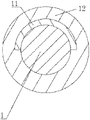
- FIG. 1 is a structural schematic diagram according to embodiment 1;
- FIG. 2 is a structural schematic diagram of embodiment 1 showing an outer sheath
- FIG. 3 is a flow chart of a manufacturing method according to embodiment 3;
- FIG. 4 is a diagram of devices for manufacturing a cable core according to embodiment 3.
- FIG. 5 is a structural schematic diagram of a high-definition image recognizing device according to embodiment 3.
- FIG. 6 is a structural schematic diagram of a moving member according to embodiment 3.
- FIG. 7 is a structural schematic diagram of a marking plate according to embodiment 3.
- 1 cable core
- 11 metal film
- 12 outer sheath
- 2 refinforcing member pay-out stand
- 3 loose tube pay-out stand
- 4 strand collecting frame
- 5 SZ stranding platform
- 7 high-definition image recognizing device
- 71 tractor
- 8 marking device of a metal film
- 81 two-wheel tension regulating device
- 82 spray gun
- 83 connecting rod
- 84 storage box
- 85 moving plate
- 86 roller
- 87 supporting column
- 88 marking plate
- 89 indicating plate
- 9 length measuring device
- 91 wire take-up machine.
- a non-metallic layer stranded optical cable with a reversal point capable of being positioned is provided, as shown in FIG. 1 and FIG. 2 , whose cable core 1 is manufactured by SZ stranding technology.
- the non-metallic layer stranded optical cable with the reversal point capable of being positioned includes the cable core 1 and the metal film 11 provided at each reversal point of the cable core 1 .
- the metal film 11 is provided at one side of the cable core 1 , or may be wrapped on an outer side of the cable core 1 , but is not limited thereto.
- the outer sheath 12 is provided outside the cable core 1 .
- a metal detector is used to move along the cable core 1 until the metal film 11 is detected by the metal detector. That is, the reversal point of the cable core 1 is found, which facilitates an operation of drawing an optical fiber from the optical cable, eases the construction and effectively improves the construction efficiency.
- the metal film 11 is formed by spraying a metallic paint on an outer wall of the cable core 1 .
- the metal film 11 is attached to the outer wall of the cable core 1 , and a bonding layer is provided on one side of the metal film 11 facing the cable core 1 .
- the metal film 11 can be quickly and easily applied to the reversal point of the cable core 1 by the above two methods.
- the construction method of the metal film 11 in the present invention is not limited to the above two methods.
- a method for detecting the reversal point of the non-metallic layer stranded optical cable with the reversal point capable of being positioned in embodiment 1 includes the following steps.
- a position of the metal film 11 in the optical cable is detected by the metal detector.
- a metal detection can be performed.
- the metal detector While holding a hand grip and detecting and scanning around the optical cable to be detected by a detecting surface and reaching the position of the metal film 11 , the metal detector emits an alarm sound or vibration, and this position is the reversal point of the optical cable.
- the outer sheath 12 is cut to perform the operation of drawing out the optical fiber from the optical cable, which facilitates the operation.
- a method for manufacturing the non-metallic layer stranded optical cable with the reversal point capable of being positioned in embodiment 1 is provided, as shown in FIG. 3 and FIG. 4 ,
- Step 1 The reinforcing member and the loose tube are gradually released by the reinforcing member pay-out stand 2 and the loose tube pay-out stand 3 . Enter the SZ stranding platform 5 through the strand collecting frame 4 , and then enter the bundling machine 6 after outputting from the SZ stranding platform 5 to form the cable core 1 .
- Step 2 A reversal point sample of the cable core 1 with the specification to be manufactured is prepared, and an image of the reversal point sample is input into the high-definition image recognizing device 7 as a reference standard for identifying the reversal point of the cable core 1 by the device.
- An installation point of the high-definition image recognizing device 7 is referred to as “point A”.
- An installation point of the marking device of the metal film 11 is referred to as “point B” and a length of the cable core 1 from the point A to the point B is measured and recorded as “L1”.
- the cable core 1 passes through the high-definition image recognizing device 7 and enters the marking device of the metal film 11 through the tractor 71 .
- the cable core 1 from the marking device of the metal film 11 enters the length measuring device 9 through the two-wheel tension regulating device 81 .
- a signal is sent to the length measuring device 9 .
- the length measuring device 9 After receiving a trigger signal from the high-definition image recognizing device 7 , the length measuring device 9 starts to measure a length of the cable core 1 .
- a measured value is equal to the predetermined value L1
- a signal is sent to the marking device of the metal film 11 , and the device returns to zero, waiting for a next trigger signal.
- the marking device of the metal film 11 When the marking device of the metal film 11 receives a signal from the length measuring device 9 , a metal film is immediately attached or a metal liquid is instantly sprayed onto the cable core 1 at the point B to mark the reversal point of the cable core 1 . In this way, all reversal points of SZ stranding in the cable core 1 are marked, which realizes the mass-production of the mark at the reversal point.
- Step 3 The cable core 1 from the length measuring device 9 is then collected by the wire take-up machine 91 .
- a gap between the high-definition image recognizing device 7 and the marking device of the metal film 11 is greater than 300 mm, and is less than a spacing between two adjacent reversal points, which reduces the possibility of failing to mark the reversal point that is supposed to be marked.
- the marking device of the metal film 11 is a labeling machine or a spraying robot.
- the model of the spraying robot may be an RDPT01 spraying robot.
- the metal film 11 is attached onto the cable core 1 by the labeling machine.
- the spraying robot sprays the metal liquid on the reversal point of the cable core 1 when the cable core 1 passes.
- the high-definition image recognizing device 7 includes an image inputting module configured for acquiring information of a reversal point sample of the cable core 1 , an image information acquiring unit configured for acquiring information of a reversal point of the cable core 1 , and a comparing module configured for comparing the information of the reversal point sample of the cable core 1 with the acquired information of the reversal point of the cable core 1 , and if the acquired information is consistent with the information of the reversal point sample, the reversal point of the cable core 1 is determined, and a signal is sent to the length measuring device 9 .
- the high-definition image recognizing device 7 collects the reversal point sample of the cable core 1 as a sample through the image inputting module.
- the image information acquiring unit collects the reversal point of the cable core 1 .
- the comparing module identifies the reversal point of the cable core 1 , and sends the information to the length measuring device 9 .
- the length measuring device 9 sends a signal to the marking device of the metal film 11 , which facilitates the construction at the reversal point of the cable core 1 by the marking device of the metal film 11 .
- the spraying robot includes the spray gun 82 and the connecting rod 83 extending downward provided on the spray gun 82 .
- the storage box 84 opposite to a muzzle of the spray gun 82 is provided at one end of the connecting rod 83 away from the spray gun 82 .
- the setting of the storage box 84 allows the surrounding metal liquid to be collected when the reversal point of the cable core 1 is sprayed by the spray gun 82 , thereby improving the cleanliness of the working environment for the spraying robot.
- a moving member is respectively provided at lower ends of the high-definition image recognizing device 7 and the marking device of the metal film 11 to make the high-definition image recognizing device 7 and the marking device of the metal film 11 move.
- the setting of the moving member facilitates adjusting the distance between the high-definition image recognizing device 7 and the marking device of the metal film 11 , thereby facilitating the processing of the different types of the reversal points of the cable core 1 .
- the moving member includes the moving plate 85 provided at the lower end of the high-definition image recognizing device 7 or the marking device of the metal film 11 .
- Rollers 86 are provided at a lower end of the moving plate 85 .
- the number of the rollers 86 can be four, and the rollers 86 are distributed at four corners of the moving plate 85 .
- a plurality of vertical supporting columns 87 and the moving plate 85 are in a threaded connection, and the length of each of the supporting columns 87 is greater than the height of each of the rollers 86 .
- the supporting columns 87 are rotated away from the ground, so that the rollers 86 are in contact with the ground, thereby facilitating to move the high-definition image recognizing device 7 or the marking device of the metal film 11 .
- the supporting columns 87 are rotated downward until the supporting columns 87 are in contact with the ground and the rollers 86 are lifted off the ground.
- the marking plate 88 with the scale is provided on one of the moving plates 85 .
- the marking plate 88 extends toward the other moving plate 85 .
- the indicating plate 89 is provided on the other moving plate 85 through which the marking plate 88 passes.
- the settings of the marking plate 88 and the indicating plate 89 enable the high-definition image recognizing device 7 or the marking device of the metal film 11 to move in a straight line while moving, and the presence of the marking plate 88 can realize a precise adjustment of the distance between the high-definition image recognizing device 7 and the marking device of the metal film 11 , so that the high definition image recognizing device 7 and the marking device of the metal film 11 are adjusted according to the distance between adjacent reversal points on the cable core 1 .
Landscapes
- Physics & Mathematics (AREA)
- General Physics & Mathematics (AREA)
- Engineering & Computer Science (AREA)
- Condensed Matter Physics & Semiconductors (AREA)
- Remote Sensing (AREA)
- Life Sciences & Earth Sciences (AREA)
- Optics & Photonics (AREA)
- Electromagnetism (AREA)
- Manufacturing & Machinery (AREA)
- Environmental & Geological Engineering (AREA)
- Geology (AREA)
- General Life Sciences & Earth Sciences (AREA)
- Geophysics (AREA)
- Length Measuring Devices By Optical Means (AREA)
Abstract
Description
Claims (8)
Applications Claiming Priority (1)
| Application Number | Priority Date | Filing Date | Title |
|---|---|---|---|
| PCT/CN2019/070330 WO2020140246A1 (en) | 2019-01-04 | 2019-01-04 | Non-metallic layer twisted reversal point positioning optical cable and detection method therefor |
Publications (2)
| Publication Number | Publication Date |
|---|---|
| US20210231894A1 US20210231894A1 (en) | 2021-07-29 |
| US11372187B2 true US11372187B2 (en) | 2022-06-28 |
Family
ID=71406651
Family Applications (1)
| Application Number | Title | Priority Date | Filing Date |
|---|---|---|---|
| US16/624,305 Active 2039-12-13 US11372187B2 (en) | 2019-01-04 | 2019-01-04 | Non-metallic layer stranded optical cable with reversal point capable of being positioned and method for detecting the reversal point |
Country Status (2)
| Country | Link |
|---|---|
| US (1) | US11372187B2 (en) |
| WO (1) | WO2020140246A1 (en) |
Citations (14)
| Publication number | Priority date | Publication date | Assignee | Title |
|---|---|---|---|---|
| US20020009282A1 (en) * | 1997-06-12 | 2002-01-24 | Grulick Matthew J. | Fiber optic cable marking process and a sensor device for use therewith |
| US20030002830A1 (en) * | 2001-06-27 | 2003-01-02 | Michael Petryszak | Method of determining lay length of S-Z stranded buffer tubes in optical fiber cable during manufacturing |
| JP2008058219A (en) | 2006-09-01 | 2008-03-13 | Toshiba Corp | Buried object exploration equipment |
| CN201233759Y (en) | 2008-08-01 | 2009-05-06 | 江苏通光信息有限公司 | Identifiable submarine cable with intelligent electronic tag |
| US20100278494A1 (en) * | 2009-04-30 | 2010-11-04 | Foertsch Johann | Optical Cable and Arrangement for Producing an Optical Cable |
| CN103715589A (en) | 2014-01-23 | 2014-04-09 | 刘光辉 | Core wire color separation positioning device for multi-core wires and cables |
| US20140112630A1 (en) * | 2012-10-23 | 2014-04-24 | Draka Comteq B.V. | Optical Fiber Cable |
| JP2016057366A (en) | 2014-09-05 | 2016-04-21 | 株式会社フジクラ | Manufacturing method of optical fiber cable |
| CN105700091A (en) | 2016-04-14 | 2016-06-22 | 杭州富通通信技术股份有限公司 | Optical cable |
| CN205665442U (en) | 2016-05-16 | 2016-10-26 | 西安西古光通信有限公司 | Layer -stranding cable's integrative apparatus for producing of stranding sheath |
| US20170131496A1 (en) * | 2012-09-26 | 2017-05-11 | Corning Optical Communications LLC | Binder film for a fiber optic cable |
| CN206546441U (en) | 2017-03-13 | 2017-10-10 | 河北九华勘查测绘有限责任公司 | A kind of pre-buried branch detection device of buried metal pipeline |
| CN107765313A (en) | 2017-11-22 | 2018-03-06 | 苏州川鹏塑料有限公司 | Equipment for moulding product metal insert mistake proofing detection |
| CN107870402A (en) | 2017-11-30 | 2018-04-03 | 长飞光纤光缆股份有限公司 | Loose-sleeve layer stranded optical cable and cabling device and cabling process thereof |
-
2019
- 2019-01-04 US US16/624,305 patent/US11372187B2/en active Active
- 2019-01-04 WO PCT/CN2019/070330 patent/WO2020140246A1/en not_active Ceased
Patent Citations (14)
| Publication number | Priority date | Publication date | Assignee | Title |
|---|---|---|---|---|
| US20020009282A1 (en) * | 1997-06-12 | 2002-01-24 | Grulick Matthew J. | Fiber optic cable marking process and a sensor device for use therewith |
| US20030002830A1 (en) * | 2001-06-27 | 2003-01-02 | Michael Petryszak | Method of determining lay length of S-Z stranded buffer tubes in optical fiber cable during manufacturing |
| JP2008058219A (en) | 2006-09-01 | 2008-03-13 | Toshiba Corp | Buried object exploration equipment |
| CN201233759Y (en) | 2008-08-01 | 2009-05-06 | 江苏通光信息有限公司 | Identifiable submarine cable with intelligent electronic tag |
| US20100278494A1 (en) * | 2009-04-30 | 2010-11-04 | Foertsch Johann | Optical Cable and Arrangement for Producing an Optical Cable |
| US20170131496A1 (en) * | 2012-09-26 | 2017-05-11 | Corning Optical Communications LLC | Binder film for a fiber optic cable |
| US20140112630A1 (en) * | 2012-10-23 | 2014-04-24 | Draka Comteq B.V. | Optical Fiber Cable |
| CN103715589A (en) | 2014-01-23 | 2014-04-09 | 刘光辉 | Core wire color separation positioning device for multi-core wires and cables |
| JP2016057366A (en) | 2014-09-05 | 2016-04-21 | 株式会社フジクラ | Manufacturing method of optical fiber cable |
| CN105700091A (en) | 2016-04-14 | 2016-06-22 | 杭州富通通信技术股份有限公司 | Optical cable |
| CN205665442U (en) | 2016-05-16 | 2016-10-26 | 西安西古光通信有限公司 | Layer -stranding cable's integrative apparatus for producing of stranding sheath |
| CN206546441U (en) | 2017-03-13 | 2017-10-10 | 河北九华勘查测绘有限责任公司 | A kind of pre-buried branch detection device of buried metal pipeline |
| CN107765313A (en) | 2017-11-22 | 2018-03-06 | 苏州川鹏塑料有限公司 | Equipment for moulding product metal insert mistake proofing detection |
| CN107870402A (en) | 2017-11-30 | 2018-04-03 | 长飞光纤光缆股份有限公司 | Loose-sleeve layer stranded optical cable and cabling device and cabling process thereof |
Non-Patent Citations (1)
| Title |
|---|
| CN 105700091 Machine Translation, Jun. 22, 2016 (Year: 2016). * |
Also Published As
| Publication number | Publication date |
|---|---|
| US20210231894A1 (en) | 2021-07-29 |
| WO2020140246A1 (en) | 2020-07-09 |
Similar Documents
| Publication | Publication Date | Title |
|---|---|---|
| CN205209928U (en) | On --spot detection device of aviation spraying droplet deposition | |
| CN114194937B (en) | A method for monitoring the winding quality of high-speed winding machines | |
| US20220291468A1 (en) | System and method of controlling a strander by wireless visual monitoring of a subunit reel | |
| DE60214286D1 (en) | Method for determining the impact length of SZ-stranded protective tubes in fiber optic cables during manufacture | |
| CN206379220U (en) | A kind of cable-former with fault detection capability | |
| US11372187B2 (en) | Non-metallic layer stranded optical cable with reversal point capable of being positioned and method for detecting the reversal point | |
| CN114508646B (en) | Intelligent detection method and system for overhauling pipeline by utilizing pipeline robot | |
| CN206339721U (en) | A kind of aluminium strip wraps up production line with optical cable | |
| CN112815840A (en) | General cable strand linear measuring method of suspension bridge based on machine vision | |
| CN108768511A (en) | A kind of intelligent selecting method and device of two dimension MEMS OSW photoswitches Hitless points | |
| EP3730931A1 (en) | Image detection system | |
| CN205384229U (en) | Cable jacket defect intelligence processing system | |
| CN104535220A (en) | Electric power aerial optical cable distributive on-line monitoring device | |
| JP6106144B2 (en) | Optical fiber test apparatus and optical fiber test system | |
| CN108548514B (en) | Optical fiber surplus length dynamic measurement system for steel pipe production line | |
| CN110631752A (en) | Optical cable stranding and yarn binding tension on-line monitoring device and method | |
| KR100334793B1 (en) | Vibration monitoring apparatus for optic fiber drawing equipment and method thereof | |
| CN209945304U (en) | Online testing system for extra length of optical fiber of beam tube | |
| US20190339160A1 (en) | Inspection device of optical fiber unit and method of manufacturing optical fiber unit | |
| CN110728672A (en) | A measuring method for type identification of concentric strand structure of round wire | |
| CN118328982A (en) | Inclinometer traction robot and inclinometer method using the same | |
| JP2000324639A (en) | Monitoring method of overhead wire sag | |
| CN108821037A (en) | A kind of Electromagnetic CT data collection system | |
| CN214066402U (en) | Real-time on-line measurement yarn-releasing tension device | |
| CN210154526U (en) | On-line excess length monitoring device for optical fiber composite overhead ground wire |
Legal Events
| Date | Code | Title | Description |
|---|---|---|---|
| AS | Assignment |
Owner name: NANJING WASIN FUJIKURA OPTICAL COMMUNICATION LTD., CHINA Free format text: ASSIGNMENT OF ASSIGNORS INTEREST;ASSIGNORS:YAO, QIANG;YIN, PENG XIANG;REEL/FRAME:051370/0226 Effective date: 20191206 |
|
| FEPP | Fee payment procedure |
Free format text: ENTITY STATUS SET TO UNDISCOUNTED (ORIGINAL EVENT CODE: BIG.); ENTITY STATUS OF PATENT OWNER: SMALL ENTITY |
|
| FEPP | Fee payment procedure |
Free format text: ENTITY STATUS SET TO SMALL (ORIGINAL EVENT CODE: SMAL); ENTITY STATUS OF PATENT OWNER: SMALL ENTITY |
|
| STPP | Information on status: patent application and granting procedure in general |
Free format text: APPLICATION DISPATCHED FROM PREEXAM, NOT YET DOCKETED |
|
| STPP | Information on status: patent application and granting procedure in general |
Free format text: DOCKETED NEW CASE - READY FOR EXAMINATION |
|
| STPP | Information on status: patent application and granting procedure in general |
Free format text: NON FINAL ACTION MAILED |
|
| STPP | Information on status: patent application and granting procedure in general |
Free format text: RESPONSE TO NON-FINAL OFFICE ACTION ENTERED AND FORWARDED TO EXAMINER |
|
| STPP | Information on status: patent application and granting procedure in general |
Free format text: PUBLICATIONS -- ISSUE FEE PAYMENT RECEIVED |
|
| STPP | Information on status: patent application and granting procedure in general |
Free format text: PUBLICATIONS -- ISSUE FEE PAYMENT VERIFIED |
|
| STCF | Information on status: patent grant |
Free format text: PATENTED CASE |
|
| MAFP | Maintenance fee payment |
Free format text: PAYMENT OF MAINTENANCE FEE, 4TH YR, SMALL ENTITY (ORIGINAL EVENT CODE: M2551); ENTITY STATUS OF PATENT OWNER: SMALL ENTITY Year of fee payment: 4 |