US11370052B2 - Arc welding system and wire feeding device - Google Patents
Arc welding system and wire feeding device Download PDFInfo
- Publication number
- US11370052B2 US11370052B2 US16/080,251 US201716080251A US11370052B2 US 11370052 B2 US11370052 B2 US 11370052B2 US 201716080251 A US201716080251 A US 201716080251A US 11370052 B2 US11370052 B2 US 11370052B2
- Authority
- US
- United States
- Prior art keywords
- welding
- wire
- power supply
- welding wire
- current
- Prior art date
- Legal status (The legal status is an assumption and is not a legal conclusion. Google has not performed a legal analysis and makes no representation as to the accuracy of the status listed.)
- Active, expires
Links
Images


Classifications
-
- B—PERFORMING OPERATIONS; TRANSPORTING
- B23—MACHINE TOOLS; METAL-WORKING NOT OTHERWISE PROVIDED FOR
- B23K—SOLDERING OR UNSOLDERING; WELDING; CLADDING OR PLATING BY SOLDERING OR WELDING; CUTTING BY APPLYING HEAT LOCALLY, e.g. FLAME CUTTING; WORKING BY LASER BEAM
- B23K9/00—Arc welding or cutting
- B23K9/12—Automatic feeding or moving of electrodes or work for spot or seam welding or cutting
- B23K9/133—Means for feeding electrodes, e.g. drums, rolls, motors
-
- B—PERFORMING OPERATIONS; TRANSPORTING
- B23—MACHINE TOOLS; METAL-WORKING NOT OTHERWISE PROVIDED FOR
- B23K—SOLDERING OR UNSOLDERING; WELDING; CLADDING OR PLATING BY SOLDERING OR WELDING; CUTTING BY APPLYING HEAT LOCALLY, e.g. FLAME CUTTING; WORKING BY LASER BEAM
- B23K9/00—Arc welding or cutting
- B23K9/12—Automatic feeding or moving of electrodes or work for spot or seam welding or cutting
- B23K9/124—Circuits or methods for feeding welding wire
-
- B—PERFORMING OPERATIONS; TRANSPORTING
- B23—MACHINE TOOLS; METAL-WORKING NOT OTHERWISE PROVIDED FOR
- B23K—SOLDERING OR UNSOLDERING; WELDING; CLADDING OR PLATING BY SOLDERING OR WELDING; CUTTING BY APPLYING HEAT LOCALLY, e.g. FLAME CUTTING; WORKING BY LASER BEAM
- B23K9/00—Arc welding or cutting
- B23K9/06—Arrangements or circuits for starting the arc, e.g. by generating ignition voltage, or for stabilising the arc
- B23K9/073—Stabilising the arc
- B23K9/0732—Stabilising of the arc current
-
- B—PERFORMING OPERATIONS; TRANSPORTING
- B23—MACHINE TOOLS; METAL-WORKING NOT OTHERWISE PROVIDED FOR
- B23K—SOLDERING OR UNSOLDERING; WELDING; CLADDING OR PLATING BY SOLDERING OR WELDING; CUTTING BY APPLYING HEAT LOCALLY, e.g. FLAME CUTTING; WORKING BY LASER BEAM
- B23K9/00—Arc welding or cutting
- B23K9/09—Arrangements or circuits for arc welding with pulsed current or voltage
- B23K9/091—Arrangements or circuits for arc welding with pulsed current or voltage characterised by the circuits
- B23K9/092—Arrangements or circuits for arc welding with pulsed current or voltage characterised by the circuits characterised by the shape of the pulses produced
-
- B—PERFORMING OPERATIONS; TRANSPORTING
- B23—MACHINE TOOLS; METAL-WORKING NOT OTHERWISE PROVIDED FOR
- B23K—SOLDERING OR UNSOLDERING; WELDING; CLADDING OR PLATING BY SOLDERING OR WELDING; CUTTING BY APPLYING HEAT LOCALLY, e.g. FLAME CUTTING; WORKING BY LASER BEAM
- B23K9/00—Arc welding or cutting
- B23K9/10—Other electric circuits therefor; Protective circuits; Remote controls
- B23K9/1006—Power supply
- B23K9/1043—Power supply characterised by the electric circuit
- B23K9/1056—Power supply characterised by the electric circuit by using digital means
- B23K9/1062—Power supply characterised by the electric circuit by using digital means with computing means
-
- B—PERFORMING OPERATIONS; TRANSPORTING
- B23—MACHINE TOOLS; METAL-WORKING NOT OTHERWISE PROVIDED FOR
- B23K—SOLDERING OR UNSOLDERING; WELDING; CLADDING OR PLATING BY SOLDERING OR WELDING; CUTTING BY APPLYING HEAT LOCALLY, e.g. FLAME CUTTING; WORKING BY LASER BEAM
- B23K9/00—Arc welding or cutting
- B23K9/10—Other electric circuits therefor; Protective circuits; Remote controls
- B23K9/1006—Power supply
- B23K9/1075—Parallel power supply, i.e. multiple power supplies or multiple inverters supplying a single arc or welding current
-
- B—PERFORMING OPERATIONS; TRANSPORTING
- B23—MACHINE TOOLS; METAL-WORKING NOT OTHERWISE PROVIDED FOR
- B23K—SOLDERING OR UNSOLDERING; WELDING; CLADDING OR PLATING BY SOLDERING OR WELDING; CUTTING BY APPLYING HEAT LOCALLY, e.g. FLAME CUTTING; WORKING BY LASER BEAM
- B23K9/00—Arc welding or cutting
- B23K9/12—Automatic feeding or moving of electrodes or work for spot or seam welding or cutting
- B23K9/124—Circuits or methods for feeding welding wire
- B23K9/125—Feeding of electrodes
-
- B—PERFORMING OPERATIONS; TRANSPORTING
- B23—MACHINE TOOLS; METAL-WORKING NOT OTHERWISE PROVIDED FOR
- B23K—SOLDERING OR UNSOLDERING; WELDING; CLADDING OR PLATING BY SOLDERING OR WELDING; CUTTING BY APPLYING HEAT LOCALLY, e.g. FLAME CUTTING; WORKING BY LASER BEAM
- B23K9/00—Arc welding or cutting
- B23K9/12—Automatic feeding or moving of electrodes or work for spot or seam welding or cutting
- B23K9/133—Means for feeding electrodes, e.g. drums, rolls, motors
- B23K9/1336—Driving means
Definitions
- the present invention relates to an arc welding system of a consumable electrode type and to a wire feeding device.
- An arc welding system of the consumable electrode type is provided with: a wire feeding device that feeds welding wire from a wire feeding source to a welding torch; and a power supply device.
- the wire feeding device is provided with a pull-out feed roller configured to pull out welding wire from a wire feeding source such as a wire reel or a pack wire, and a push-out feed roller located at an arm or the like of a welding robot to push out welding wire fed from a wire feeding source to a welding torch.
- Joint between the pull-out feed roller and the push-out feed roller is made by a conduit cable through which the fed welding wire is inserted. The welding wire is guided by the conduit cable and is fed to the welding torch.
- the arc welding system controls the rotation of the pull-out feed roller and the push-out feed roller so as to feed welding wire to a welding torch while supplying electric power between the welding wire and a base material to generate arc which is used to weld the base material with its heat.
- a thin plate having the thickness of approximately 5 mm may be welded at the butt joint of the base material by a single pass.
- the base material cannot be welded by a single pass in the conventional arc welding system.
- multi-layer welding in which welding operations are repeated multiple times is employed to weld a thick plate.
- the multi-layer welding causes a problem of increase in the number of welding steps. This also raises other issues such as increased heat input, deformation of a base material and embrittlement of a welded portion.
- the present inventors have conducted extensive study to solve such problems and found that single pass welding for a thick plate may be achieved by feeding welding wire at a higher speed compared to a general arc welding system so as to supply large current.
- single pass welding for a thick plate may be achieved by feeding the welding wire at approximately 5 to 100 meters per minute and supplying large current of 300 A or more.
- High-speed feeding of welding wire and supply of large current form a concave melted portion at the base material due to the heat of arc, and the tip end of the welding wire goes into the melted portion.
- the tip end of the welding wire passes the surface of the base material and going deeper, the melted portion penetrates through the base material to the back surface thereof in the thickness direction, which allows for single pass welding.
- arc generated between the base material or the melted portion and the tip end of the welding wire inserted into the melted portion will appropriately be referred to as buried arc.
- An arc welding system is of a consumable electrode type provided with a wire feeding device that feeds welding wire from a wire feeding source to a welding torch and a power supply device that supplies electric power between a base material and the welding wire fed to the welding torch by the wire feeding device, and configured to weld a base material with arc generated between the welding wire and the base material by the supplied power.
- the wire feeding device is provided with an intermediate wire feeding source that is disposed between the wire feeding source and the welding torch and is configured to temporarily accommodate the welding wire fed from the wire feeding source and to feed the accommodated welding wire to the welding torch.
- the wire feeding device includes a first feeding part that feeds the welding wire at the wire feeding source to the intermediate wire feeding source, and a second feeding part that feeds the welding wire accommodated in the intermediate wire feeding source to the welding torch.
- the intermediate wire feeding source located between the wire feeding source and the welding torch may absorb the feeding load of the welding wire at the wire feeding source side and thereby reduce the feeding load of the welding wire at the welding torch side. This makes it possible to stably feed the welding wire to the welding torch at a predetermined speed so as to achieve single pass welding for a thick plate.
- the intermediate wire feeding source includes a detection unit that detects the accommodated amount of the welding wire, and further includes a feed control unit that controls feeding of the first feeding part so as to accommodate a predetermined amount of welding wire based on the detection result obtained by the detection unit.
- the welding wire since a predetermined amount of welding wire is accommodated in the intermediate wire feeding source, the welding wire may stably be fed to the welding torch side even if the amount of the welding wire fed from the wire feeding source to the intermediate wire feeding source is temporarily decreased or increased due to the feeding load of the welding wire on the wire feeding source side.
- the intermediate wire feeding source includes a housing that accommodates the welding wire, the housing and the wire feeding source are connected to each other by a first conduit cable through which the welding wire is inserted, the housing and the second feeding part are connected to each other by a second conduit cable through which the welding wire is inserted, and the welding wire is guided by the first conduit cable as well as the second conduit cable and is fed to the welding torch via the intermediate wire feeding source.
- the welding wire itself that is fed from the wire feeding source and is sent out from the first conduit cable is accommodated in the housing. Therefore, a sufficient amount of welding wire may be accommodated in the housing. Furthermore, the housing accommodates the welding wire itself, the friction resistance between the welding wire and the conduit cable would not be a problem.
- the first feeding part is accommodated in the housing.
- the accommodated amount of welding wire may more directly be controlled compared to the case where the first feeding part and the intermediate wire feeding source are formed separately.
- the first feeding part and the intermediate wire feeding source are integrally formed, which facilitates the user to construct the arc welding system.
- the load concerning the feed of the welding wire passing through the first conduit cable is larger than the load concerning the feed of the welding wire passing through the second conduit cable.
- a large feeding load concerning the first conduit cable may be absorbed, and the substantial feeding load of the welding wire on the welding torch side may be reduced to a small feeding load concerning the second conduit cable.
- the housing has a placement surface for placing the intermediate wire feeding source.
- the intermediate wire feeding source may be disposed at an arbitrary position on a floor or the like.
- the arc welding system is provided with a welding robot having an arm that holds the welding torch.
- the second feeding part is located at the arm of the welding robot, and the intermediate wire feeding source is arranged side by side with the welding robot.
- the intermediate wire feeding source is arranged side by side with the welding robot, and the second feeding part is located at the arm of the welding robot. Because of the small feeding load from the intermediate wire feeding source to the second feeding part, the size and weight of the second feeding part may be made smaller, which may reduce the load applied to the welding robot.
- the power supply device includes a first power supply and a second power supply that are connected in parallel and that supply power between the welding wire and the base material.
- the first power supply and the second power supply connected in parallel are used to supply large current between the welding torch and the base material.
- the first power supply controls the power supplied by the first power supply and the second power supply and the feed of welding wire by the wire feeding device.
- the first power supply controls the power supplied by itself and by the second power supply, and controls the feed of the welding wire by the first and second feeding parts. That is, the first power supply performs centralized control on the operation of the entire power supply device and the welding wire feeding device. Accordingly, the arc welding system may be controlled in a stable manner.
- the wire feeding device feeds welding wire at a speed at which the tip end of the welding wire goes into the concave melted portion formed at the base material by the arc generated between the welding wire and the base material
- the power supply device changes the welding current so that the frequency of welding current flowing between the welding wire and the base material is in a range from 10 Hz to 1000 Hz, the average current is 300 A or larger, and the current amplitude is 50 A or larger.
- the tip end of the welding wire goes into the concave melted portion, where buried arc is generated. More specifically, the tip end of the welding wire is surrounded by the melted portion, and arc is generated between the tip end and the bottom part as well as a side part of the melted portion.
- the base material melted by the heat of arc and the molten metal of the welding wire tend to flow in a direction in which the tip end of the welding wire is buried, they are pushed back by the power of arc, and are stabilized in the state where the tip end is surrounded by the melted portion.
- the molten metal in such a state has a risk of being coarsely corrugated
- the molten metal is finely vibrated at a cycle higher than the coarse corrugation cycle by periodically varying the welding current with the frequency, average current and current amplitude that are described above, the molten metal may be finely vibrated at a cycle higher than the coarse corrugation cycle, which can prevent the molten metal from having coarse corrugation.
- the state of the molten metal may be switched periodically between the first state where arc is directed to the bottom part of the concave melted portion and the second state where arc is directed to a side part of the melted portion, which can suppress the corrugation of the molten metal. More specifically, by switching between the first state and the second state at a frequency in the range from 10 Hz to 1000 Hz, the molten metal may be finely vibrated at a frequency higher than the coarse corrugation frequency, which can suppress the coarse corrugation of the molten metal.
- the molten metal may more effectively be prevented from corrugation.
- the wire feeding device feeds welding wire at a speed equal to or higher than 5 meters per minute.
- single pass welding for a thick plate by buried arc may be achieved by feeding the welding wire at a speed of 5 meters per minute or faster.
- the wire feeding device configured to feed welding wire from a wire feeding source to a welding torch is provided with: an intermediate wire feeding source that is disposed between the wire feeding source and the welding torch and is configured to temporarily accommodate the welding wire fed from the wire feeding source and to feed the accommodated welding wire to the welding torch; a first feeding part that feeds the welding wire in the wire feeding source to the intermediate wire feeding source; and a second feeding part that feeds the welding wire accommodated in the intermediate wire feeding source to the welding torch.
- the intermediate wire feeding source located between the wire feeding source and the welding torch may absorb the feeding load of the welding wire at the wire feeding source side and thereby reduce the feeding load of the welding wire at the welding torch side.
- welding wire may stably be fed to a welding torch at a predetermined speed so as to achieve single pass welding for a thick plate.
- FIG. 1 is a schematic diagram illustrating a configuration example of an arc welding system according to Embodiment 1;
- FIG. 2 is a schematic diagram illustrating a configuration example of an intermediate wire feeding source according to Embodiment 1;
- FIG. 3 is a flowchart illustrating a procedure of an arc welding method according to the embodiment
- FIG. 4A is a graph illustrating a variation of set voltage
- FIG. 4B is a graph illustrating a variation of welding voltage
- FIG. 4C is a graph illustrating a variation of welding current
- FIG. 5 is a schematic diagram illustrating an arc welding method according to the embodiment.
- FIG. 6 is a graph illustrating the relationship between the feeding amount of welding wire and the depth of weld penetration in butt welding by large-current buried arc;
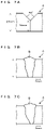
- FIG. 7A is a schematic view illustrating the cross-section of a base material to be welded
- FIG. 7B is a schematic view illustrating the cross-section of a bead portion after welding
- FIG. 7C is a schematic view illustrating the cross-section of a bead portion after welding
- FIG. 8 is a schematic diagram illustrating a configuration example of an intermediate wire feeding source according to Embodiment 2;
- FIG. 9 is a block diagram illustrating a configuration example of a power supply device according to Embodiment 3.
- FIG. 10 is a block diagram illustrating a configuration example of a power supply
- FIG. 11 is a flowchart illustrating a processing procedure for each power supply concerning power supply control.
- FIG. 12 is a flowchart illustrating a processing procedure for each power supply concerning power supply control.
- FIG. 1 is a schematic diagram illustrating a configuration example of an arc welding system according to Embodiment 1.
- FIG. 2 is a schematic diagram illustrating a configuration example of an intermediate wire feeding source 41 according to Embodiment 1.
- the arc welding system according to the present embodiment is a gas shield arc welding machine of a consumable electrode type that is capable of butt welding a base material A having a plate thickness of 9 mm to 30 mm by a single pass, and includes: a welding robot 1 , a robot control device 2 , a wire feeding source 3 , a wire feeding device 4 and a power supply device 5 .
- the welding robot 1 automatically performs arc welding of the base material A.
- the welding robot 1 includes a base 11 fixed to an appropriate position on a floor surface. To the base 11 , multiple arms 12 are rotatably connected via shafts (not illustrated). A welding torch 13 is held at the distal end of the arm 12 connected at the distal end side. A motor is provided at the connecting portion of the arms 12 , so that each arm 12 pivots around the shaft by the rotary drive force of the motor. The rotation of the motor is controlled by the robot control device 2 .
- the robot control device 2 may move the welding torch 13 with respect to the base material A in the upper, lower, front, back, left and right directions by rotating the arms 12 .
- an encoder is located that outputs a signal indicating a rotated position of each arm 12 to the robot control device 2 , which recognizes the position of the welding torch 13 based on the signal output from the encoder.
- the welding torch 13 is made of conductive material such as copper alloy, and has a cylindrical contact chip which guides welding wire W to the base material A to be welded while supplying welding current required to generate arc 7 (see FIG. 5 ).
- the contact chip makes contact with welding wire W penetrating into the contact chip, and supplies welding current to the welding wire W.
- the welding torch 13 has a hollow cylindrical shape surrounding the contact chip, and has a nozzle for spraying shield gas to the base material A through an opening at the tip end thereof.
- the shield gas is to prevent oxidation of the base material A melted by the arc 7 as well as the welding wire W.
- the shield gas is, for example, carbon dioxide gas, mixed gas containing carbon dioxide gas and argon gas, or inert gas such as argon.
- a water flow path for cooling the welding torch 13 with water is formed inside the contact chip and the nozzle.
- the contact chip and nozzle are connected with each other at the non-distal side, which is provided, on the outer side, with an inlet through which cooling water flows in and an outlet through which water passed through the water flow path flows out.
- the water flow path is a pathway from the inlet through the non-distal portion of the contact chip, the distal portion of the contact chip, the non-distal portion of the contact chip, the non-distal portion of the nozzle and the distal portion of the nozzle, to the outlet.
- the wire feeding source 3 accommodates the welding wire W so as to veer out the welding wire W to the welding torch 13 .
- the welding wire W is, for example, a solid wire having a diameter of 0.8 mm to 1.6 mm, and functions as a consumable electrode.
- the wire feeding source 3 is, for example, a pack wire.
- the pack wire includes a cylindrical housing in which the welding wire W helically coiled with its bottom end located at the bottom, and is configured to sequentially veer out the welding wire W through a hole (not illustrated) opened at the top end.
- the pack wire is an example of the wire feeding source 3 , and may be a reel wire made by a winding of the welding wire W.
- the wire feeding device 4 is provided with an intermediate wire feeding source 41 that is disposed between the wire feeding source 3 and the welding torch 13 and is configured to temporarily accommodate the welding wire W fed from the wire feeding source 3 and to feed the accommodated welding wire W to the welding torch 13 .
- the intermediate wire feeding source 41 is to absorb the difference in the wire feeding speed between different parts in the feed path, and also to reduce the feeding load of the welding wire W on the welding torch 13 side.
- the intermediate wire feeding source 41 has a hollow substantially-rectangular-parallelepiped housing 41 a that accommodates the welding wire W.
- the housing 41 a has a flat placement surface 41 m that can be placed at a location such as on a floor.
- an inlet part 41 b through which the welding wire W fed from the wire feeding source 3 is introduced and an outlet part 41 c through which the welding wire W accommodated inside the housing 41 a is sent out are formed.
- the wire feeding source 3 and the inlet part 41 b of the intermediate wire feeding source 41 are connected via a first conduit cable 4 a through which the welding wire W passes.
- a pull-out feeding part 41 d (first feeding part) is provided, which pulls out the welding wire W from the wire feeding source 3 and pulls the welding wire W into the housing 41 a through the inlet part 41 b .
- the pull-out feeding part 41 d has a pair of rollers that are opposed to each other at positions where the rollers can hold the welding wire W introduced through the inlet part 41 b between them. At least one of the rollers is rotary driven by a pull-out feeding motor 41 f which is capable of controlling the speed.
- the pull-out feeding part 41 d may feed the welding wire W at a speed of 100 meters per minute, for example.
- the pull-out feeding part 41 d rotates the rollers based on a feed control signal output from the power supply device 5 .
- the welding wire W pulled into the housing 41 a from the first conduit cable 4 a through the inlet part 41 b is bent into an arbitrary shape, and a predetermined amount of welding wire W is accommodated into the housing 41 a .
- the welding wire W is accommodated while being bent into loops.
- a member for guiding the welding wire W may be provided inside the housing 41 a so that the welding wire W is accommodated in a predetermined spatial area without being entangled.
- a wire guiding part 41 e is provided, which guides the welding wire W accommodated inside the intermediate wire feeding source 41 and sends out the welding wire W to the outside the housing 41 a through the outlet part 41 c .
- the wire guiding part 41 e has a pair of rollers that are opposed to each other at positions where the rollers can hold the welding wire W between them and guide it to the outlet part 41 c .
- the rollers may be configured to be rotary driven by a motor which rotates in synchronization with the pull-out feeding motor 41 f , or be passively rotated.
- the wire feeding device 4 is provided with a push feeder 42 that pulls out the welding wire W from the intermediate wire feeding source 41 and pushes out the pulled-out welding wire W to the welding torch 13 .
- the push feeder 42 is located, for example, at the arm 12 of the welding robot 1 .
- the push feeder 42 is connected to the outlet part 41 c of the intermediate wire feeding source 41 by a second conduit cable 4 b through which the welding wire W passes, and is connected to the welding torch 13 by a third conduit cable 4 c .
- the intermediate wire feeding source 41 is arranged side by side with and in the vicinity of the welding robot 1 .
- the push feeder 42 includes a push-out feeding part 42 a (second feeding part) that pulls out the welding wire W from the intermediate wire feeding source 41 and pushes out the pulled-out welding wire W to the welding torch 13 .
- the push-out feeding part 42 a has a pair of rollers that are opposed to each other at positions where the rollers can hold the welding wire W between them. At least one of the rollers is rotary driven by a pull-out feeding motor (not illustrated) which is capable of controlling the speed.
- the push-out feeding part 42 a may feed the welding wire W at a speed of 100 meters per minute, for example.
- the push-out feeding part 42 a rotates the rollers based on a feed control signal output from the power supply device 5 .
- the intermediate wire feeding source 41 includes an accommodated amount detection unit 41 g that detects the accommodated amount of the welding wire W, a feed control unit 41 h that controls the rotation of the pull-out feeding motor 41 f , and a control signal input unit 41 i to which a feed control signal output from the power supply device 5 is input.
- the accommodated amount detection unit 41 g includes, for example, a bar member 41 j which has one end rotatably fixed and the other end making contact from the outer circumferential side with the circular arc portion of the welding wire W accommodated in a loop-like form and a rotary position sensor which detects the rotational position of the bar member 41 j . If the accommodated amount of the welding wire W is increased or decreased, the diameter of the loop of the welding wire W accommodated inside the housing 41 a changes as illustrated by the two-dot chain lines in FIG. 2 , and the bar member 41 j pivots around the one end described above.
- the rotary position sensor may detect the rotational position of the bar member 41 j to detect the accommodated amount of the welding wire W, and output the detection result to the feed control unit 41 h.
- the accommodated amount detection unit 41 g provided with the rotary position sensor is a mere example, and the accommodated amount of welding wire W may be optically detected with the use of an infrared sensor or the like. Moreover, a limit switch which is in contact with the accommodated welding wire W and is turned on or off in accordance with the accommodated amount of the welding wire W may also be used to configure the accommodated amount detection unit 41 g.
- the feed control unit 41 h corrects the feed control signal input to the control signal input unit 41 i based on the detection result obtained by the accommodated amount detection unit 41 g , and accommodates a predetermined amount of welding wire W into the housing 41 a by controlling the rotation of the pull-out feeding motor 41 f in accordance with the corrected feed control signal.
- the feed control unit 41 h rotates the pull-out feeding motor 41 f at a speed higher than the rotational speed instructed by the feed control signal. Moreover, if the accommodated amount of the welding wire W is more than the predetermined amount, the feed control unit 41 h rotates the pull-out feeding motor 41 f at a speed lower than the rotational speed instructed by the feed control signal.
- the power supply device 5 is connected to the contact chip of the welding torch 13 and the base material A via the power supply cable, and includes a power supply unit 51 that supplies welding current and a feeding speed control unit 52 that controls the feeding speed of the welding wire W.
- the power supply unit 51 includes a power supply circuit that outputs PWM-controlled direct current, a signal processing unit that controls the operation of the power supply circuit, a voltage detection unit, a current detection unit, and so forth.
- the voltage detection unit detects voltage applied to the welding torch 13 and the base material A, and outputs a voltage value signal indicating the detected voltage value to the signal processing unit.
- the current detection unit detects, for example, welding current supplied from the power supply device 5 to the welding wire W via the welding torch 13 and flows through the arc 7 , and outputs a current value signal indicating the detected current value to the signal processing unit.
- the signal processing unit outputs a signal for performing PWM control on the power supply circuit to the power supply circuit based on a voltage value signal, a current value signal and a set value for welding conditions, and so forth.
- the power supply circuit includes, for example, an AC-DC converter performing AC-DC conversion on commercial alternating current, an inverter circuit converting direct current subjected to AC-DC conversion into desired alternating current by switching, and a rectification circuit rectifying the alternating current obtained by conversion.
- the power supply circuit performs PWM control on the inverter circuit in accordance with the signal output from the signal processing unit, and outputs predetermined welding current and voltage to the welding wire W. For example, welding voltage that varies periodically is applied between the base material A and the welding wire W, and the welding current flows.
- the power supply device 5 is so configured that an output instruction signal is input thereto from the robot control device 2 via a control communication line, and the power supply unit 51 starts supplying welding current to the power supply circuit while the output instruction signal serves as a trigger.
- FIG. 3 is a flowchart illustrating a procedure of an arc welding method according to the present embodiment.
- a pair of base materials A to be joined by welding are placed at the arc welding device, and various settings are performed for the power supply device 5 (step S 11 ).
- a first base material Al and a second base material A2 having a plate-like shape are prepared and disposed in a predetermined welding work position by making end faces a1 and a2 that are to be welded face each other.
- the first base material A1 and the second base material A2 are steel plates made of, for example, soft steel, carbon steel for machine structural use or alloy steel for machine structural use, having a thickness in a range from 9 mm to 30 mm.
- the power supply device 5 then sets the welding condition of welding current within a range at the frequency of 10 Hz to 1000 Hz, the average current of 300 A or larger and the current amplitude of 50 A or higher.
- the conditions for welding current may be set by a welding worker entirely, or the power supply device 5 may accept implementation of the welding method according to the present embodiment through an operation unit so as to set all the conditions automatically. Furthermore, the power supply device 5 may accept a part of the welding conditions such as average current through the operation unit and determine the rest of the welding conditions conforming to the accepted part of the welding conditions so as to semi-automatically set the conditions.
- the power supply device 5 determines whether or not the condition for starting output of the welding current is satisfied (step S 12 ). More specifically, the power supply device 5 determines whether or not an output instruction signal for welding is input. If it is determined that no output instruction signal is input and the output starting condition of welding current is not satisfied (step S 12 : NO), the power supply device 5 waits in the state of waiting input of an output instruction signal.
- the feeding speed control unit 52 of the power supply device 5 outputs to the wire feeding device 4 a feed control signal for instructing to feed wire, so that the welding wire W is fed at a predetermined speed (step S 13 ).
- the feeding speed of the welding wire W is set within the range of, for example, approximately 5 to 100 meters per minute.
- the welding wire W may preferably be fed at a speed of 5 meters per minute or higher.
- the buried arc state may be maintained well.
- the feeding speed control unit 52 decides the feeding speed in accordance with the average current setting signal output from the average current setting circuit. It may also be configured that a welding worker may directly set the feeding speed of wire.
- the power supply unit 51 of the power supply device 5 detects welding voltage and welding current at the voltage detection unit and the current detection unit (step S 14 ), and performs PWM control so that the frequency, current amplitude and average current for the detected welding current corresponds to the set welding conditions and the welding current periodically varies (step S 15 ).
- welding may be performed in the state where the external characteristic of the power supply device 5 , that is, the rate of change in the voltage with respect to the rate of change in the welding current is in the range from ⁇ 40V/100 A to ⁇ 2V/100 A.
- the rate of change in the voltage with respect to the rate of change in the welding current is in the range from ⁇ 40V/100 A to ⁇ 2V/100 A.
- the power supply unit 51 of the power supply device 5 determines whether or not the output of welding current is stopped (step S 16 ). More specifically, the power supply device 5 determines whether or not an input of the output instruction signal continues. If it is determined that the input of the output instruction signal continues and the output of welding current is not stopped (step S 16 : NO), the power supply unit 51 returns the processing to step S 13 and continues outputting welding current.
- step S 16 If it is determined that the output of the welding current is stopped (step S 16 : YES), the power supply unit 51 returns the processing to step S 12 .
- FIGS. 4A, 4B and 4C are graphs illustrating variation in set voltage, welding voltage and welding current.
- FIG. 5 is a schematic diagram illustrating an arc welding method according to the present embodiment.
- the horizontal axis in each graph illustrated in FIGS. 4A to 4C indicates time, whereas the vertical axes in the graphs illustrated in FIGS. 4A to 4C indicate set voltage for the power supply device 5 , welding voltage between the base material A and the welding wire W, and welding current flowing through the arc 7 , respectively.
- the power supply unit 51 controls the welding current such that the frequency thereof ranges from 10 Hz to 1000 Hz, the average current is 300 A or larger and the current amplitude is 50 A or higher.
- the power supply unit 51 controls the welding current such that the frequency thereof ranges from 50 Hz to 300 Hz, the average current ranges from 400 A to 1000 A, and the current amplitude ranges from 100 A to 300 A.
- the power supply unit 51 controls the welding current such that the frequency of the power supply device 5 ranges from 100 Hz to 200 Hz, the current amplitude ranges from 200 A to 300 A, and the average current ranges from 500 A to 800 A, as illustrated in FIG. 4C .
- the welding wire W may be fed at the speed of approximately 40 meters per minute.
- the set voltage is assumed as rectangular wave-like voltage with the frequency of 100 Hz and voltage amplitude of 30V as illustrated in FIG. 4A , while the welding voltage as illustrated in FIG.
- the power supply device 5 performs control on the set voltage with the frequency of 100 Hz so that the welding current has the current amplitude of 240 A and the average current of 530 A, for example. Furthermore, the power supply device 5 controls feeding of the welding wire W at the speed of approximately 40 meters per minute. While the welding voltage varies in the range from 27V to 41V, the variation range in the welding voltage changes due to the influence of various impedances.
- a concave melted portion 6 is formed at the base material A, which is made of the molten metal of the welding wire W and the base material A melted by the heat of the arc 7 generated between the tip end of the welding wire W and a to-be-welded portion.
- the arc 7 is then photographed with a high-speed camera, to find that its state is periodically changed between the first state where the arc 7 is generated between the tip end of the welding wire W and the bottom part of the melted portion 6 , and the second state where the arc 7 is generated between the tip end and a side part of the melted portion 6 .
- the state is repeatedly switched between the first state where the arc 7 is directed from the tip end of the welding wire W to the bottom part of the melted portion 6 and the second state where the arc 7 is directed from the tip end of the welding wire W to a side part of the melted portion 6 .
- the molten metal tends to flow in the direction in which the tip end of the welding wire W is buried
- the arc 7 is directed to a side wall part of the melted portion 6 in the second state
- the molten metal of the melted portion 6 is pushed back in the direction away from the welding wire W, and the melted portion 6 is stabilized in a concave state.
- the tip end of the melted welding wire W falls into a molten pool located at the bottom part of the melted portion 6 and is thereby shortened.
- the first state and the second state are switched from each other at a frequency ranging from 100 Hz to 200 Hz, which allows micro vibration of molten metal to occur at a frequency higher than the large corrugation frequency, preventing the molten metal from having coarse corrugation.
- the percentage of such periods may be different from each other.
- the breadth of the vertical displacement of the tip end of the welding wire W may be adjusted while suppressing corrugation of the molten metal.
- the tip end of the welding wire W is more likely to be held at a position higher than the bottom part of the melted portion 6 .
- the amount of heat input to the upper part of the base material A may be increased and thus bead forming ability may be improved.
- FIG. 6 is a graph illustrating the relationship between the feeding amount of welding wire W and the depth of weld penetration in the butt welding by large current buried arc 7 .
- the horizontal axis represents the amount of wire fed per minute whereas the vertical axis represents the maximum depth of weld penetration.
- the graph with circled plots, the graph with triangle plots and the graph with x plots represent experimental results showing the relationship between the fed amount of wire and the depth of weld penetration at the time of using the welding wire W with the wire diameters of 1.2 mm, 1.4 mm and 1.6 mm, respectively.
- the experimental conditions will be described below.
- the welding wire W employed are YGW11 with the wire diameters of 1.2 mm and 1.4 mm, and YGW12 with the wire diameter of 1.6 mm.
- the welding speed is 30 cm per minute.
- the distance between the contact chip and the base material A is 25 mm, and the shield gas is carbon dioxide.
- the external characteristic is ⁇ 10V/100 A. Voltage varying with the voltage amplitude of ⁇ 10V and the frequency of 100 Hz is then applied between the welding torch 13 and the base material A.
- the graph in FIG. 6 shows that the weld penetration per wire feeding amount is deeper as the wire diameter is increased. Moreover, at the wire diameters of 1.2 mm and 1.4 mm with which comparatively stable bead formation may be obtained, the depth of maximum weld penetration of approximately 16 mm to 19 mm may be obtained. Meanwhile, such a tendency is observed that the increase in the wire diameter lowers the upper limit of the amount of wire feeding which can stably maintain large current buried arc 7 .
- FIGS. 7A, 7B and 7C are schematic views illustrating the cross-section of the base material A to be welded and a bead portion after welding.
- FIG. 7A is a schematic view illustrating the cross-section of the base material A to be welded by butt welding.
- the base material A is a thick plate with the thickness of 25 mm and has a Y groove.
- the groove angle of the Y groove is 90 degrees and the dimension of a root face corresponds to 16 mm.
- FIG. 7B illustrates the cross section of a bead B obtained by butt welding at the mean current of 720 A, average voltage of 47V, voltage amplitude of ⁇ 10V, frequency of 100 Hz and external characteristic of ⁇ 10V/100 A.
- FIG. 7C illustrates the cross section of a bead B obtained by butt welding at the mean current of 720 A, average voltage of 47V, voltage amplitude of ⁇ 10V, frequency of 100 Hz and external characteristic of ⁇ 20V/100 A.
- the control method for the welding current and voltage is not specifically limited.
- welding may be performed while periodically switching between the first state where the feeding speed of the welding wire W, welding current and voltage are high and the second state where the feeding speed of the welding wire W, welding current and voltage are low.
- welding may be performed while switching between the first state where the feeding speed of the welding wire W is 50 m/minute, the welding current is 620 A and the voltage is 55V, and the second state where the feeding speed of the welding wire W is 60 m/minute, the welding current is 700 A and the voltage is 64V at a frequency in the range from 0.2 to 2 Hz.
- a liquid drop concerning welding has a transition form of drop transition or transition in which the arc rotates while moving back and forth on the same plane like a pendulum, resulting in deeper penetration of the welding wire W.
- a liquid drop has a rotating transition, resulting in shallower penetration of the welding wire W.
- the welding voltage may be fixed while the welding current and the feeding speed of the welding wire W are periodically changed when welding is performed.
- the following welding conditions may appropriately be utilized that make it possible to perform pierce welding of the base material A by maintaining the buried arc state.
- a thick plate with the thickness of 9 mm may be welded by pierce welding.
- a thick plate with the thickness of 12 mm may be welded by pierce welding.
- a thick plate having the thickness of 16 mm may be welded by pierce welding.
- a thick plate with the thickness of 19 mm may be welded by pierce welding.
- base material A having a Y groove is butt-welded
- a base material A having a single bevel groove, I groove or any other groove may also be welded. It is also possible to weld the base material A with no groove.
- butt joint has been described as an example of butt welding, the joint form of welding is not particularly limited.
- the feeding load of the welding wire W on the welding torch 13 side may be reduced. This makes it possible to stably feed the welding wire W to the welding torch 13 at a required speed so as to achieve single pass welding for a thick plate.
- the amount of the welding wire W accommodated in the housing 41 a is monitored so as to accommodate a predetermined amount of welding wire W in the intermediate wire feeding source 41 , which enables stable feeding of the welding wire W from the intermediate wire feeding source 41 to the welding torch 13 .
- the welding wire W itself is accommodated in the housing 41 a of the intermediate wire feeding source 41 , so that a sufficient amount of welding wire W necessary for stable feeding of the welding wire W may more preferably be accommodated, compared to a cushioning mechanism configured by simply bending a conduit cable.
- the housing 41 a accommodates the welding wire W itself, the friction resistance between the welding wire W and the conduit cable would not be a problem, allowing the welding wire W to be fed to the welding torch 13 at a reduced load.
- the welding wire W may stably be fed from the intermediate wire feeding source 41 to the welding torch 13 .
- the welding wire W may stably be fed to the welding torch 13 .
- the intermediate wire feeding source 41 is so configured that can be put on a flat surface such as a floor, and therefore may freely be placed at any position between the wire feeding source 3 and the welding torch 13 .
- Embodiment 1 described the example where the pull-out feeding part 41 d is located inside the housing 41 a of the intermediate wire feeding source 41 , the pull-out feeding part 41 d and the intermediate wire feeding source 41 may also be formed as separate units.
- the position of the separate pull-out feeding part 41 d is not necessarily limited, and may be located at the wire feeding source 3 .
- the position of the intermediate wire feeding source 41 is not particularly limited but may be at the arm 12 of the welding robot 1 .
- FIG. 8 is a schematic diagram illustrating a configuration example of an intermediate wire feeding source 141 according to Embodiment 2.
- the intermediate wire feeding source 141 according to Embodiment 2 has a housing 141 a similar to that in Embodiment 1, and is provided with an inlet part 141 b at the side face of the housing 141 a , through which the welding wire W fed from the wire feeding source 3 is introduced in a horizontal direction (first direction), and with an outlet part 141 c at the upper face of the housing 141 a , through which the welding wire W accommodated inside the housing 141 a is sent out in an upward perpendicular direction crossing the horizontal direction.
- the welding wire W pulled into the housing 141 a is accommodated in a state of being bent in an arc-like form between the inlet part 141 b and the outlet part 141 c.
- the accommodated amount detection unit 141 g is provided with a bar member 141 j with one end rotatably fixed thereto. At the other end of the bar member 141 j , a pair of curvature detection rollers 141 k that hold the bent portion of the welding wire W between them are rotatably supported. If the accommodated amount of the welding wire W is increased or decreased, the curvature of the welding wire W accommodated in the housing 141 a changes as illustrated in FIG. 8 , and the bar member 141 j pivots around the one end described above.
- the accommodated amount detection unit 141 g is a rotary position sensor that detects the rotational position of the bar member 141 j , and by detecting the rotary position of the bar member 141 j , the accommodated amount detection unit 141 g can detect the accommodated amount of the welding wire W, and outputs a signal indicating the accommodated amount to the power supply device 5 via the input/output unit 141 i .
- the power supply device 5 receives the signal output from the intermediate wire feeding source 141 , and outputs a feed control signal calculated based on the received signal to the intermediate wire feeding source 141 .
- the feed control signal output from the power supply device 5 is input to the input/output unit 141 i of the intermediate wire feeding source 141 .
- the pull-out feeding motor 41 f rotates at a speed according to the feed control signal, and a predetermined amount of welding wire W is accommodated in the housing 141 a.
- the welding wire W is accommodated into the intermediate wire feeding source 141 in the state of being bent in an arc-like form between the inlet part 141 b and the outlet part 141 c . Therefore, compared to the case where the welding wire W is largely bent in loops and is accommodated into the housing 141 a , the feeding load may be reduced. Compared to the case where the welding wire W is accommodated in loops, the internal structure of the housing 141 a may be simplified.
- FIG. 9 is a block diagram illustrating a configuration example of the power supply device 5 according to Embodiment 3.
- the power supply device 5 according to Embodiment 3 includes multiple power supplies 8 that are connected in parallel to a common load concerning arc welding, to feed electricity to the load.
- the power supplies 8 are connected with each other by a communication line.
- the multiple power supplies 8 are insulating switching power supplies, which perform AC/DC conversion on the alternating current into required direct current, and supply the converted direct current to the load.
- One power supply 8 of the multiple power supplies 8 functions as a master power supply that controls the output of each power supply 8 by transmitting PWM control information to a different power supply 8 via a communication line.
- the different power supply 8 receives the PWM control information transmitted from the one power supply 8 , and functions as a slave power supply that controls the output based on the received PWM control information.
- the power supply 8 which functions as a master power supply is appropriately referred to as a first power supply 8
- the power supply 8 which functions as a slave power supply is referred to as a second power supply 8 .
- a single second power supply 8 or multiple second power supplies 8 may be provided.
- the second power supply 8 detects current output from its own device to the load, and transmits the current information indicating the detected current to the first power supply 8 via a communication line.
- the first power supply 8 receives the current information transmitted from the second power supply 8 , and calculates the total current output from the power supply device 5 to the load by adding the current indicated by the current information and the current detected by its own device.
- the first power supply 8 detects voltage to be output from its own device to the load, and calculates PWM control information for controlling the output of each power supply 8 constituting the power supply device 5 based on the voltage obtained by detection and the total current.
- the first power supply 8 controls the output of its own device based on the PWM control information calculated as described above, while controlling the operation of each power supply 8 by transmitting the PWM control information to the second power supply 8 as described above.
- each power supply 8 may function as either one of the master power supply and the slave power supply by switching the operation mode. Moreover, the power supply 8 may function as a single independent power supply 8 by switching the operation mode.
- FIG. 10 is a block diagram illustrating a configuration example of the power supplies 8 .
- the power supply device 5 is constituted by two power supplies, i.e. the first power supply 8 and the second power supply 8 .
- Each of the first power supply 8 and the second power supply 8 is a constant voltage characteristic power supply with the maximum output of 500 A, for example.
- the power supply device 5 may output the current of 1000 A at maximum by synchronous control of the first power supply 8 and the second power supply 8 . Since the first and second power supplies 8 are configured in the same manner, the configuration of one of the power supplies 8 will mainly be described.
- the power supply 8 includes an operation panel 80 , an input unit 81 , a rectifier 82 , an inverter 83 , a transformer 84 , a rectifier smoother 82 , a voltage detection unit 86 , a current detection unit 87 , a main control unit 88 and a signal processing unit 89 .
- the input unit 81 is an input terminal connected to a three-phase AC power supply (not illustrated), for example.
- the input unit 81 is connected to the rectifier 82 , and the three-phase alternating current applied to the input terminal is input to the rectifier 82 .
- the rectifier 82 is, for example, a diode bridge circuit.
- the diode bridge has a circuit configuration where three sets of serial circuits constituted by two forwardly connected diodes (not illustrated) are arranged in parallel.
- a smooth capacitor (not illustrated) is located at an output terminal of the diode bride circuit.
- the rectifier 82 full-wave rectifies the alternating current input from the three-phase AC power supply through the input unit 81 , and outputs the direct current smoothed at the smooth capacitor to the inverter 83 .
- the inverter 83 is a circuit which converts the direct current rectified and smoothed at the rectifier 82 into high frequency alternating current and outputs the converted current to the transformer 84 .
- the inverter 83 is, for example, a full-bridge circuit constituted by four switching elements.
- the full bridge circuit has a circuit configuration where two sets of legs including two serially-connected switching elements are connected in parallel.
- Each of the switching elements is a power device such as an insulated gate bipolar transistor (IGBT) or a metal-oxide semiconductor field effect transistor (MOSFET), for example.
- IGBT insulated gate bipolar transistor
- MOSFET metal-oxide semiconductor field effect transistor
- the transformer 84 transforms the alternating current output from the inverter 83 , and outputs the transformed alternating current to the rectifier smoother 85 .
- the transformer 84 is provided with a primary coil and a secondary coil that are wound around cores and are magnetically coupled with each other, the primary coil being connected to the inverter 83 while the secondary coil being connected to the rectifier smoother 85 .
- the rectifier smoother 85 is a circuit for rectifying and smoothing the alternating current output from the transformer 84 .
- the voltage and current of the rectified direct current are output from the positive output terminal 8 a and the negative output terminal 8 b to a load.
- the rectifier smoother 85 is constituted by, for example, a full-wave rectifying circuit using a center tap, a smoothing circuit using a reactor, and so forth.
- the load is for arc welding, for example, and employs welding wire W, a base material A, an arc 7 from which shield gas is ionized, or the like.
- the positive output terminal 8 a is electrically connected to the welding wire W via a positive side feeder and the welding torch 13
- the negative output terminal 8 b is connected to the base material A via a negative-side feeder.
- the voltage detection unit 86 is, for example, a circuit that is connected to the output side of the rectifier smoother 85 , detects voltage output from its own device to the load, and outputs a voltage value signal indicating the detected voltage value to the main control unit 88 .
- the current detection unit 87 is, for example, a circuit that is located at the output side of the rectifier smoother 85 , detects current output from its own device to the load, and outputs a current value signal indicating the detected current value to the main control unit 88 .
- the current detection unit 87 is a hall current sensor provided with a magneto-electric transducer such as a hall element, for example.
- the main control unit 88 is a processor including a central processing unit (CPU), a ROM, a RAM, an interface and the like, and controls the operation of the entire power supply 8 .
- a control terminal 8 c is connected to the interface of the main control unit 88 .
- a control communication line of a welding machine is connected to the control terminal 8 c of the power supply 8 serving as a master power supply, and a drive instruction signal output from the welding machine is input to the control terminal 8 C.
- the main control unit 88 monitors the input state of the drive instruction signal, and outputs a drive request for operating the inverter 83 to the signal processing unit 89 in the case where the drive instruction signal is input. No drive instruction signal is input to the control terminal 8 c of the power supply 8 serving as a slave power supply.
- the interface of the main control unit 88 is connected to a voltage detection unit 86 and a current detection unit 87 , to which a voltage value signal and a current value signal are input.
- the main control unit 88 AD-converts the input voltage value signal and current value signal, and outputs voltage information and current information obtained by AD conversion to the signal processing unit 89 .
- the main control unit 88 is connected to the operation panel 80 , and a signal corresponding to the operation to the operation panel 80 is input.
- the main control unit 88 accepts the operation to the operation panel 80 by monitoring the signal.
- the main control unit 88 may accept selection of the operation mode of the power supply 8 through the operation panel 80 .
- the operation mode includes a master power mode (first control form) causing the power supply 8 to function as a master power supply, a slave power mode (second control form) causing the power supply 8 to function as a slave power supply, and a single power mode causing the power supply 8 as a single power supply.
- the main control unit 88 is configured to display the operation state of its own device on the operation panel 80 by outputting a display instruction signal for displaying various operation states such as the operation mode, output voltage, output current or the like of its own device to the operation panel 80 .
- the main control unit 88 of the power supply 8 operating as a master power supply outputs a wire feeding control signal for controlling feed of the welding wire W in a welding machine from the control terminal 8 c to the welding machine. It is noted that the power supply 8 operating as a slave power supply outputs no wire feeding control signal.
- the signal processing unit 89 is a digital signal processor (DSP) outputting a PWM signal to a switching element constituting the inverter 83 and performing PWM control for on/off of the switching element, and includes a control information calculation unit 89 a , a PWM control unit 89 b and a communication unit 89 c .
- the signal processing unit 89 is connected to the inverter 83 and the main control unit 88 . Voltage information, current information, drive request and the like output from the main control unit 88 are input to the signal processing unit 89 .
- the signal processing unit 89 stores therein the operation mode of its own device, and the details of its signal processing depends on the operation mode of the power supply 8 . The details of signal processing will be described later.
- the control information calculation unit 89 a is a function part that calculates PWM control information for controlling the voltage or current to be output to the load by controlling the operation of the inverter 83 .
- the PWM control information is information indicating the pulse width and pulse waveform of the PWM signal to be output to the inverter 83 .
- the control information calculation unit 89 a calculates PWM control information for performing PWM control on the inverter 83 of its own device based on the voltage information and current information output from the main control unit 88 , that is, on the voltage and current detected at its own device.
- the control information calculation unit 89 a calculates PWM control information for performing PWM control on the inverter 83 of the first and second power supplies 8 based on the voltage information and current information of its own device output from the main control unit 88 , and on the current information concerning a different power supply 8 . That is, the control information calculation unit 89 a calculates PWM control information based on the voltage and current detected at its own device and the current detected at a different power supply 8 which is a slave power supply. It is noted that the current information detected at the different power supply 8 may be received by the communication unit 89 c.
- control information calculation unit 89 a will not calculate PWM control information.
- the PWM control unit 89 b is a function part that generates a PWM signal having a required pulse width and pulse waveform using PWM control information and outputs the generated PWM signal to the inverter 83 .
- the PWM control unit 89 b outputs alternating current from the inverter 83 by alternately switching the switching element of the full bridge circuit between the on state and the off state in a crisscross manner.
- the PWM control unit 89 b In the case where the operation mode is the single power mode or master power mode, the PWM control unit 89 b generates a PWM signal using the PWM control information calculated by the control information calculation unit 89 a of its own device.
- the PWM control unit 89 b In the case where the operation mode is the slave power mode, the PWM control unit 89 b generates a PWM signal using the PWM control information calculated at a different power supply 8 .
- the PWM control information calculated at the different power supply 8 may be received by the communication unit 89 c .
- the PWM signal for its own device and the PWM signal for the different power supply 8 will be approximately the same signal as a result.
- the PWM control unit 89 b In the case where they have different output capacities, the PWM control unit 89 b generates a PWM signal for which the difference in the output capacities is corrected using the PWM control information calculated at the different power supply 8 .
- the PWM signal for its own device and the PWM signal for the different power supply 8 will be different signals.
- the communication unit 89 c is a communication circuit for transmitting and receiving various information to/from the different power supply 8 .
- the communication unit 89 c transmits and receives information according to the host control interface (HCl) communication protocol.
- HCl host control interface
- the signal processing unit 89 transmits through the communication unit 89 c the operation information indicating the operation state of the inverter 83 of its own device and the PWM control information calculated by the control information calculation unit 89 a to the different power supply 8 operating in the slave power mode.
- the power supply 8 receives, by the communication unit 89 c , the operation information and PWM control information transmitted from the power supply 8 operating in the master power mode.
- the signal processing unit 89 transmits through the communication unit 89 c current information indicating current being output from its own device to the load, operation information indicating the operation state of the inverter 83 of its own device and abnormality information indicating the presence/absence of its own device, to the power supply 8 operating in the master power mode.
- the abnormality information is information indicating, for example, excess current and/or abnormal stop.
- the power supply 8 which is the master power supply receives, by the communication unit 89 c , the current information, operation information and abnormality information transmitted from the power supply 8 operating in the slave power mode.
- the operation panel 80 includes a current display unit and a voltage display unit indicating the current and voltage that are being output to the load.
- the main control unit 88 causes the current display unit to display the value of total current obtained by adding the current being output from each power supply 8 .
- the main control unit 88 also causes the voltage display unit to display the value of the voltage obtained by detecting it at its own device.
- the main control unit 88 causes the current display unit and voltage display unit to display predetermined information indicating that its own device is being driven.
- the predetermined information is text information such as “being driven” or “RUN” for example, the content of information to be displayed is not particularly limited but may also include a configuration where the display pixels or segments constituting the current display unit and voltage display unit are all turned on or off.
- the main control unit 88 causes the current display unit and voltage display unit to display the values of current and voltage being output from its own device.
- the operation panel 80 includes an operation unit for switching the operation mode of the power supply 8 and an operation mode display unit for displaying the current operation mode of its own device.
- the operation unit may be, for example, a sealed tactile switch or a push button switch.
- the main control unit 88 of the power supply 8 switches the current operation mode to a different operation mode.
- the signal processing unit 89 stores the current operation mode
- the main control unit 88 switches the operation mode of the signal processing unit 89 by outputting a mode switching instruction to the signal processing unit 89 .
- the operation mode is switched in turns, from the single power mode, the master power mode, the slave power mode and back to the single power mode . . . , every time the operation unit is operated, for example.
- the operation mode display unit has multiple light emitting elements.
- the light emitting elements include, for example, a light emitting element which is turned on in the master power mode and a light emitting element which is turned on in the slave power mode.
- FIGS. 11 and 12 show a flowchart illustrating a processing procedure for each power supply 8 concerning power feeding control. Here, description is made on the processing of the first power supply 8 operating in the master power mode and the second power supply 8 operating in the slave power mode.
- the main control unit 88 detects the current and voltage being output from its own device to the load by the current detection unit 87 and the voltage detection unit 86 (step S 51 ).
- the main control unit 88 outputs the detected and obtained current information and voltage information to the signal processing unit 89 .
- the signal processing unit 89 in the master power mode calculates PWM control information based on the current and voltage indicated by the current information and voltage information (step S 52 ). Since the slave power supply 8 is not in operation yet at the time of activation, the current and voltage detected at the first power supply 8 are used to calculate PWM control information, for example.
- the signal processing unit 89 then performs PWM control on the inverter 83 based on the calculated PWM control information (step S 53 ). Subsequently, the signal processing unit 89 transmits the operation information indicating the operation state of the inverter 83 as well as the PWM control information to the second power supply 8 which is the slave power supply through the communication unit 89 c (step S 54 ).
- the operation information is, for example, information indicating whether or not the inverter 83 is being driven.
- the signal processing unit 89 in the slave power mode receives, by the communication unit 89 c , the operation information and PWM control information transmitted from the first power supply 8 (step S 55 ).
- the signal processing unit 89 in the slave power mode then confirms that the master power supply is being driven based on the operation information, and performs PWM control on the inverter 83 of its own device based on the received PWM control information (step S 56 ).
- the communication unit 89 c performing transmission at step S 54 corresponds to a control information transmission unit
- the communication unit 89 c performing reception at step S 55 corresponds to a control information reception unit
- the main control unit 88 of the second power supply 8 causes the operation panel 80 to display the fact that it is being driven if its own device is normally operating (step S 57 ).
- the main control unit 88 causes the current display unit and voltage display unit to display that it is being driven.
- the main control unit 88 detects current being output from its own device to the load by the current detection unit 87 (step S 58 ).
- the main control unit 88 outputs the detected and obtained current information to the signal processing unit 89 .
- the signal processing unit 89 in the slave power mode transmits the current information detected and obtained by its own device to the first power supply 8 which is the master power supply through the communication unit 89 c (step S 59 ). Moreover, the signal processing unit 89 transmits the operation information indicating the operation state of the inverter 83 of its own device as well as abnormality information indicating the presence/absence of abnormality to the first power supply 8 through the communication unit 89 c (step S 60 ).
- the signal processing unit 89 in the master power mode that transmitted the PWM control information or the like receives the current information, operation information and abnormality information transmitted from the second power supply 8 (step S 61 ), and determines whether or not the reception is successful (step S 62 ).
- the communication unit 89 c performing transmission at step S 60 corresponds to a current information transmission unit, and also to an abnormality information transmission unit. Furthermore, the communication unit 89 c performing reception at step S 61 corresponds to a current information reception unit and abnormality information reception unit.
- step S 62 If it is determined that no response from the second power supply 8 is received for a predetermined period of time and that reception fails (step S 62 : NO), the signal processing unit 89 stops operation of the inverter 83 and calculation of PWM control information to stop the output to the load (step S 63 ). When the calculation of PWM control information at the first power supply 8 is stopped, the operation of the second power supply 8 which is the slave power supply is also stopped.
- the signal processing unit 89 notifies the main control unit 88 of a communication abnormality, and the main control unit 88 causes the operation panel 80 to display that an abnormality concerning communication is present (step S 64 ), and terminates the processing.
- a communication abnormality also occurs in the case where the power supply 8 to be operated as the slave power supply is erroneously operated in the master power mode.
- step S 62 If it is determined that a response from the second power supply 8 is received and that the reception of the current information, operation information and abnormality information is successful (step S 62 : YES), the signal processing unit 89 determines whether or not the current indicated by the received current information is less than a predetermined threshold (step S 65 ).
- the signal processing unit 89 making the determination at step S 65 corresponds to a determination unit.
- step S 65 determines whether or not the state of the second power supply 8 is abnormal based on the received abnormality information. For example, in case where the abnormality information indicates that the inverter 83 of the second power supply 8 is in a stopped state, or where the abnormality information indicates an abnormality such as excess current, the signal processing unit 89 determines that an abnormality is present.
- step S 65 If it is determined that the current is less than a threshold (step S 65 : YES), or that an abnormality is present in the second power supply 8 (step S 66 : YES), the signal processing unit 89 stops operation of the inverter 83 and calculation of PWM control information to stop the output to the load (step S 67 ). Furthermore, the signal processing unit 89 notifies the main control unit 88 of a state abnormality, and the main control unit 88 causes the operation panel 80 to display that an abnormality is present in the slave power supply (step S 68 ) and terminates the processing.
- step S 66 If it is determined that the second power supply 8 is normally operating (step S 66 : NO), the main control unit 88 detects the current and voltage being output from its own device to the load by the current detection unit 87 and the voltage detection unit 86 (step S 69 ). The main control unit 88 then adds the current obtained by detection at its own device to the current indicated by the current information received from the second power supply 8 (step S 70 ). The signal processing unit 89 then calculates PWM control information based on the current obtained by adding at step S 70 and the voltage detected at its own device (step S 71 ). The PWM control information calculated here is information based on the current and voltage to be output from the entire power supply device 5 to the load, and is capable of controlling the output of the entire power supply device 5 .
- the main control unit 88 causes the current display unit to display the value of current calculated at step S 70 , and causes the voltage display unit to display the value of voltage detected at step S 69 (step S 72 ).
- the main control unit 88 transmits information for controlling the welding machine, e.g., a wire feed control signal for controlling feeding of the welding wire W, from the control terminal 8 c to the welding machine (step S 73 ).
- the wire feed control signal is, for example, a signal for controlling the feeding speed of the welding wire W, and the start and stop of feeding.
- the main control unit 88 determines whether or not a drive instruction signal continues being input (step S 74 ). If it is determined that no drive instruction signal is being input (step S 74 : NO), the signal processing unit 89 stops control of the inverter 83 by the signal processing unit 89 to stop the output to the load (step S 75 ), and terminates the processing. If it is determined that the drive instruction signal is being input (step S 74 : YES), the main control unit 88 returns the processing to step S 53 and continues the control of feeding to the load.
- the first power supply 8 which is the master power supply acquires current information from the second power supply 8 which is the slave power supply, and calculates PWM control information for controlling the output of each power supply 8 .
- the first power supply 8 then transmits the calculated PWM control information to the second power supply 8 , and the second power supply 8 which is the slave power supply controls the output based on the PWM control information calculated on the master power supply side. Accordingly, in the power supply device 5 according to the present embodiment, current to be output from each power supply 8 to the load may stably be controlled.
- the user is able to confirm the information of current and voltage being output from the power supply device 5 to the load, using the current display unit and voltage display unit of the first power supply 8 operating as the master power supply.
- predetermined information may be displayed on the current display unit and voltage display unit of the second power supply 8 operating as the slave power supply, so as to prevent the user from unnecessary confusion.
- the first power supply 8 which is the master power supply may assume that an abnormality is present in the communication between the first power supply 8 and the second power supply 8 which is the slave power supply, and stop the entire power supply device 5 to secure its safety.
- the first power supply 8 which is the master power supply assumes that an abnormality is present in the second power supply 8 and may stop the entire power supply device 5 so as to secure its safety.
- the first power supply 8 which is the master power supply may stop the entire power supply device 5 to secure its safety.
- the power supply device 5 may be maintained in its integrity by stopping the power supply device 5 at the time of such abnormalities.
- the power supply 8 may function as either one of the master power supply and the slave power supply by operating the operation unit. Accordingly, even if the master power supply constituting the power supply device 5 fails, the power supply device 5 may easily be reconstructed by switching the operation mode of the power supply 8 functioning as the slave power supply to the master power mode.
- the power supply 8 according to the present embodiment may also function as an independent power supply by operating the operation unit.
- the power supply device 5 may also be configured using three or more power supplies 8 .
- the load concerning arc welding was described as a load, the power supply device 5 that feeds to a load requiring large current such as that concerning arc cutting may also be employed.
- the power supply device 5 may output large current to the arc welding machine.
- the configuration and control method of the power supply 8 are not particularly limited but may also employ a known configuration and control method.
Landscapes
- Engineering & Computer Science (AREA)
- Physics & Mathematics (AREA)
- Plasma & Fusion (AREA)
- Mechanical Engineering (AREA)
- Theoretical Computer Science (AREA)
- Arc Welding Control (AREA)
- Arc Welding In General (AREA)
Abstract
Description
Claims (3)
Priority Applications (1)
| Application Number | Priority Date | Filing Date | Title |
|---|---|---|---|
| US16/080,251 US11370052B2 (en) | 2016-03-11 | 2017-03-09 | Arc welding system and wire feeding device |
Applications Claiming Priority (5)
| Application Number | Priority Date | Filing Date | Title |
|---|---|---|---|
| US201662307189P | 2016-03-11 | 2016-03-11 | |
| JP2016079830 | 2016-04-12 | ||
| JP2016-079830 | 2016-04-12 | ||
| PCT/JP2017/009487 WO2017155041A1 (en) | 2016-03-11 | 2017-03-09 | Arc welding system and wire-feeding device |
| US16/080,251 US11370052B2 (en) | 2016-03-11 | 2017-03-09 | Arc welding system and wire feeding device |
Publications (2)
| Publication Number | Publication Date |
|---|---|
| US20190015922A1 US20190015922A1 (en) | 2019-01-17 |
| US11370052B2 true US11370052B2 (en) | 2022-06-28 |
Family
ID=59789636
Family Applications (1)
| Application Number | Title | Priority Date | Filing Date |
|---|---|---|---|
| US16/080,251 Active 2037-08-28 US11370052B2 (en) | 2016-03-11 | 2017-03-09 | Arc welding system and wire feeding device |
Country Status (6)
| Country | Link |
|---|---|
| US (1) | US11370052B2 (en) |
| EP (2) | EP3427882B1 (en) |
| JP (1) | JP6763943B2 (en) |
| KR (1) | KR102237436B1 (en) |
| CN (1) | CN108698153B (en) |
| WO (1) | WO2017155041A1 (en) |
Cited By (2)
| Publication number | Priority date | Publication date | Assignee | Title |
|---|---|---|---|---|
| US20210402502A1 (en) * | 2019-12-25 | 2021-12-30 | Daihen Corporation | Arc Welding Method and Arc Welding Device |
| EP4434664A1 (en) * | 2023-03-24 | 2024-09-25 | Illinois Tool Works Inc. | Systems and methods for utilizing in-line wire feeders |
Families Citing this family (14)
| Publication number | Priority date | Publication date | Assignee | Title |
|---|---|---|---|---|
| JP2018051693A (en) * | 2016-09-29 | 2018-04-05 | セイコーエプソン株式会社 | Robot, robot system, and robot controller |
| CN109803783A (en) | 2016-10-18 | 2019-05-24 | 株式会社达谊恒 | Wire feed unit and arc-welding apparatus |
| JP7039301B2 (en) * | 2018-01-24 | 2022-03-22 | 株式会社ダイヘン | Wire feeding device, arc welding device and wire feeding method |
| KR102047971B1 (en) * | 2018-06-22 | 2019-11-22 | 주식회사 현성오토텍 | Cold metal transfer welding apparatus for lightweight of body-frame and welding method using the same |
| US11188052B2 (en) * | 2019-03-29 | 2021-11-30 | Illinois Tool Works Inc. | Systems and methods to provide vendor managed inventory with active tracking |
| JP7290904B2 (en) * | 2019-09-27 | 2023-06-14 | 株式会社ダイヘン | arc welding method |
| US20210129252A1 (en) * | 2019-11-01 | 2021-05-06 | Illinois Tool Works Inc. | Systems and methods to control welding-type power supplies using ac waveforms and/or dc pulse waveforms |
| US12390873B2 (en) | 2019-11-01 | 2025-08-19 | Illinois Tool Works Inc. | Systems and methods to control welding-type power supplies using AC waveforms and/or DC pulse waveforms |
| EP3978705A1 (en) * | 2020-10-05 | 2022-04-06 | Max Co., Ltd. | Binding facility, wire feeding mechanism and binding machine |
| KR102329771B1 (en) * | 2021-08-24 | 2021-11-19 | 손용찬 | Welding workload monitoring system and its method |
| FR3126912B1 (en) * | 2021-09-16 | 2024-01-12 | Airbus Operations Sas | Deposit head of a three-dimensional printing machine configured to deposit several wires simultaneously and three-dimensional printing machine comprising said deposit head |
| JP1726514S (en) * | 2022-06-30 | 2022-10-04 | Welding wire feeder | |
| JP2024006140A (en) * | 2022-07-01 | 2024-01-17 | マックス株式会社 | Binding device |
| CN121729303A (en) * | 2023-09-01 | 2026-03-24 | 松下知识产权经营株式会社 | Arc welding methods and arc welding equipment |
Citations (52)
| Publication number | Priority date | Publication date | Assignee | Title |
|---|---|---|---|---|
| US3567900A (en) * | 1968-08-14 | 1971-03-02 | Battelle Development Corp | Welding method and apparatus |
| US4102483A (en) * | 1975-03-13 | 1978-07-25 | Osaka Denki Co., Ltd. | Method for feeding a welding wire |
| US4206862A (en) * | 1977-11-07 | 1980-06-10 | Pennwalt Corporation | Welding filler wire feed apparatus |
| US4261500A (en) * | 1975-09-24 | 1981-04-14 | Institute Po Zovaryavane | Modular apparatus for the feeding of electrode wire through great distances |
| JPS60184470A (en) | 1984-03-02 | 1985-09-19 | Mitsubishi Electric Corp | Consumable electrode type arc welding machine |
| US4798929A (en) * | 1986-06-03 | 1989-01-17 | Mitsubishi Denki Kabushiki Kaisha | Wire electric discharge machining apparatus |
| US4897523A (en) * | 1986-12-11 | 1990-01-30 | The Lincoln Electric Company | Apparatus and method of short circuiting arc welding |
| DE4320405A1 (en) | 1993-06-21 | 1994-12-22 | Fraunhofer Ges Forschung | Method and arrangement for the non-slip delivery of wire |
| US5402927A (en) * | 1994-06-09 | 1995-04-04 | Kulicke And Soffa Investments, Inc. | Adjustable wire tensioning apparatus |
| DE19732379A1 (en) | 1997-07-25 | 1999-02-18 | Kuka Schweissanlagen Gmbh | Method and apparatus for delivery of welding wire |
| JPH1190627A (en) | 1997-09-25 | 1999-04-06 | Daihen Corp | Power unit for ac arc machining |
| US6025573A (en) * | 1998-10-19 | 2000-02-15 | Lincoln Global, Inc. | Controller and method for pulse welding |
| US20020108985A1 (en) * | 2001-02-13 | 2002-08-15 | Garcia Steven E. | Wire feed mechanism and method used for fabricating electrical connectors |
| US20030006222A1 (en) | 2001-04-17 | 2003-01-09 | Houston William S. | Electric arc welding system |
| US20040016737A1 (en) | 2002-07-23 | 2004-01-29 | Gerd Huismann | Method and apparatus for controlling a welding system |
| US6831251B1 (en) * | 1999-11-19 | 2004-12-14 | Fronius International Gmbh | Welding rod drive unit with main and auxiliary drives |
| US20050103766A1 (en) * | 2002-03-04 | 2005-05-19 | Takahisa Iizuka | Automatic groove copy welder and welding method |
| US20060037952A1 (en) * | 2004-01-12 | 2006-02-23 | Lincoln Global, Inc. | Electric arc welder |
| US20060124622A1 (en) * | 2003-07-03 | 2006-06-15 | Manfred Hubinger | Welding torch with a drive unit and a wire buffer store |
| US7102090B2 (en) * | 2002-05-16 | 2006-09-05 | Funai Electric Co., Ltd. | Front panel having push buttons formed integrally therewith |
| JP2006326679A (en) | 2005-04-26 | 2006-12-07 | Yaskawa Electric Corp | Robot welding control device |
| US20070102409A1 (en) * | 2005-11-08 | 2007-05-10 | Kabushiki Kaisha Kobe Seiko Sho (Kobe Steel, Ltd.) | Pulsed arc welding method |
| US20070151964A1 (en) * | 2004-01-26 | 2007-07-05 | Josef Artelsmair | Welding wire storage device |
| US20070158324A1 (en) | 2006-01-09 | 2007-07-12 | Lincoln Global, Inc. | Series arc welder |
| US20070164074A1 (en) * | 2003-05-28 | 2007-07-19 | Manfred Schorghuber | Buffer device for a welding wire and welding unit |
| JP2007229775A (en) | 2006-03-02 | 2007-09-13 | Daihen Corp | Consumable electrode arc welding method |
| US20080053978A1 (en) * | 2006-08-29 | 2008-03-06 | Lincoln Global, Inc. | Welder with positional heat control and method of using same |
| CN101356038A (en) | 2006-10-27 | 2009-01-28 | 松下电器产业株式会社 | Automatic welding device |
| US20110309062A1 (en) * | 2004-01-12 | 2011-12-22 | Lincoln Global, Inc. | Modified series arc welding and improved control of one sided series arc welding |
| CN102371417A (en) | 2010-08-05 | 2012-03-14 | 株式会社大亨 | Arc welding device |
| US20120305532A1 (en) * | 2011-05-31 | 2012-12-06 | Tennyson Harris | System and Method for High-Speed Robotic Cladding of Metals |
| US20130015170A1 (en) * | 2007-09-26 | 2013-01-17 | Lincoln Global Inc. | Method and system to increase heat input to a weld during a short-circuit arc welding process |
| US20130043219A1 (en) * | 2009-01-13 | 2013-02-21 | Lincoln Global, Inc. | Method and system to start and use combination filler wire feed and high intensity energy source for welding |
| US20130048619A1 (en) * | 2009-12-31 | 2013-02-28 | J. Ray Mcdermott, S.A. | Adaptive Control Of Arc Welding Parameters |
| US20130193126A1 (en) * | 2012-01-27 | 2013-08-01 | Illinois Tools Works Inc. | Motorized wire spool for a wire feeder |
| US20130228559A1 (en) | 2012-03-02 | 2013-09-05 | Lincoln Global, Inc. | Apparatus and method for starting arc welding process |
| US20140027422A1 (en) * | 2012-07-27 | 2014-01-30 | Illinois Tool Works Inc. | Adaptable rotating arc welding method and system |
| CN103567635A (en) | 2012-08-10 | 2014-02-12 | 深圳市通发激光设备有限公司 | Automatic wire feeding system of automatic laser welding machine |
| CN104289792A (en) | 2013-07-17 | 2015-01-21 | 株式会社大亨 | Arc welding power supply and methods for controlling arc welding power supply |
| US20150076119A1 (en) * | 2013-09-16 | 2015-03-19 | Illinois Tool Works Inc. | Synchronized rotating arc welding method and system |
| US20150217404A1 (en) * | 2006-07-14 | 2015-08-06 | Lincoln Global, Inc. | Dual Fillet Welding Methods And Systems |
| US20150283639A1 (en) * | 2014-04-04 | 2015-10-08 | Lincoln Global, Inc. | Method and system to use ac welding waveform and enhanced consumable to improve welding of galvanized workpiece |
| EP2949416A2 (en) * | 2014-05-28 | 2015-12-02 | AWDS Technologies SRL | Wire feeding system |
| US9375801B2 (en) * | 2008-10-23 | 2016-06-28 | Arben Cenko | Rotary welding torch |
| US20160288237A1 (en) * | 2015-04-06 | 2016-10-06 | Awds Technologies Srl | Wire feed system and method of controlling feed of welding wire |
| US20170225253A1 (en) * | 2014-10-17 | 2017-08-10 | Panasonic Intellectual Property Magagement Co., Lt | Arc welding control method |
| US20180178309A1 (en) * | 2016-12-22 | 2018-06-28 | Fanuc Corporation | Welding wire processing structure of arc welding robot |
| US20180236584A1 (en) * | 2015-08-25 | 2018-08-23 | Daihen Corporation | Welding method and arc welding device |
| US20190224772A1 (en) * | 2018-01-24 | 2019-07-25 | Daihen Corporation | Wire Feeding Device, Arc Welding Device and Wire Feeding Method |
| US20190247947A1 (en) * | 2016-10-18 | 2019-08-15 | Daihen Corporation | Wire Feeding Device and Arc Welding Device |
| US20190283165A1 (en) * | 2016-12-06 | 2019-09-19 | Daihen Corporation | Arc Welding Method and Arc Welding Device |
| US20190344370A1 (en) * | 2018-05-08 | 2019-11-14 | Illinois Tool Works Inc. | Systems and methods for buffer sensing in a controlled short circuit welding system |
-
2017
- 2017-03-09 US US16/080,251 patent/US11370052B2/en active Active
- 2017-03-09 EP EP17763381.5A patent/EP3427882B1/en active Active
- 2017-03-09 JP JP2018504588A patent/JP6763943B2/en active Active
- 2017-03-09 CN CN201780013913.9A patent/CN108698153B/en active Active
- 2017-03-09 KR KR1020187024662A patent/KR102237436B1/en not_active Expired - Fee Related
- 2017-03-09 EP EP20170258.6A patent/EP3702084A1/en not_active Withdrawn
- 2017-03-09 WO PCT/JP2017/009487 patent/WO2017155041A1/en not_active Ceased
Patent Citations (70)
| Publication number | Priority date | Publication date | Assignee | Title |
|---|---|---|---|---|
| US3567900A (en) * | 1968-08-14 | 1971-03-02 | Battelle Development Corp | Welding method and apparatus |
| US4102483A (en) * | 1975-03-13 | 1978-07-25 | Osaka Denki Co., Ltd. | Method for feeding a welding wire |
| US4261500A (en) * | 1975-09-24 | 1981-04-14 | Institute Po Zovaryavane | Modular apparatus for the feeding of electrode wire through great distances |
| US4206862A (en) * | 1977-11-07 | 1980-06-10 | Pennwalt Corporation | Welding filler wire feed apparatus |
| JPS60184470A (en) | 1984-03-02 | 1985-09-19 | Mitsubishi Electric Corp | Consumable electrode type arc welding machine |
| US4798929A (en) * | 1986-06-03 | 1989-01-17 | Mitsubishi Denki Kabushiki Kaisha | Wire electric discharge machining apparatus |
| US4897523A (en) * | 1986-12-11 | 1990-01-30 | The Lincoln Electric Company | Apparatus and method of short circuiting arc welding |
| DE4320405A1 (en) | 1993-06-21 | 1994-12-22 | Fraunhofer Ges Forschung | Method and arrangement for the non-slip delivery of wire |
| US5402927A (en) * | 1994-06-09 | 1995-04-04 | Kulicke And Soffa Investments, Inc. | Adjustable wire tensioning apparatus |
| DE19732379A1 (en) | 1997-07-25 | 1999-02-18 | Kuka Schweissanlagen Gmbh | Method and apparatus for delivery of welding wire |
| JPH1190627A (en) | 1997-09-25 | 1999-04-06 | Daihen Corp | Power unit for ac arc machining |
| US6025573A (en) * | 1998-10-19 | 2000-02-15 | Lincoln Global, Inc. | Controller and method for pulse welding |
| US6831251B1 (en) * | 1999-11-19 | 2004-12-14 | Fronius International Gmbh | Welding rod drive unit with main and auxiliary drives |
| US20020108985A1 (en) * | 2001-02-13 | 2002-08-15 | Garcia Steven E. | Wire feed mechanism and method used for fabricating electrical connectors |
| US20030006222A1 (en) | 2001-04-17 | 2003-01-09 | Houston William S. | Electric arc welding system |
| US20050023253A1 (en) * | 2001-04-17 | 2005-02-03 | Lincoln Global, Inc. | Electric arc welding system |
| CN101062530A (en) | 2001-04-17 | 2007-10-31 | 林肯环球公司 | Electric arc welding system |
| US20050103766A1 (en) * | 2002-03-04 | 2005-05-19 | Takahisa Iizuka | Automatic groove copy welder and welding method |
| US7102090B2 (en) * | 2002-05-16 | 2006-09-05 | Funai Electric Co., Ltd. | Front panel having push buttons formed integrally therewith |
| US20040016737A1 (en) | 2002-07-23 | 2004-01-29 | Gerd Huismann | Method and apparatus for controlling a welding system |
| CN1478629A (en) | 2002-07-23 | 2004-03-03 | ����ŵ˹��е���̹�˾ | Method and device for controlling welding system |
| US8129660B2 (en) * | 2003-05-28 | 2012-03-06 | Fronius International Gmbh | Buffer device for a welding wire and welding unit |
| US20070164074A1 (en) * | 2003-05-28 | 2007-07-19 | Manfred Schorghuber | Buffer device for a welding wire and welding unit |
| US20060124622A1 (en) * | 2003-07-03 | 2006-06-15 | Manfred Hubinger | Welding torch with a drive unit and a wire buffer store |
| US20110309062A1 (en) * | 2004-01-12 | 2011-12-22 | Lincoln Global, Inc. | Modified series arc welding and improved control of one sided series arc welding |
| US20060037952A1 (en) * | 2004-01-12 | 2006-02-23 | Lincoln Global, Inc. | Electric arc welder |
| US8519302B2 (en) * | 2004-01-12 | 2013-08-27 | Lincoln Global, Inc. | Electric arc welder |
| US9731372B2 (en) * | 2004-01-12 | 2017-08-15 | Lincoln Global, Inc. | Modified series arc welding and improved control of one sided series arc welding |
| US8895896B2 (en) * | 2004-01-12 | 2014-11-25 | Lincoln Global, Inc. | Modified series arc welding and improved control of one sided series arc welding |
| US20070007265A1 (en) * | 2004-01-12 | 2007-01-11 | Lincoln Global, Inc. | Electric arc welder |
| US20150041448A1 (en) * | 2004-01-12 | 2015-02-12 | Lincoln Global, Inc | Modified Series Arc Welding And Improved Control of One Sided Series Arc Welding |
| US8704132B2 (en) * | 2004-01-26 | 2014-04-22 | Fronius International Gmbh | Welding wire storage device |
| US20070151964A1 (en) * | 2004-01-26 | 2007-07-05 | Josef Artelsmair | Welding wire storage device |
| JP2006326679A (en) | 2005-04-26 | 2006-12-07 | Yaskawa Electric Corp | Robot welding control device |
| US20070102409A1 (en) * | 2005-11-08 | 2007-05-10 | Kabushiki Kaisha Kobe Seiko Sho (Kobe Steel, Ltd.) | Pulsed arc welding method |
| US20070158324A1 (en) | 2006-01-09 | 2007-07-12 | Lincoln Global, Inc. | Series arc welder |
| JP2007229775A (en) | 2006-03-02 | 2007-09-13 | Daihen Corp | Consumable electrode arc welding method |
| US20150217404A1 (en) * | 2006-07-14 | 2015-08-06 | Lincoln Global, Inc. | Dual Fillet Welding Methods And Systems |
| US20080053978A1 (en) * | 2006-08-29 | 2008-03-06 | Lincoln Global, Inc. | Welder with positional heat control and method of using same |
| US20100059492A1 (en) | 2006-10-27 | 2010-03-11 | Matsushita Electric Industrial Co., Ltd. | Automatic welding equipment |
| CN101356038A (en) | 2006-10-27 | 2009-01-28 | 松下电器产业株式会社 | Automatic welding device |
| US20130015170A1 (en) * | 2007-09-26 | 2013-01-17 | Lincoln Global Inc. | Method and system to increase heat input to a weld during a short-circuit arc welding process |
| US9375801B2 (en) * | 2008-10-23 | 2016-06-28 | Arben Cenko | Rotary welding torch |
| US20130043219A1 (en) * | 2009-01-13 | 2013-02-21 | Lincoln Global, Inc. | Method and system to start and use combination filler wire feed and high intensity energy source for welding |
| US20150273612A1 (en) * | 2009-01-13 | 2015-10-01 | Lincoln Global, Inc. | Method and system to start and use combination filler wire feed and high intensity energy source for welding |
| US9085041B2 (en) * | 2009-01-13 | 2015-07-21 | Lincoln Global, Inc. | Method and system to start and use combination filler wire feed and high intensity energy source for welding |
| US20130048619A1 (en) * | 2009-12-31 | 2013-02-28 | J. Ray Mcdermott, S.A. | Adaptive Control Of Arc Welding Parameters |
| CN102371417A (en) | 2010-08-05 | 2012-03-14 | 株式会社大亨 | Arc welding device |
| US20120305532A1 (en) * | 2011-05-31 | 2012-12-06 | Tennyson Harris | System and Method for High-Speed Robotic Cladding of Metals |
| US20130193126A1 (en) * | 2012-01-27 | 2013-08-01 | Illinois Tools Works Inc. | Motorized wire spool for a wire feeder |
| CN104271302A (en) | 2012-03-02 | 2015-01-07 | 林肯环球股份有限公司 | Apparatus for and method of starting arc welding process with pulsing wire before initiation of arcing |
| US20130228559A1 (en) | 2012-03-02 | 2013-09-05 | Lincoln Global, Inc. | Apparatus and method for starting arc welding process |
| US20140027422A1 (en) * | 2012-07-27 | 2014-01-30 | Illinois Tool Works Inc. | Adaptable rotating arc welding method and system |
| CN103567635A (en) | 2012-08-10 | 2014-02-12 | 深圳市通发激光设备有限公司 | Automatic wire feeding system of automatic laser welding machine |
| CN104289792A (en) | 2013-07-17 | 2015-01-21 | 株式会社大亨 | Arc welding power supply and methods for controlling arc welding power supply |
| US20150021307A1 (en) * | 2013-07-17 | 2015-01-22 | Daihen Corporation | Arc welding power supply and methods for controlling arc welding power supply |
| US20150076119A1 (en) * | 2013-09-16 | 2015-03-19 | Illinois Tool Works Inc. | Synchronized rotating arc welding method and system |
| US10543551B2 (en) * | 2013-09-16 | 2020-01-28 | Illinois Tool Works Inc. | Synchronized rotating arc welding method and system |
| US20150283639A1 (en) * | 2014-04-04 | 2015-10-08 | Lincoln Global, Inc. | Method and system to use ac welding waveform and enhanced consumable to improve welding of galvanized workpiece |
| US10343231B2 (en) * | 2014-05-28 | 2019-07-09 | Awds Technologies Srl | Wire feeding system |
| US20150343552A1 (en) * | 2014-05-28 | 2015-12-03 | Awds Technologies Srl | Wire feeding system |
| EP2949416A2 (en) * | 2014-05-28 | 2015-12-02 | AWDS Technologies SRL | Wire feeding system |
| US20170225253A1 (en) * | 2014-10-17 | 2017-08-10 | Panasonic Intellectual Property Magagement Co., Lt | Arc welding control method |
| US20160288237A1 (en) * | 2015-04-06 | 2016-10-06 | Awds Technologies Srl | Wire feed system and method of controlling feed of welding wire |
| US20180236584A1 (en) * | 2015-08-25 | 2018-08-23 | Daihen Corporation | Welding method and arc welding device |
| US20190247947A1 (en) * | 2016-10-18 | 2019-08-15 | Daihen Corporation | Wire Feeding Device and Arc Welding Device |
| US20190283165A1 (en) * | 2016-12-06 | 2019-09-19 | Daihen Corporation | Arc Welding Method and Arc Welding Device |
| US20180178309A1 (en) * | 2016-12-22 | 2018-06-28 | Fanuc Corporation | Welding wire processing structure of arc welding robot |
| US20190224772A1 (en) * | 2018-01-24 | 2019-07-25 | Daihen Corporation | Wire Feeding Device, Arc Welding Device and Wire Feeding Method |
| US20190344370A1 (en) * | 2018-05-08 | 2019-11-14 | Illinois Tool Works Inc. | Systems and methods for buffer sensing in a controlled short circuit welding system |
Non-Patent Citations (10)
| Title |
|---|
| English translation of International Search Report for PCT/JP2017/009487 dated Apr. 11, 2017. |
| Extended European Search Report for European Application No. 20170258.6 dated Aug. 5, 2020, 8 pages. |
| Extended European Search Report for European Patent Application No. 17763381.5, dated Jul. 19, 2019, 8 pages. |
| First Office Action for Chinese Application No. 201780013913 9 dated Jul. 31, 2020, with its English translation, 17 pages. |
| JPH1190627 translation (Year: 2020). * |
| Third Office Action for Chinese Application No. 201780013913.9 dated Jul. 23, 2021, with its English translation, 18 pages. |
| Translation DE19732379 (Year: 2021). * |
| Translation JP 11090627 (Year: 2021). * |
| Translation JP 60184470 (Year: 2021). * |
| Translation JP2006326679 (Year: 2021). * |
Cited By (2)
| Publication number | Priority date | Publication date | Assignee | Title |
|---|---|---|---|---|
| US20210402502A1 (en) * | 2019-12-25 | 2021-12-30 | Daihen Corporation | Arc Welding Method and Arc Welding Device |
| EP4434664A1 (en) * | 2023-03-24 | 2024-09-25 | Illinois Tool Works Inc. | Systems and methods for utilizing in-line wire feeders |
Also Published As
| Publication number | Publication date |
|---|---|
| EP3427882A4 (en) | 2019-08-21 |
| CN108698153B (en) | 2022-01-25 |
| US20190015922A1 (en) | 2019-01-17 |
| KR20180123481A (en) | 2018-11-16 |
| JP6763943B2 (en) | 2020-09-30 |
| EP3702084A1 (en) | 2020-09-02 |
| EP3427882A1 (en) | 2019-01-16 |
| WO2017155041A1 (en) | 2017-09-14 |
| KR102237436B1 (en) | 2021-04-07 |
| EP3427882B1 (en) | 2020-11-25 |
| CN108698153A (en) | 2018-10-23 |
| JPWO2017155041A1 (en) | 2019-01-10 |
Similar Documents
| Publication | Publication Date | Title |
|---|---|---|
| US11370052B2 (en) | Arc welding system and wire feeding device | |
| JP6745190B2 (en) | Power supply system and power supply | |
| US11642735B2 (en) | Power supply system, power supply device, and control method | |
| US11213908B2 (en) | Wire feeding device, arc welding device and wire feeding method | |
| EP3552748B1 (en) | Arc welding method and arc welding device | |
| WO2014004330A1 (en) | Welding system utilizing a distributed power bus | |
| EP4382236A1 (en) | Welding control method, welding control device, welding power supply, welding system, program, welding method, and additive manufacturing method | |
| US11504793B2 (en) | Wire feeding device and arc welding device | |
| JP6748555B2 (en) | Arc welding method and arc welding apparatus | |
| KR102834917B1 (en) | Welding power source, welding system, control method and program of welding power source | |
| CN109308033A (en) | The source of welding current of remote switching operations identifies | |
| EP3307469B1 (en) | System for and method of welding with input current limiting module | |
| JP2013000783A (en) | Monitoring method for plasma mig welding | |
| JP2019155444A (en) | Wire feeding system, and welding system | |
| KR100707868B1 (en) | Electric welder | |
| US20250229354A1 (en) | Welding power supply | |
| EP4410466A1 (en) | Submerged arc welding method and submerged arc welding machine | |
| US20250269455A1 (en) | Submerged arc welding control method | |
| JP2024096626A (en) | Multi-layer welding method | |
| JP2024053876A (en) | Multi-layer welding method | |
| JP2016076769A (en) | Communication system, communication device, and communication method for communication system | |
| KR20160071731A (en) | Welding system using BLDC motor | |
| JP2012192446A (en) | Supplying control method of consumable electrode arc |
Legal Events
| Date | Code | Title | Description |
|---|---|---|---|
| FEPP | Fee payment procedure |
Free format text: ENTITY STATUS SET TO UNDISCOUNTED (ORIGINAL EVENT CODE: BIG.); ENTITY STATUS OF PATENT OWNER: LARGE ENTITY |
|
| AS | Assignment |
Owner name: DAIHEN CORPORATION, JAPAN Free format text: ASSIGNMENT OF ASSIGNORS INTEREST;ASSIGNORS:INOUE, MASAHIRO;MORITA, YUKIYA;MIYAHARA, HISAO;AND OTHERS;REEL/FRAME:046912/0191 Effective date: 20180608 |
|
| STPP | Information on status: patent application and granting procedure in general |
Free format text: DOCKETED NEW CASE - READY FOR EXAMINATION |
|
| STPP | Information on status: patent application and granting procedure in general |
Free format text: NON FINAL ACTION MAILED |
|
| STPP | Information on status: patent application and granting procedure in general |
Free format text: RESPONSE AFTER FINAL ACTION FORWARDED TO EXAMINER |
|
| STPP | Information on status: patent application and granting procedure in general |
Free format text: ADVISORY ACTION MAILED |
|
| STPP | Information on status: patent application and granting procedure in general |
Free format text: DOCKETED NEW CASE - READY FOR EXAMINATION |
|
| STPP | Information on status: patent application and granting procedure in general |
Free format text: NON FINAL ACTION MAILED |
|
| STPP | Information on status: patent application and granting procedure in general |
Free format text: FINAL REJECTION MAILED |
|
| STPP | Information on status: patent application and granting procedure in general |
Free format text: RESPONSE AFTER FINAL ACTION FORWARDED TO EXAMINER |
|
| STPP | Information on status: patent application and granting procedure in general |
Free format text: NOTICE OF ALLOWANCE MAILED -- APPLICATION RECEIVED IN OFFICE OF PUBLICATIONS |
|
| STPP | Information on status: patent application and granting procedure in general |
Free format text: PUBLICATIONS -- ISSUE FEE PAYMENT VERIFIED |
|
| STCF | Information on status: patent grant |
Free format text: PATENTED CASE |
|
| FEPP | Fee payment procedure |
Free format text: MAINTENANCE FEE REMINDER MAILED (ORIGINAL EVENT CODE: REM.); ENTITY STATUS OF PATENT OWNER: LARGE ENTITY |