US11368951B2 - Uplink transmission method, network side device and terminal - Google Patents
Uplink transmission method, network side device and terminal Download PDFInfo
- Publication number
- US11368951B2 US11368951B2 US16/324,543 US201716324543A US11368951B2 US 11368951 B2 US11368951 B2 US 11368951B2 US 201716324543 A US201716324543 A US 201716324543A US 11368951 B2 US11368951 B2 US 11368951B2
- Authority
- US
- United States
- Prior art keywords
- time
- domain position
- configuration information
- uplink
- terminal
- Prior art date
- Legal status (The legal status is an assumption and is not a legal conclusion. Google has not performed a legal analysis and makes no representation as to the accuracy of the status listed.)
- Active, expires
Links
Images


Classifications
-
- H—ELECTRICITY
- H04—ELECTRIC COMMUNICATION TECHNIQUE
- H04W—WIRELESS COMMUNICATION NETWORKS
- H04W72/00—Local resource management
- H04W72/04—Wireless resource allocation
- H04W72/044—Wireless resource allocation based on the type of the allocated resource
- H04W72/0446—Resources in time domain, e.g. slots or frames
-
- H—ELECTRICITY
- H04—ELECTRIC COMMUNICATION TECHNIQUE
- H04W—WIRELESS COMMUNICATION NETWORKS
- H04W72/00—Local resource management
- H04W72/20—Control channels or signalling for resource management
- H04W72/23—Control channels or signalling for resource management in the downlink direction of a wireless link, i.e. towards a terminal
-
- H—ELECTRICITY
- H04—ELECTRIC COMMUNICATION TECHNIQUE
- H04L—TRANSMISSION OF DIGITAL INFORMATION, e.g. TELEGRAPHIC COMMUNICATION
- H04L1/00—Arrangements for detecting or preventing errors in the information received
- H04L1/0001—Systems modifying transmission characteristics according to link quality, e.g. power backoff
- H04L1/0036—Systems modifying transmission characteristics according to link quality, e.g. power backoff arrangements specific to the receiver
- H04L1/0038—Blind format detection
-
- H—ELECTRICITY
- H04—ELECTRIC COMMUNICATION TECHNIQUE
- H04W—WIRELESS COMMUNICATION NETWORKS
- H04W72/00—Local resource management
- H04W72/04—Wireless resource allocation
-
- H04W72/042—
-
- H—ELECTRICITY
- H04—ELECTRIC COMMUNICATION TECHNIQUE
- H04W—WIRELESS COMMUNICATION NETWORKS
- H04W72/00—Local resource management
- H04W72/04—Wireless resource allocation
- H04W72/044—Wireless resource allocation based on the type of the allocated resource
- H04W72/0453—Resources in frequency domain, e.g. a carrier in FDMA
Definitions
- the application relates to mobile communication technologies, and more particularly, to an uplink transmission method, a network side device and a terminal.
- TTI Transmission Time Interval
- ITU International Telecommunication Union
- a typical working mode of shortened TTI (sTTI) transmission is as follows.
- the existing mechanism of the LTE has defined a subframe structure, which includes multiple sTTI transmissions. Each of the multiple sTTI transmissions is shorter than 1 ms.
- Uplink sTTI transmission supports a shortened Physical Uplink Shared Channel (sPUSCH) and a shortened Physical Uplink Control Channel (sPUCCH).
- Length of the sTTI may be 2, 3, 4, or 7 Orthogonal Frequency-Division Multiplexing (OFDM) symbols, or Single-carrier Frequency-Division Multiple Access (SC-FDMA) symbols.
- OFDM Orthogonal Frequency-Division Multiplexing
- SC-FDMA Single-carrier Frequency-Division Multiple Access
- One subframe may include multiple sPUSCH transmissions, and/or, multiple sPUCCH transmissions.
- the related technologies do not provide a specific method, which indicates how to implement multiple sTTI transmissions within one subframe.
- the technical problem to be solved by the embodiments of the application is to provide an uplink transmission method, a network side device and a terminal, so as to implement an uplink sTTI transmission.
- an uplink transmission method including:
- first configuration information indicates frequency-domain resource information for an uplink shortened Transmission Time Interval (sTTI) transmission, which is performed by the terminal at a third-time-domain position
- second configuration information indicates scheduling information for the uplink sTTI transmission, which is performed by the terminal at the third-time-domain position
- An embodiment of the application also provides another uplink transmission method, including:
- first configuration information indicates frequency-domain resource information for an uplink sTTI transmission, which is performed by the terminal at a third-time-domain position
- second configuration information indicates scheduling information for the uplink sTTI transmission, which is performed by the terminal at the third-time-domain position
- the network side device receiving, by the network side device, the uplink sTTI transmission at the third-time-domain position, according to the first and second configuration information.
- An embodiment of the application also provides a terminal, including a receiving unit, and an uplink transmitting unit, wherein
- the receiving unit is configured to receive first configuration information at a first-time-domain position, and receive second configuration information at a second-time-domain position, wherein the first configuration information indicates frequency-domain resource information for an uplink sTTI transmission, which is performed by the terminal at a third-time-domain position, and the second configuration information indicates scheduling information for the uplink sTTI transmission, which is performed by the terminal at the third-time-domain position; and,
- the uplink transmitting unit is configured to perform the uplink sTTI transmission at the third-time-domain position, according to the first and second configuration information.
- An embodiment of the application also provides a network side device, including a transmitting unit and a receiving unit, wherein
- the transmitting unit is configured to transmit first configuration information to a terminal at a first-time-domain position, and transmit second configuration information to the terminal at a second-time-domain position, wherein the first configuration information indicates frequency-domain resource information for an uplink sTTI transmission, which is performed by the terminal at a third-time-domain position, and the second configuration information indicates scheduling information for the uplink sTTI transmission, which is performed by the terminal at the third-time-domain position; and,
- the receiving unit is configured to receive the uplink sTTI transmission at the third-time-domain position, according to the first and second configuration information.
- An embodiment of the application also provides a terminal, including a processor and a transceiver, wherein
- the transceiver is configured to receive and transmit data under the control of the processor;
- the processor is configured to:
- first configuration information indicates frequency-domain resource information for an uplink sTTI transmission, which is performed by the terminal at a third-time-domain position
- second configuration information indicates scheduling information of the uplink sTTI transmission, which is performed by the terminal at the third-time-domain position
- An embodiment of the application also provides a network side device, including a processor, and a transceiver, wherein
- the transceiver is configured to receive and transmit data under the control of the processor, and the processor is configured to:
- the first configuration information indicates frequency-domain resource information of an uplink sTTI transmission, which is performed by the terminal at a third-time-domain position
- the second configuration information indicates scheduling information of the uplink sTTI transmission, which is performed by the terminal at the third-time-domain position
- An embodiment of the application also provides a non-transitory computer readable storage medium, wherein the computer readable storage medium stores computer readable instructions, which are executable by a processor, when the computer readable instructions are executed by the processor, the processor is configured to:
- first configuration information indicates frequency-domain resource information for an uplink sTTI transmission, which is performed by a terminal at a third-time-domain position
- second configuration information indicates scheduling information for the uplink sTTI transmission, which is performed by the terminal at the third-time-domain position
- An embodiment of the application also provides a non-transitory computer readable storage medium, wherein the computer readable storage medium stores computer readable instructions, which are executable by a processor, when the computer readable instructions are executed by the processor, the processor is configured to:
- first configuration information to a terminal at a first-time-domain position
- second configuration information to the terminal at a second-time-domain position
- the first configuration information indicates frequency-domain resource information for an uplink sTTI, which is performed by the terminal at a third-time-domain position
- the second configuration information indicates scheduling information for the uplink sTTI transmission, which is performed by the terminal at the third-time-domain position
- Uplink sTTI transmission is implemented, by using configuration information indication in the application.
- size/position of frequency domain resources of multiple sPUCCHs/sPUSCHs transmitted within the same subframe is fixed.
- a time template defined in the related technologies may be reused, thereby avoiding introducing the transient period between sTTIs.
- FIG. 1 is a schematic diagram illustrating a frame structure of a LTE Frequency Division Duplexing (FDD) in the related technologies.
- FDD Frequency Division Duplexing
- FIG. 2 is a schematic diagram illustrating a frame structure of a LTE Time Division Duplexing (TDD) in the related technologies.
- TDD Time Division Duplexing
- FIG. 3 is a flowchart illustrating an uplink transmission method, in accordance with an embodiment of the application.
- FIG. 4 is a schematic diagram illustrating a definition for a transient period, which is between a subframe and a time slot in the existing LTE system.
- FIG. 5 is a schematic diagram illustrating a definition for a transient period, which is between an uplink channel and a Sounding Reference Signal (SRS) in the existing LTE system.
- SRS Sounding Reference Signal
- FIG. 6 is a schematic diagram illustrating a definition for a transient period, which is between an uplink channel and an SRS in the existing LTE system.
- FIG. 7 is a flowchart illustrating an uplink transmission method, in accordance with another embodiment of the application.
- FIG. 8 is a schematic diagram illustrating a structure of a terminal, in accordance with an embodiment of the application.
- FIG. 9 is a schematic diagram illustrating a structure of a terminal, in accordance with another embodiment of the application.
- FIG. 10 is a schematic diagram illustrating a structure of a network side device, in accordance with an embodiment of the application.
- FIG. 11 is a schematic diagram illustrating a structure of a network side device, in accordance with another embodiment of the application.
- FIG. 12 is a schematic diagram illustrating an uplink sTTI transmission, in accordance with an embodiment of the application.
- FIG. 13 is a schematic diagram illustrating an uplink sTTI transmission, in accordance with another embodiment of the application.
- an embodiment or “one embodiment” mentioned throughout the specification means as follows. A specific feature, structure or characteristic related with an embodiment is included by at least one embodiment in the application. Thus, “in an embodiment” or “in one embodiment” occurred throughout the whole specification does not necessarily refer to the same embodiment. In addition, these specific features, structures or characteristics may be combined in one or more embodiments in any suitable manner.
- sequence of numbers of following processes does not mean the execution order.
- the execution order of each process should be determined by functions and internal logics thereof, which should not make any limitation on the implementation process of the embodiments in the application.
- system and “network” in the application are usually exchanged for use.
- B corresponding to A means that B is associated with A, and B may be determined based on A. It should also be understood that, determining B based on A does not mean that determining B only based on A, B may be determined based on A and/or other information.
- the base station may be a Macro Base station, a Pico Base Station, a Node B (name of 3G mobile base station), an enhanced Node B (eNB), a Femto eNB, or a Home eNode B, or a Home eNB, or HeNB, a relay station, an Access Point (AP), a Remote Radio Unit (RRU), a Remote Radio Head (RRH), and so on.
- AP Access Point
- RRU Remote Radio Unit
- RRH Remote Radio Head
- the terminal may be a mobile phone (or cell phone), or another device capable of transmitting and receiving wireless signals, including a User Equipment (UE), a Personal Digital Assistant (PDA), a wireless modem, a wireless communication device, a handheld device, a laptop computer, a cordless computer, a Wireless Local Loop (WLL) station, a Customer Premise Equipment (CPE) capable of converting a mobile signal into a WiFi signal, or a mobile intelligent hot spot, an intelligent home appliance, or a device capable of initiatively communicating with a mobile communication network without a human operation, and so on.
- UE User Equipment
- PDA Personal Digital Assistant
- WLL Wireless Local Loop
- CPE Customer Premise Equipment
- the existing LTE FDD system adopts a Frame Structure type 1, which is referred to as FS1 for short.
- the structure of FS1 is shown in FIG. 1 .
- different carrier frequencies are respectively used by uplink and downlink transmissions.
- the uplink and downlink transmissions adopt the same frame structure.
- a wireless frame of 10 ms includes 10 subframes of 1 ms. Each subframe is divided into two time slots of 0.5 ms.
- the TTI length transmitted by uplink and downlink data is 1 ms.
- the existing LTE TDD system adopts a Frame Structure type 2, which is referred to as FS2 for short and is shown in FIG. 2 .
- FS2 Frame Structure type 2
- different subframes or different time slots with the same frequency are adopted by uplink and downlink transmissions.
- Each wireless frame of 10 ms in FS2 consists of two 5 ms half-frames.
- Each half-frame includes 5 subframes of 1 ms.
- the subframes in FS2 are divided into three categories: downlink subframe, uplink subframe and special subframes.
- Each special subframe consists of three parts of Downlink Pilot Time Slot (DwPTS), a Guard Period (GP) and an Uplink Pilot Time Slot (UpPTS).
- DwPTS Downlink Pilot Time Slot
- GP Guard Period
- UpPTS Uplink Pilot Time Slot
- Each half-subframe includes at least one downlink subframe, at least one uplink subframe, and one special subframe at most.
- the sTTI refers to a TTI with length shorter than existing standard TTI length (1 ms).
- length of the sTTI may be 2, 3, 4, 7 OFDM symbols or SC-FDMA symbols.
- the following cases are not excluded, e.g., number of other symbols does not exceed 14, or length of time domain does not exceed 1 ms.
- both of sPUSCH and sPUCCH adopt the sTTI transmission.
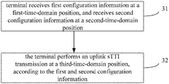
- the uplink transmission method provided by the embodiment of the application includes the following blocks.
- a terminal receives first configuration information at a first-time-domain position, and receives second configuration information at a second-time-domain position.
- the first configuration information is configured to indicate frequency-domain resource information of the terminal, when the terminal performs an uplink sTTI transmission at a third-time-domain position.
- the second configuration information is configured to indicate scheduling information of the terminal, when the terminal performs an uplink sTTI transmission at a third-time-domain position.
- the frequency-domain resource information generally includes size, and/or, position of frequency-domain resources for use in the uplink sTTI transmission.
- the size of the frequency-domain resources may be denoted with number of subcarriers, or number of Resource Blocks (RBs), or other predefined frequency-domain resource allocating units.
- the position of the frequency-domain resource may be denoted with a relative or an absolute frequency-domain position.
- the terminal performs the uplink sTTI transmission at the third-time-domain position, according to the first configuration information and the second configuration information.
- the first and second configuration information is generally related information, which is transmitted by a network side device, e.g., a base station, to a terminal.
- a network side device e.g., a base station
- the uplink sTTI transmission of the terminal at the third-time-domain position is achieved, according to the received first and second configuration information.
- the first-time-domain position may be a predefined time-domain position.
- the first-time-domain position may be a traditional control area of each subframe or some subframes, that is, the first N OFDM symbols of one subframe.
- first indication information indicating the third-time-domain position may be carried by the first configuration information.
- the first indication information may be offset information of the third-time-domain position, compared with the first-time-domain position.
- the first indication information may be an offset value of the third-time-domain position, compared with a subframe, an OFDM symbol or a sTTI of the first-time-domain position.
- the first configuration information may indicate that, the subframe offset value of the third-time-position position compared with the first-time-domain position is k.
- the terminal may determine that the third-time-domain position of is subframe (n+k).
- the first indication information may also be absolute time-domain position information of the third-time-domain position.
- the first indication information may directly indicate a subframe number, an OFDM symbol number, or a sTTI number of the third-time-domain position.
- Each of foregoing various numbers may be a value, or a value range, e.g., may indicate one subframe, or numbers of multiple subframe, or may indicate numbers of multiple OFDM symbols or numbers of multiple sTTIs.
- the terminal may receive the first configuration information, by using predetermined time-domain resources at the first-time-domain position.
- the terminal may receive the first configuration information at the first-time-domain position, which is transmitted by broadcast message.
- the terminal may receive the first configuration information at the first-time-domain position, which is transmitted by high-level signaling.
- the terminal may detect a downlink control channel at the first-time-domain position, and obtain the first configuration information from the downlink control channel.
- the downlink control channel may correspond to the uplink sTTI transmission.
- transmission in the downlink control channel may be achieved, by using Downlink Control Information (DCI) format.
- DCI Downlink Control Information
- transmission of the downlink control channel is within common search space, or dedicated search space of the terminal.
- receiving the second configuration information at the second-time-domain position may be different, accompanying with specific transmission scenes of the uplink sTTI.
- the uplink sTTI transmission includes sPUSCH
- a first downlink control channel with uplink DCI format is detected at the second-time-domain position
- the second configuration information is obtained from the first downlink control channel.
- the second configuration information may include at least one of: Modulation and Coding Scheme (MCS), sTTI length, time-domain position information, Transmission Power Control (TPC) information, precoding information, frequency hopping information, New Data indicator (NDI) information, Demodulation Reference Signal (DMRS) cyclic shift information, UL index information, Channel Quality Indicator (CQI) request information, scheduling delay information, and so on.
- MCS Modulation and Coding Scheme
- TPC Transmission Power Control
- NDI New Data indicator
- DMRS Demodulation Reference Signal
- CQI Channel Quality Indicator
- the uplink sTTI transmission includes sPUCCH
- a second downlink control channel with a downlink DCI format is detected at the second-time-domain position, and the second configuration information is obtained from the second downlink control channel.
- the second configuration information may include at least one of: code rate, sTTI length, time-domain position information, TPC information, DMRS cyclic shift information, Orthogonal sequence index information, feedback delay information, and so on.
- the second-time-domain position corresponding to the sPUCCH and the second-time-domain position corresponding to the sPUSCH may be the same, or may be different.
- the second-time-domain position may be a time-domain position, which is determined by scheduling timing, or feedback timing.
- the second-time-domain position is a time-domain position, which is determined by scheduling timing.
- a downlink control channel with uplink DCI format transmitted in subframe n or sTTI is predefined, and sPUSCH transmitted at the time-domain position of (n+k) or (n+k+m) is scheduled, in which k may be a predefined value, and m may be a value informed by foregoing downlink control channel.
- a time-domain position relationship between the second-time-domain position and the third-time-domain position may be further determined.
- a time-domain position relationship of a sTTI transmission between the second-time-domain position and the third-time-domain position is determined.
- values of k and m respectively defined for sPUSCH and sPUCCH may be the same, or may be different.
- the time template illustrated in FIG. 4 is defined.
- the time template is configured to measure stable output power, and so on.
- the transient period of the time template is a hopping adjustment period, which is made by the terminal component due to changes of power and resources. The power is not stable within such period, which is not taken as measurement contents.
- the main reason for existence of the transient period is as follows. Two adjacent transmission power change, or frequency-domain position/size of frequency-domain resource changes.
- FIG. 4 illustrates a definition for transient period between a subframe and a time slot in the existing LTE system.
- FIG. 5 illustrates a definition for transient period between an uplink channel and SRS in the LTE system, when there is no transmission for a next subframe.
- FIG. 6 illustrates a definition for transient period between an uplink channel and SRS in the LTE system, when there is a transmission for a next subframe.
- the existing channel transmission is defined by taking a subframe as a unit.
- multiple sPUCCH/sPUSCH transmissions may exist in one subframe. If frequency-domain resource position/size of each sPUCCH/sPUSCH transmission is different, it is unable to work according to the time template defined by the existing 3GPP 36.101 protocol.
- the third-time-domain position includes multiple uplink sTTIs, the frequency-domain resources of each uplink sTTI at the third-time-domain position are the same, so as to reuse the time template defined by existing 3GPP 36.101 protocol to work as much as possible, and reduce introduction of definition about a new transient period.
- the uplink transmission method provided by the embodiment of the application includes the following blocks.
- a network side device transmits first configuration information to a terminal at a first-time-domain position, and transmits second configuration information to the terminal at a second-time-domain position.
- the first configuration information is configured to indicate frequency-domain resource information of uplink sTTI transmission, which is performed by the terminal at a third-time-domain position.
- the second configuration information is configured to indicate scheduling information of the uplink sTTI transmission, which is performed by the terminal at the third-time-position position.
- the frequency-domain resource information generally includes size, and/or, position of frequency-domain resources, which are for use in the uplink sTTI transmission.
- the network side device may be a base station, or a transmission point, or other network side device.
- the frequency-domain resource information includes size, and/or, position of frequency-domain resources.
- the network side device receives the uplink sTTI transmission at the third-time-domain position, according to the first and second configuration information.
- the network side informs the terminal side of the first and second configuration information, such that the terminal may transmit the uplink sTTI at the third-time-domain position, according to the first and second configuration information.
- the network side may receive the uplink sTTI at the third-time-domain position.
- the first-time-domain position may be a predefined time-domain position.
- the first-time-domain position may be a traditional control area of each subframe or some subframes, that is, the first N OFDM symbols of one subframe.
- the third-time-domain position there may be a predefined relative position relationship between the first-time-domain position and the third-time-domain position.
- the first-time-domain position is predetermined to be subframe n
- the third-time-domain position is subframe (n+k).
- the network side device may enable the first configuration information to carry first indication information, which is for use in indicating the third-time-domain position.
- the first indication information may be offset information of the third-time-domain position, compared with the first-time-domain position.
- the first indication information may indicate an offset value of the third-time-domain position, compared with the subframe, OFDM symbol or sTTI of the first-time-domain position.
- the first configuration information may indicate that the subframe offset value of the third-time-domain position compared with the first-time-domain position is k.
- the terminal may determine that the third-time-domain position is subframe (n+k).
- the first indication information may also be absolute time-domain position information of the third-time-domain position.
- the first indication information may directly indicate a subframe number, an OFDM symbol number, or a sTTI number.
- Each of foregoing number may be a value, or a value range, e.g., indicate one subframe number or multiple subframe numbers, indicate multiple OFDM symbol numbers, or multiple sTTI numbers.
- the network side device transmits the first configuration information to the terminal, by using predetermined frequency-domain resources of the first-time-domain position.
- the network side device transmits the first configuration information via a broadcast message at the first-time-domain position.
- the network side device transmits the first configuration information via high-level signaling at the first-time-domain position.
- the network side device transmits the first configuration information via a downlink control channel of the first-time-domain position.
- the downlink control channel corresponds to the uplink sTTI transmission.
- transmission of the downlink control channel adopts an uplink DCI format.
- the downlink control channel is transmitted within common search space, or dedicated search space of the terminal.
- transmitting the second configuration information to the terminal at the second-time-domain position is different, accompanying with specific transmission scenes of the uplink sTTI.
- the network side network transmits the second configuration information via a first downlink control channel with an uplink DCI format at the second-time-domain position.
- the second configuration information may include at least one of: MCS, sTTI length, time-domain position information, TPC information, precoding information, frequency hopping information, NDI information, DMRS cyclic shift information, UL index information, DAI information, CQI request information, scheduling delay information, and so on.
- the network side device transmits the second configuration information, by using a second downlink control channel with a downlink DCI format at the second-time-domain position.
- the second configuration information may include at least one of: code rate, sTTI length, time-domain position information, TPC information, DMRS cyclic shift information, orthogonal sequence index information, feedback delay information, and so on.
- the second-time-domain position corresponding to sPUCCH may be the same as, or different from the second-time-domain position corresponding to sPUSCH.
- the second-time-domain position may be determined by scheduling timing, or feedback timing.
- the second-time-sequence position is determined by the scheduling timing.
- a downlink control channel with an uplink DCI format is predefined, the downlink control channel is transmitted within a subframe n, or within an sTTI, sPUSCH transmitted at the time-domain position of (n+k) or (n+k+m) is scheduled, in which k may be a predetermined value, m may be a value informed by foregoing downlink control channel, so as to further determine a time-domain position relationship between the second-time-domain position and the third-time-domain position, or determine a time-domain position relationship of an sTTI transmission, which is between the second-time-domain position and the third-time-position position.
- the second-time-domain position is determined by the feedback timing.
- ACK/NACK feedback information of a downlink transmission including SPDCH and a downlink control channel indicating downlink SPS resource release
- k may be a predefined value
- m may be a value informed by foregoing downlink control channel.
- a time-domain position relationship between the second-time-domain position and the third-time-domain position is determined.
- the time-domain-position relationship of an sTTI transmission between the second-time-domain position and the third-time-domain position is determined.
- k and m respectively defined for sPUSCH and sPUCCH may be the same, or may be different.
- frequency-domain resources of each uplink sTTI at the third-time-domain position are the same.
- An embodiment of the application also provides a related device, which is capable of implementing foregoing method.
- the embodiment of the application also provides a terminal, including the following units.
- a receiving unit 81 is configured to receive first configuration information at a first-time-domain position, and receive second configuration information at a second-time-domain position.
- the first configuration information is configured to indicate frequency-domain resource information, which is for use in an uplink sTTI transmission performed by the terminal at a third-time-domain position.
- the second configuration information is configured to indicate scheduling information, which is for use in the uplink sTTI transmission performed by the terminal at the third-time-domain position.
- An uplink transmitting unit 82 is configured to perform the uplink sTTI transmission at the third-time-domain position, according to the first and second configuration information.
- the receiving unit includes a first receiving subunit.
- the first receiving subunit is configured to receive the first configuration information, by using predetermined frequency-domain resources at the first-time-domain position.
- the receiving unit includes a second receiving subunit.
- the second receiving subunit is configured to receive the first configuration information via a broadcast message at the first-time-domain position, or receive the first configuration information via high-level signaling at the first-time-domain position, or detect a downlink control channel at the first-time-domain position, and obtain the first configuration information from the downlink control channel.
- the downlink control channel corresponds to the uplink sTTI transmission.
- the downlink control channel is transmitted by using the uplink DCI format.
- the downlink control channel is transmitted within common search space, or dedicated search space of the terminal.
- the receiving unit includes a third receiving subunit.
- the third receiving subunit is configured to detect a first downlink control channel with the uplink DCI format at the second-time-domain position, and obtain the second configuration information from the first downlink control channel.
- the second configuration information may include at least one of: MCS, sTTI length, time-domain position information, TPC information, precoding information, frequency hopping information, NDI information, DMRS cyclic shift information, UL index information, DAI information, CQI request information, scheduling delay information, and so on.
- the receiving unit includes a fourth receiving subunit.
- the fourth receiving subunit is configured to detect a second downlink control channel with a downlink DCI format at the second-time-domain position, and obtain the second configuration information from the second downlink control channel.
- the second configuration information may include at least one of: code rate, sTTI length, time-domain position information, TPC information, DMRS cyclic shift information, orthogonal sequence index information, feedback delay information, and so on.
- the second-time-domain position corresponding to the sPUCCH and the second-time-domain position corresponding to the sPUSCH may be the same, or may be different.
- the second-time-domain position may be determined by the scheduling timing, or feedback timing.
- an embodiment of the application provides another structure of a terminal, including the following components.
- a first transceiver 901 is configured to receive and transmit data under the control of a first processor 904 . Specifically, the first transceiver 901 may receive first configuration information at a first-time-domain position, and receive second configuration information at a second-time-domain position.
- the first processor 904 is configured to read programs in a first memory 905 , and execute the following processes:
- the first processor 904 may perform the uplink sTTI transmission, by using the first transceiver 901 and first antenna 902 .
- a bus architecture (denoted with first bus 900 ) may include an arbitrary number of interconnected bus and bridge.
- the first bus 900 may connect various circuits of one or more processors and a memory, in which the one or more processors are denoted with the first processor 904 , and the memory is denoted with the first memory 905 .
- the first bus 900 may connect various other circuits, such as, peripheral equipment, voltage regulator and power management circuit, which is known to persons having ordinary skill in the art and is not repeated here.
- a first bus interface 903 provides an interface between the first bus 900 and the first transceiver 901 .
- the first transceiver 901 may be one component, or multiple components, e.g., multiple transmitters and receivers, which provides units for communicating with various other devices on a transmission medium.
- the data processed by the first processor 904 is transmitted via a wireless medium, by using the first transceiver 901 and first antenna 902 .
- the first antenna 902 is further configured to receive the data, and transmit the data to the first processor 904 via the first transceiver 901 .
- the first processor 904 takes charge of managing the first bus 900 , performing general processes, and providing various functions, including timing, peripheral interface, voltage regulation, power management and other control functions.
- the first memory 905 may store data, which is used by the first processor 904 when executing operations.
- the first processor 904 may be a Central Processing Unit (CPU), Application Specific Integrated Circuit (ASIC), Field-Programmable Gate Array (FPGA) or Complex Programmable Logic Device (CPLD).
- CPU Central Processing Unit
- ASIC Application Specific Integrated Circuit
- FPGA Field-Programmable Gate Array
- CPLD Complex Programmable Logic Device
- the first transceiver 901 may receive the first configuration information, by using predetermined frequency-domain resources at the first-time-domain position.
- the first transceiver 901 may receive the first configuration information via a broadcast message at the first-time-domain position; or receive the first configuration information via high-level signaling at the first-time-domain position; or, detect a downlink control channel at the first-time-domain position, and obtain the first configuration information from the downlink control channel.
- the downlink control channel corresponds to the uplink sTTI transmission.
- the downlink control channel is transmitted by using an uplink DCI format.
- the downlink control channel is transmitted within common search space, or dedicated search space of the terminal.
- the first transceiver 901 is further configured to detect a first downlink control channel with the uplink DCI format at the second-time-domain position, and obtain the second configuration information from the first downlink control channel.
- the first transceiver 901 is further configured to detect a second downlink control channel with a downlink DCI format at the second-time-domain position, and obtain the second configuration information from the second downlink control channel.
- an embodiment of the application also provides a network side device, which may be a base station, or an AP, or another device.
- the network side device includes the following units.
- a transmitting unit 101 is configured to transmit first configuration information to a terminal at a first-time-domain position, and transmit second configuration information to the terminal at a second-time-domain position.
- the first configuration information is configured to indicate frequency-domain resource information, which is for use in an uplink sTTI transmission performed by the terminal at a third-time-domain position.
- the second configuration information is configured to indicate scheduling information, which is for use in the uplink sTTI transmission performed by the terminal at the third-time-domain position.
- a receiving unit 102 is configured to receive the uplink sTTI transmission at the third-time-domain position, according to the first and second configuration information.
- the transmitting unit includes a first transmitting subunit.
- the first transmitting subunit is configured to transmit the first configuration to the terminal, by using predetermined frequency-domain resources at the first-time-domain position.
- the transmitting unit includes a second transmitting subunit.
- the second transmitting subunit is configured to transmit the first configuration information, by using a broadcast message at the first-time-domain position, or transmit the first configuration information, by using high-level signaling at the first-time-domain position, or transmit the first configuration information, by using a downlink control channel at the first-time-domain position.
- the downlink control channel corresponds to the uplink sTTI transmission.
- the downlink control channel is transmitted, by using an uplink DCI format.
- the downlink control channel is transmitted within common search space, or dedicated search space of the terminal.
- the uplink sTTI transmission includes sPUSCH.
- the transmitting unit includes a third transmitting subunit.
- the third transmitting subunit is configured to transmit the second configuration information, by using a first downlink control channel with the uplink DCI format at the second-time-domain position.
- the uplink sTTI transmission includes sPUCCH.
- the transmitting unit includes a fourth transmitting subunit.
- the fourth transmitting subunit is configured to transmit the second configuration information, by using a second downlink control channel with a downlink DCI format at the second-time-domain position.
- an embodiment of the application provides another structure of a network side device, including the following components.
- a first transceiver 111 is configured to receive and transmit data under the control of a first processor 114 . Specifically, the first transceiver 111 is further configured to transmit first configuration information to a terminal at a first-time-domain position, and transmit second configuration information to the terminal at a second-time-domain position.
- a first processor 114 is configured to read programs in a first memory 115 , and execute the following processes:
- reception of the uplink sTTI transmission may be achieved, by using the first transceiver 111 and first antenna 112 .
- a bus architecture (denoted with first bus 110 ) may include an arbitrary number of interconnected bus and bridge.
- the first bus 110 connect various circuits of one or more processors and a memory, in which the one or more processors are denoted with the first processor 113 , and the memory is denoted with the first memory 115 .
- the first bus 110 may also connect various other circuits, such as peripheral equipment, voltage regulator and power management circuit. The foregoing is known to persons having ordinary skill in the art, which is not repeated here.
- a first bus interface 113 provides an interface between the first bus 110 and the first transceiver 111 .
- the first transceiver 111 may be one component, or multiple components, e.g., multiple receivers and transmitters, which provide units for communicating with various other devices on a transmission medium.
- the data processed by the first processor 114 is transmitted on a wireless medium, by using the first transceiver 111 and first antenna 112 .
- the first antenna 112 is configured to receive the data, and transmit the data to the first processor 114 via the first transceiver 111 .
- the first processor 114 takes charge of managing the first bus 110 , general processes, and providing various functions, including: timing, peripheral interface, voltage regulation, power management and other control functions.
- the first memory 115 is configured to store data, which is used by the first processor 114 when executing operations.
- the first processor 114 may be CPU, ASIC, FPGA and CPLD.
- the first transceiver 111 may transmit the first configuration information to the terminal, by using predetermined frequency-domain resources at the first-time-domain position.
- the first transceiver 111 may transmit the first configuration information, by using a broadcast message at the first-time-domain position; or, transmit the first configuration information, by using high-level signaling at the first-time-domain position; or transmit the first configuration information, by using a downlink control channel at the first-time-domain position.
- the downlink control channel corresponds to the uplink sTTI transmission.
- the downlink control channel is transmitted by using an uplink DCI format.
- the downlink control channel is transmitted within common search space, or dedicated search space of the terminal.
- the first transceiver 111 is further configured to transmit the second configuration information, by using a first downlink control channel with the uplink DCI format at the second-time-domain position.
- the first transceiver 111 is further configured to transmit the second configuration information, by using a second downlink control channel with a downlink DCI format at the second-time-domain position.
- Embodiment 1 as shown in FIG. 12 , taking sTTI transmission with four symbols as an example, assume that one subframe includes 4 sTTI transmissions, each sTTI is sPUSCH transmission, specific process is as follows.
- the terminal obtains frequency-domain resources from information carried by the downlink control channel, in which the frequency-domain resources are for use in transmitting sPUSCH by the terminal in subframe n.
- the frequency-domain resources indicated by the downlink control channel are RB 1 ⁇ 3 (other indicated units of frequency-domain resources are not excluded, e.g., subcarrier, or other predetermined frequency-domain resource allocating unit), subsequently it means that the frequency-domain resources of uplink transmission of the terminal in subframe n are RB1 ⁇ 3.
- Mode 1 the terminal detects scheduling information of sPUSCH-1 in search space of time-domain position of the first sTTI for scheduling subframe n, according to predefined scheduling sequence of sPUSCH. That is, the terminal detects a downlink control channel with an uplink DCI format.
- the time-domain position may be sTTI of nsTTI-a, or may be a certain sTTI within subframe (n-m), or may be a traditional control area of subframe (n-m), in which nsTTI is the number of sTTI located by sPUSCH1, a is the predefined scheduling sequence.
- Transmission information of sPUSCH-1 is determined by scheduling information carried by the detected downlink control channel. According to the transmission information, sPUSCH-1 is transmitted on RB1 ⁇ 3 within the first sTTI of subframe n, that is, the sTTI with the number of nsTTI.
- mode 2 the terminal detects a downlink control channel (e.g., the first sTTI within subframe n, e.g., traditional control area of each subframe before the sTTI with number nsTTI, and/or, a downlink control channel with the uplink DCI format adopted by blind detection in the search space of each sTTI) with the uplink DCI format, in the search space of traditional control area of each downlink subframe, and/or, search space of sTTI.
- a downlink control channel e.g., the first sTTI within subframe n, e.g., traditional control area of each subframe before the sTTI with number nsTTI, and/or, a downlink control channel with the uplink DCI format adopted by blind detection in the search space of each sTTI
- the terminal When detecting such downlink control channel, the terminal determines a time-domain position located by the sTTI transmission, which is scheduled by the downlink control channel, according to the time-domain position indicated by the scheduling information carried by the downlink control channel, so as to detect the first sTTI of subframe n, that is, the scheduling information of sPUSCH-1 transmitted in sTTI with number nsTTI.
- the terminal determines transmission information of sPUSCH-1, e.g., MCS, TPC, NDI, according to scheduling information carried by the detected downlink control channel.
- sPUSCH-1 is transmitted on RB1 ⁇ 3 within the first sTTI of subframe n, that is, the sTTI with number nsTTI.
- the terminal may obtain scheduling information of sPUSCH-i, which is transmitted in i th sTTI of subframe n, that is, the sTTI with number nsTTI+i ⁇ 1.
- the terminal determines transmission information of sPUSCH-i, e.g., MCS, TPC, NDI, according to the scheduling information carried by the detected downlink control channel.
- each frequency-domain resource for transmitting sPUSCH in the manner of TDM is the same, in which the sPUSCH is transmitted in 4 time domains of subframe n, so as to avoid defining transient period between sPUSCHs.
- Embodiment 2 as shown in FIG. 13 , taking sTTI transmission with four symbols as an example, assume that one subframe includes 4 sTTI transmissions, the first three sTTI transmissions are sPUSCH transmissions, the last sTTI transmission is sPUCCH transmission, specific process is as follows.
- a downlink control channel determines search space according to interleaved transmission scheme of traditional PDCCH, and detects the search space
- the terminal obtains frequency-domain resources for transmitting sPUSCH by the terminal in subframe n, by using information carried by the downlink control channel, e.g., the frequency-domain resources indicated by the downlink control channel are RB1 ⁇ 3 (other units indicated by the frequency-domain resources are not excluded, e.g., subcarrier, or other predetermined frequency-domain resources allocating units), it means that the frequency-domain resources for uplink transmission of the terminal in subframe n are RB1 ⁇ 3.
- the terminal obtains the i th sTTI of subframe n, according to the first or second method in the first embodiment, that is, obtains the scheduling information of sPUSCH-i transmitted in the sTTI with number nsTTI+i ⁇ 1.
- the terminal detects a downlink control channel with a downlink DCI format, in search space of a traditional control area of each downlink subframe, and/or, in search space of sTTI.
- Mode 1 the terminal determines a downlink subframe, and/or, sTTI, which performs ACK/NACK feedback in sPUCCH, according to predefined ACK/NACK feedback sequence, in which the sPUCCH is in the fourth sTTI of subframe n, that is, the sTTI with number nsTTI+3, and nsTTI is the number of sTTI located by sPUSCH1.
- the terminal determines transmission information of sPUCCH-1, e.g., code rate, TPC, according to indication information carried by the downlink control channel with downlink DCI format, in which the downlink control channel is detected within these downlink subframes, and/or, sTTI. According to the transmission information, the terminal transmits sPUCCH-1 on RB1 ⁇ 3 of the fourth sTTI in subframe n, that is, the sTTI with number nsTTI+3.
- Mode 2 the terminal determines a time-domain position located by the ACK/NACK feedback, according to indication information feeding back time-domain position, in which the indication information is carried by detected downlink control channel with downlink DCI format.
- the terminal determines indication information fed back by ACK/NACK in sPUCCH of the fourth sTTI in subframe n, that is, the sTTI with number nsTTI+3.
- the terminal determines transmission information of sPUCCH-1, e.g., code rate, TPC, according to the indication information carried by a downlink control channel with downlink DCI format, in which the downlink control channel is detected within a downlink subframe and/or sTTI.
- the terminal transmits sPUCCH-1 on RB1 ⁇ 3 in the fourth sTTI of subframe n, that is, the sTTI with number nsTTI+3.
- an sTTI transmission of 4 symbols is taken as an example, which is similar for sTTI transmission with other symbol length.
- sTTI transmissions with different symbol lengths may exist simultaneously, in the manner of TDM, e.g., a first sTTI transmission possesses a two-symbol length, a second sTTI transmission possesses a four-symbol length, a third sTTI transmission possesses a seven-symbol length, and so on. Processing procedure thereof is similar to foregoing process, which is not repeated here.
- sharing the same DMRS by multiple sTTIs in the manner of comb is taken as DMRS design of an uplink transmission.
- Implementation of the application is not affected by other DMRS designs of uplink transmission.
- time-domain position 1 is traditional control area of subframe (n-k).
- a relative time-domain position of time-domain position 1 and time-domain position 3 is fixed.
- processing procedure is similar, which is not repeated here.
- processing procedure of each sPUCCH is similar to the process of sPUCCH-1 in the second example, which is not repeated here.
- an uplink sTTI transmission is implemented, after configuring indication.
- size/position of frequency-domain resources of multiple sPUCCH/sPUSCH transmitted within the same subframe is fixed, so as to reuse the time template defined in the related technologies, and avoid introduction of transient period between sTTIs.
Landscapes
- Engineering & Computer Science (AREA)
- Computer Networks & Wireless Communication (AREA)
- Signal Processing (AREA)
- Quality & Reliability (AREA)
- Mobile Radio Communication Systems (AREA)
Abstract
Description
Claims (17)
Applications Claiming Priority (3)
| Application Number | Priority Date | Filing Date | Title |
|---|---|---|---|
| CN201610652031.4 | 2016-08-10 | ||
| CN201610652031.4A CN107734650B (en) | 2016-08-10 | 2016-08-10 | Uplink transmission method, network side equipment and terminal |
| PCT/CN2017/095921 WO2018028510A1 (en) | 2016-08-10 | 2017-08-04 | Uplink transmission method, network side device and terminal |
Publications (2)
| Publication Number | Publication Date |
|---|---|
| US20190191435A1 US20190191435A1 (en) | 2019-06-20 |
| US11368951B2 true US11368951B2 (en) | 2022-06-21 |
Family
ID=61161638
Family Applications (1)
| Application Number | Title | Priority Date | Filing Date |
|---|---|---|---|
| US16/324,543 Active 2037-09-15 US11368951B2 (en) | 2016-08-10 | 2017-08-04 | Uplink transmission method, network side device and terminal |
Country Status (4)
| Country | Link |
|---|---|
| US (1) | US11368951B2 (en) |
| EP (1) | EP3500007B1 (en) |
| CN (1) | CN107734650B (en) |
| WO (1) | WO2018028510A1 (en) |
Families Citing this family (10)
| Publication number | Priority date | Publication date | Assignee | Title |
|---|---|---|---|---|
| CN107231217B (en) * | 2016-03-25 | 2020-08-07 | 电信科学技术研究院 | Transmission method and device of feedback information |
| WO2018085118A1 (en) * | 2016-11-01 | 2018-05-11 | Intel IP Corporation | Downlink control information design with shorter tti |
| EP3735082B1 (en) * | 2018-02-28 | 2023-04-05 | Huawei Technologies Co., Ltd. | Downlink transmission resource allocation method and device |
| US10757656B2 (en) * | 2018-04-05 | 2020-08-25 | Qualcomm Incorporated | Loop index and time gap for group power control |
| CN110662298B (en) * | 2018-06-29 | 2021-03-23 | 维沃移动通信有限公司 | Uplink signal transmission method and terminal |
| EP4583449A3 (en) * | 2018-07-17 | 2025-07-30 | ZTE Corporation | Methods, apparatus and systems for transmitting signal and channel information |
| CN110536425A (en) * | 2018-08-09 | 2019-12-03 | 中兴通讯股份有限公司 | Information transmission method, base station, terminal, communication system, equipment, storage medium |
| JP2020047983A (en) | 2018-09-14 | 2020-03-26 | シャープ株式会社 | Base station device, terminal device, and communication method |
| CN114208248B (en) * | 2019-08-14 | 2024-09-17 | 株式会社Ntt都科摩 | Terminal and communication method |
| WO2021164544A1 (en) * | 2020-02-17 | 2021-08-26 | Guangdong Oppo Mobile Telecommunications Corp., Ltd. | Communication method and apparatus, ue and network device |
Citations (9)
| Publication number | Priority date | Publication date | Assignee | Title |
|---|---|---|---|---|
| CN101141166A (en) | 2006-09-08 | 2008-03-12 | 华为技术有限公司 | Data sending device |
| WO2009055577A1 (en) | 2007-10-25 | 2009-04-30 | Interdigital Patent Holdings, Inc. | Selecting transmission parameters for contention-based access in wireless systems |
| US7751363B1 (en) | 2004-11-22 | 2010-07-06 | Nextel Communications Inc. | System and method for allocating traffic and associated control channels |
| CN102447538A (en) | 2011-11-16 | 2012-05-09 | 中兴通讯股份有限公司 | Downlink control information transmission method and system |
| CN104468030A (en) | 2014-08-26 | 2015-03-25 | 上海华为技术有限公司 | Data transmission method, user equipment and base station |
| CN105827385A (en) | 2016-06-01 | 2016-08-03 | 珠海市魅族科技有限公司 | Time delay control method and system |
| EP3252981A2 (en) | 2016-05-12 | 2017-12-06 | ASUSTek Computer Inc. | Method and apparatus for improving control channel structure in shortened transmission time intervals in a wireless communication system |
| US20180242347A1 (en) * | 2016-05-13 | 2018-08-23 | Telefonaktiebolaget Lm Ericsson (Publ) | Configuration of uplink transmission for a wireless device |
| US20190110332A1 (en) * | 2016-04-01 | 2019-04-11 | Telefonaktiebolaget Lm Ericsson (Publ) | Wireless Communications |
-
2016
- 2016-08-10 CN CN201610652031.4A patent/CN107734650B/en active Active
-
2017
- 2017-08-04 EP EP17838640.5A patent/EP3500007B1/en active Active
- 2017-08-04 US US16/324,543 patent/US11368951B2/en active Active
- 2017-08-04 WO PCT/CN2017/095921 patent/WO2018028510A1/en not_active Ceased
Patent Citations (11)
| Publication number | Priority date | Publication date | Assignee | Title |
|---|---|---|---|---|
| US7751363B1 (en) | 2004-11-22 | 2010-07-06 | Nextel Communications Inc. | System and method for allocating traffic and associated control channels |
| CN101141166A (en) | 2006-09-08 | 2008-03-12 | 华为技术有限公司 | Data sending device |
| WO2009055577A1 (en) | 2007-10-25 | 2009-04-30 | Interdigital Patent Holdings, Inc. | Selecting transmission parameters for contention-based access in wireless systems |
| US20090109937A1 (en) | 2007-10-25 | 2009-04-30 | Interdigital Patent Holdings, Inc. | Selecting transmission parameters for contention-based access in wireless systems |
| CN102447538A (en) | 2011-11-16 | 2012-05-09 | 中兴通讯股份有限公司 | Downlink control information transmission method and system |
| CN104468030A (en) | 2014-08-26 | 2015-03-25 | 上海华为技术有限公司 | Data transmission method, user equipment and base station |
| US20170164363A1 (en) | 2014-08-26 | 2017-06-08 | Huawei Technologies Co., Ltd. | Data transmission method, user equipment, and base station |
| US20190110332A1 (en) * | 2016-04-01 | 2019-04-11 | Telefonaktiebolaget Lm Ericsson (Publ) | Wireless Communications |
| EP3252981A2 (en) | 2016-05-12 | 2017-12-06 | ASUSTek Computer Inc. | Method and apparatus for improving control channel structure in shortened transmission time intervals in a wireless communication system |
| US20180242347A1 (en) * | 2016-05-13 | 2018-08-23 | Telefonaktiebolaget Lm Ericsson (Publ) | Configuration of uplink transmission for a wireless device |
| CN105827385A (en) | 2016-06-01 | 2016-08-03 | 珠海市魅族科技有限公司 | Time delay control method and system |
Non-Patent Citations (10)
| Title |
|---|
| "Design of DL DCE for short TTI", Rl-160931, 3GPP TSG RAN WG1 Meeting #84, Malta, Feb. 15-19, 2016. |
| "On design of DL control channel for shorter TTI operation", R1-163267, 3GPP TSG-RAN WG1 Meeting #84bis, Busan, South Korea, Mar. 11-15, 2016. |
| "On/Off time mask", R4-090893, 3GPP TSG-RAN4 Meeting #50, Athens, Greece, Feb. 9-13, 2009. |
| DCI design for short TTI, Rl-162588, 3GPP TSG RAN WG1 Meeting #84bis, Busan, Korea, Apr. 11-15, 2016. |
| Extended European Search Report for EP app. No. 17838640.5, dated May 31, 2019. |
| International Preliminary Report on Patentability for PCT/CN2017/095921 dated Feb. 12, 2019 and its English translation provided by WIPO. |
| International Search Report for PCT/CN2017/095921 dated Nov. 3, 2017 and its English translation provided by WIPO. |
| Office Action issued for Chinese Application No. 201610652031.4 dated Dec. 29, 2018. |
| Written Opinion for PCT/CN2017/095921 dated Nov. 3, 2017 and its English translation provided by Google Translate. |
| Written Opinion for PCT/CN2017/095921 dated Nov. 3, 2017 and its English translation provided by WIPO. |
Also Published As
| Publication number | Publication date |
|---|---|
| EP3500007B1 (en) | 2023-06-28 |
| EP3500007A1 (en) | 2019-06-19 |
| US20190191435A1 (en) | 2019-06-20 |
| CN107734650B (en) | 2020-03-06 |
| CN107734650A (en) | 2018-02-23 |
| EP3500007A4 (en) | 2019-07-03 |
| WO2018028510A1 (en) | 2018-02-15 |
Similar Documents
| Publication | Publication Date | Title |
|---|---|---|
| US11368951B2 (en) | Uplink transmission method, network side device and terminal | |
| US10397917B2 (en) | Method and arrangement for configuring CSI measurements | |
| US10574347B2 (en) | Radio frame configuration | |
| EP2995113B1 (en) | Measurements in a wireless system | |
| RU2735647C2 (en) | User terminal, a radio base station and a radio communication method | |
| EP3432636A1 (en) | User terminal and wireless communication method | |
| CN110035444B (en) | Resource determination method and device | |
| EP3952401B1 (en) | Communication method and device | |
| EP4307809B1 (en) | User terminal and wireless communication method | |
| CN115462156A (en) | Method and apparatus for dynamic downlink multi-beam operation in a wireless communication system | |
| US20180049046A1 (en) | Apparatus and method of signalling support for reduced latency operation | |
| RU2760210C2 (en) | User terminal and radio communication method | |
| CN109845205B (en) | A system and method for reducing frequency-domain signal density | |
| EP3435701A1 (en) | User terminal, wireless base station, and wireless communication method | |
| JP7179783B2 (en) | Information transmission method and device for wireless communication system | |
| WO2018028672A1 (en) | Method for configuring frame structure, network side device, and terminal | |
| EP3713172B1 (en) | User terminal and wireless communication method | |
| JP2024084844A (en) | Radio Frame Structure | |
| HK40019012B (en) | Information transmission method and apparatus for radio communication system | |
| HK40019012A (en) | Information transmission method and apparatus for radio communication system |
Legal Events
| Date | Code | Title | Description |
|---|---|---|---|
| FEPP | Fee payment procedure |
Free format text: ENTITY STATUS SET TO UNDISCOUNTED (ORIGINAL EVENT CODE: BIG.); ENTITY STATUS OF PATENT OWNER: LARGE ENTITY |
|
| AS | Assignment |
Owner name: CHINA ACADEMY OF TELECOMMUNICATIONS TECHNOLOGY, CHINA Free format text: ASSIGNMENT OF ASSIGNORS INTEREST;ASSIGNORS:GAO, XUEJUAN;PAN, XUEMING;SIGNING DATES FROM 20181211 TO 20190104;REEL/FRAME:048325/0028 Owner name: CHINA ACADEMY OF TELECOMMUNICATIONS TECHNOLOGY, CH Free format text: ASSIGNMENT OF ASSIGNORS INTEREST;ASSIGNORS:GAO, XUEJUAN;PAN, XUEMING;SIGNING DATES FROM 20181211 TO 20190104;REEL/FRAME:048325/0028 |
|
| STPP | Information on status: patent application and granting procedure in general |
Free format text: NON FINAL ACTION MAILED |
|
| STPP | Information on status: patent application and granting procedure in general |
Free format text: RESPONSE TO NON-FINAL OFFICE ACTION ENTERED AND FORWARDED TO EXAMINER |
|
| STPP | Information on status: patent application and granting procedure in general |
Free format text: FINAL REJECTION MAILED |
|
| STPP | Information on status: patent application and granting procedure in general |
Free format text: DOCKETED NEW CASE - READY FOR EXAMINATION |
|
| STPP | Information on status: patent application and granting procedure in general |
Free format text: NON FINAL ACTION MAILED |
|
| STPP | Information on status: patent application and granting procedure in general |
Free format text: FINAL REJECTION MAILED |
|
| STPP | Information on status: patent application and granting procedure in general |
Free format text: DOCKETED NEW CASE - READY FOR EXAMINATION |
|
| STPP | Information on status: patent application and granting procedure in general |
Free format text: NON FINAL ACTION MAILED |
|
| AS | Assignment |
Owner name: DATANG MOBILE COMMUNICATIONS EQUIPMENT CO., LTD., CHINA Free format text: ASSIGNMENT OF ASSIGNORS INTEREST;ASSIGNOR:CHINA ACADEMY OF TELECOMMUNICATIONS TECHNOLOGY;REEL/FRAME:056769/0920 Effective date: 20210609 |
|
| STPP | Information on status: patent application and granting procedure in general |
Free format text: RESPONSE TO NON-FINAL OFFICE ACTION ENTERED AND FORWARDED TO EXAMINER |
|
| STPP | Information on status: patent application and granting procedure in general |
Free format text: FINAL REJECTION MAILED |
|
| STPP | Information on status: patent application and granting procedure in general |
Free format text: ADVISORY ACTION MAILED |
|
| STPP | Information on status: patent application and granting procedure in general |
Free format text: DOCKETED NEW CASE - READY FOR EXAMINATION |
|
| STPP | Information on status: patent application and granting procedure in general |
Free format text: NON FINAL ACTION MAILED |
|
| STPP | Information on status: patent application and granting procedure in general |
Free format text: RESPONSE TO NON-FINAL OFFICE ACTION ENTERED AND FORWARDED TO EXAMINER |
|
| STPP | Information on status: patent application and granting procedure in general |
Free format text: NOTICE OF ALLOWANCE MAILED -- APPLICATION RECEIVED IN OFFICE OF PUBLICATIONS |
|
| STPP | Information on status: patent application and granting procedure in general |
Free format text: PUBLICATIONS -- ISSUE FEE PAYMENT VERIFIED |
|
| STCF | Information on status: patent grant |
Free format text: PATENTED CASE |
|
| MAFP | Maintenance fee payment |
Free format text: PAYMENT OF MAINTENANCE FEE, 4TH YEAR, LARGE ENTITY (ORIGINAL EVENT CODE: M1551); ENTITY STATUS OF PATENT OWNER: LARGE ENTITY Year of fee payment: 4 |