US1136866A - Positive-driving mechanism for the hands of timepieces. - Google Patents
Positive-driving mechanism for the hands of timepieces. Download PDFInfo
- Publication number
- US1136866A US1136866A US70465312A US1912704653A US1136866A US 1136866 A US1136866 A US 1136866A US 70465312 A US70465312 A US 70465312A US 1912704653 A US1912704653 A US 1912704653A US 1136866 A US1136866 A US 1136866A
- Authority
- US
- United States
- Prior art keywords
- pinion
- setting
- hands
- hand
- center
- Prior art date
- Legal status (The legal status is an assumption and is not a legal conclusion. Google has not performed a legal analysis and makes no representation as to the accuracy of the status listed.)
- Expired - Lifetime
Links
- 230000007246 mechanism Effects 0.000 title description 13
- 238000004804 winding Methods 0.000 description 9
- 210000002832 shoulder Anatomy 0.000 description 4
- 238000010276 construction Methods 0.000 description 2
- 230000004048 modification Effects 0.000 description 2
- 238000012986 modification Methods 0.000 description 2
- 241000023813 Isia Species 0.000 description 1
- 235000013527 bean curd Nutrition 0.000 description 1
- 230000007547 defect Effects 0.000 description 1
- 230000000694 effects Effects 0.000 description 1
- 230000008030 elimination Effects 0.000 description 1
- 238000003379 elimination reaction Methods 0.000 description 1
- 239000004576 sand Substances 0.000 description 1
Images

Classifications
-
- G—PHYSICS
- G04—HOROLOGY
- G04B—MECHANICALLY-DRIVEN CLOCKS OR WATCHES; MECHANICAL PARTS OF CLOCKS OR WATCHES IN GENERAL; TIME PIECES USING THE POSITION OF THE SUN, MOON OR STARS
- G04B27/00—Mechanical devices for setting the time indicating means
- G04B27/02—Mechanical devices for setting the time indicating means by making use of the winding means
- G04B27/06—Mechanical devices for setting the time indicating means by making use of the winding means with rocking bar
Definitions
- My" 'nvention isfdesigned to overcome this defect by making'it impossible vfor the hands V (to slip or stick fast whilethe' movement con tinues to, ruin and it also permits setting tofu the hands independently of the I-movement by the manner-of arranging the; positive connection, which permitsit to be disconnectedat the time ofsetting-g
- a construction embodyingathe principles of myinvention is described in'idetail in the v following specification" and illustrated in the; accompanying drawings; this' embodiment" being only one, of 'many possible construc- L tions which may be madewi'thout departing 1 from the principles of the invention.
- Fig.1v 6 is ,a sectionalview T1 Lnollbiflbnmns,ionvnoxnvrlv, mssmmrsmmsassmabaor ammnn 'roorIARLEs wAc-Nnn, :oF SUFFOLK oo NTY, MASSACHUSETTS; 1
- Fig-n11 is a sectional 'view taken on. line 1l'1lof Fig- 0.
- Fig. isa sectional view on line;,1:318 ,ofFig-.,,12; Fig; 14: isyasec- 4 ,Beferringto-the drawings; 10 represents 5 the pillar'pla 'te of awatch movementrllthe a case, in which the movement vis -mounted, ⁇ 12 the pendant of the case',1andi-13'thewinding ;'and;setting; crown. y
- the pinions 26and 28 have the same numberof teeth, and lying beside and meshing with them is a pinion 32 having a sufficient width of face and'being so placed that its teeth may engage simultaneously with the teeth of both pinions 26 and 28.
- Said pinion 32 is mounted on an oscillating arm 33 so that it may be brought into and out of mesh with the other pinions. Itwill be seen that when the pinion 32 is, thus inmesh it furnishes apositive connection "between the pinions 26 and 28, making the cannon pinion in effect an integral part of the center stafi so.
- the pivoted bridge 1 7 has a hook or shoulder 34 which-engages a lug or other projection 35 on the arm'33, which lug is held against the I, projection by a spring 36 fastened'to the pillar plate and bearing again'st'the shoulder 37 on the arm.
- a spring 36 fastened'to the pillar plate and bearing again'st'the shoulder 37 on the arm.
- Figs, 8 and 9 is shown theapplication of my invention to a type of watch moveusa es m n in which thdwinaing and ⁇ g n mechanisms are connected with the stem, by
- lever 33 is such that when the clutch is in the position for winding and running, as shown in Fig. 8, the connection between the can-q" non pinion and center st'aflito theconnector p1n1on32 is made, and when the clutch is in. the position-"for setting, as shown in Fig.
- the pinions26 and28 will have a comparatively large numberof teeth, greater thanthat shown in Figs. 1 and2, and the pinionsmay.
- connection between. the hand and'center staff instead. of. being made directly between pinions concentric with the hand and center staff, may be made through, other pinions in. mesh" therewith at'a. distance therefrom, and, having a step-down; gear.
- Figs. 10Iand- 11' where 41 "represents a pinion on another arbor of the watch movement, which is driven-by the ated by a lever 33 to mesh with the cannon pinion for. setting and: to bev disconnected therefrom for winding. and running, in. essentially the same way as described in con nection with Figs. 8 andr9.
- jl tisnotsmate rial to this: embodiment of the invention but it ;may. conveniently be carried by an arm 44. swiveled on thexpivot 45 of the ;-centerwheel. at a higher speed,;the,double pinion 4:2, 6L3, represents the, step doiwnfl gearing, and'32 'the connector, pinion opr-I double pinion. and engagedzwiththe 0per-.
- the pinion 28' may be provided with sockets40 forreceptionof a tool to'be used in screwing it a on and unscrewing it :from the center staff, as shown 1n Fig. 6*,111 order to avoid danger ofinju'ring the teeth of the be fine and delicate,
- Such .pinions may be considered 1 as typical of any sort a of clutch and connector operated for the I 7' purpose, and thereforeil declare thatI; do
- clutch or connector suitable for, accomplishing the desiredend, wherever the same may. be situated.
- one such form coin: prises the provision of a face clutch-or the J like on the under side-of thesucannonpin ion, engaging'a complemental clutchpro-.
- cannon pinion mounted thereon and meshing with said hand setting wheel, a pin- Yion rigidly connected to saidcenter 'stafi and corresponding withsaid cannon pinion, a pivoted lever, a'pinion carried thereby andarranged tohmesh' vith saidcannon pinion and the pinion on said. center staff, and means connected with the setting wheel for shifting said lever;
- a time piece the combination with a hand setting Wheel, of a center stafi, a can: "non; pinion, mounted thereon and 'meshing, -with said hand setting wheel, a pivoted lever *provided with an ofifset portion, and means -connected with said lever for connecting said cannon pinion and center staff, and a,
Landscapes
- Physics & Mathematics (AREA)
- General Physics & Mathematics (AREA)
- Measurement Of Unknown Time Intervals (AREA)
Description
L. C. COLLINS. v POSITIVE DRIVING MECHANISM FOR THE HANDS 0F TIMEPIECES.
APPLICATION FILED JUNE 19, 1912.
1,136,866, Patented Apr. 20, 1915.
2 SHEETS-SHEET l.
THE NORRIS PETERS 130.. PHOTOYLITHOH WASHING TON D. l
L. C. COLLINS.
POSITIVE DRIVRNG MECHANISM FOR THE HANDS 0F TIMEPIECES.
APPLICATION FILED mm: 19, 1912.
1,136,866, Patented Apr. 20, 1915 2 SHEETS-SHEET 2.
12] 46 47 25 III/111ml 65 -7 'II/IIIIIIIIIIIIII I Imv entar: Jean 6.60 ZZi/ns rHE NORRIS PETERS c0, FHOm-LITHO.. WASHINGTON, D c. I
" hitherto "been considered necessary in 7 order i tozpermitis etting ofpthehands, is? a" cause of sented as a pocketwa'tch', and in the followv in}; specification it is described asv such this, representation and description beingigin- "tended for. the purpose of illustration only rosirrvngnnrvlne nncrianrsm ron'iniin mms'b mamgsa To all whom concern-.5 I r Berit-lmownthat I', LEON-G. CoLLIN's, a
' resident of Roxbury, in the countyof i Suffolk andfState ofi-Massachusetts,- havezins vented certain new and useful Improve 'ments in Positive-Driving; Mechanismifor the Hands of Timepieces,- of which thefol-r lowing-is-a specification. I I j I The object of he present invention-is to provide a means bywhich the'hand's of a watchor clock mayiber positively connected with the movementwith consequent elimi nation 'of fthe necessity-of a frictional connection; which has hitherto been'the mode of connectionuniversally employed in watch construction.
the, watch oriclock movement,:w hich has inaccuracy because it" frequently iinsufliciently secure and the hands are? therefore I I liable to fail'to movein exact synchronism with the mechanismfresultin'g in loss of accuracy. r
My" 'nvention isfdesigned to overcome this defect by making'it impossible vfor the hands V (to slip or stick fast whilethe' movement con tinues to, ruin and it also permits setting tofu the hands independently of the I-movement by the manner-of arranging the; positive connection, which permitsit to be disconnectedat the time ofsetting-g A construction embodyingathe principles of myinvention is described in'idetail in the v following specification" and illustrated in the; accompanying drawings; this' embodiment" being only one, of 'many possible construc- L tions which may be madewi'thout departing 1 from the principles of the invention. a a
In the drawings the "timepiece is repreand not as limiting'me in any way as to the character of {timepiece Ito which the invention may be applied.:=.
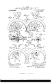
vation ofithe watch with the hands and dial a "removed, showing :the'mechanism'embodying Vmyil invention in the position for set- ,tingiFigiQ isia similar-"view showing the mechanism in'p'osition forwinding and'runv I The frictional engagement between the hands and the center staff of ning', whichisthe normal position Fig; is a deta1l; F1g.4 is an enlarged detail section on line fltofFig. 1; Fig. 5,,is an elevation of a, pinion and, sleeve connected thereto,
adapted: to carry "the minuteihand of the watch, the. same .beingcommonly known as 'acannon'ipinion; Fig.1v 6 is ,a sectionalview T1 Lnollbiflbnmns,ionvnoxnvrlv, mssmmrsmmsassmabaor ammnn 'roorIARLEs wAc-Nnn, :oF SUFFOLK oo NTY, MASSACHUSETTS; 1
sa mmfmesPatent."1: Patented Apr;2o,i915. Applicationfiledlune'l, 1 1eL-Lsei 1a1m. 704, 53. r v 7 of a pinion forming one ofthellparts of the presentinvention;Figrgfigiis a partial plan vlewof a modificationof such pinion-;;='.Fig.l* 71s an, elevation of the center, staff Wheel! ,and pinion; Figs. 8 and,9 areviewslsimilar to--Figs; 2,:andlj respectively, showing the invention .i applied to" a Watch having a )dif-i ferentjtype of "winding and setting mechanism. ,;Fig. "10 is a.= front vilewof-a watch with the 'dialflremoved, showing a modification of the driving connection for the hand I tionallview on-line'14.-14 of Fig.12.
'c'arri'en'. "Fig-n11 is a sectional 'view taken on. line 1l'1lof Fig- 0." Fi 12 iS-a front/ viewevshowijn'g another modificationa-of the I invention. Fig. isa sectional view on line;,1:318 ,ofFig-.,,12; Fig; 14: isyasec- 4 ,Beferringto-the drawings; 10 represents 5 the pillar'pla 'te of awatch movementrllthe a case, in which the movement vis -mounted,{ 12 the pendant of the case',1andi-13'thewinding ;'and;setting; crown. y
" .14: represents th'ewinding wheel connected I to the mainspring arbor 15; 16v is a setting wheeljand 17 is" a" triage oscillating upon the center- 18 and carrying idlepinions l9 and 20. meshingwith a wheel 21 whichfis driven by =thegcrown '13,: by I is it mechanism which is oldand "common and is thereforenothere shown, for either wind ing=the mainspringior settingthe hand of the watch. 5 V
which are fixed the center wheel 23 and pin-:
Referring now ,4, 22 represents i: the 'centersta-if of the watch movement, on
ion Qhthe samejbeing held in the pillar:
aWbearingfor the sleeve carrying. the hour;
neitherz thehour handgor such gearing being plate; 10. f Surrounding the center staifis ff a sleeve 25 having at oneendja bearing face I .26 on whichgis fas'tened the minute hand,"
and ,connectedat the opposite, end t'o jaj pinion 26, *said 'sleeve; and opinion together a constitutinguwhat islmown as-thecannon I pinion, Said cannon *pinionalso serves as i hand, which is drivenby the iusu'aligearing, i
loo
well-known type; Rigidly secured: to, a threaded portion 2710f thece'nter'staif is a pinion 28, which abuts against a shoulder 29 on the staff. The thread isleft-handed in order to avoid danger of 'loosening'the pinion when the staff. rotates There is a slightly greater distance between the shoul der 29 and another shoulder- 30 on the center staff, which underlies the pillar plate, than V the thickness of that part of the .plate which the journaled 31 of thestaff is contained, to provide sufficient end shake of the staff to allow it, to turn freely in its bearing. 9 v V The pinions 26and 28 have the same numberof teeth, and lying beside and meshing with them is a pinion 32 having a sufficient width of face and'being so placed that its teeth may engage simultaneously with the teeth of both pinions 26 and 28. Said pinion 32 is mounted on an oscillating arm 33 so that it may be brought into and out of mesh with the other pinions. Itwill be seen that when the pinion 32 is, thus inmesh it furnishes apositive connection "between the pinions 26 and 28, making the cannon pinion in effect an integral part of the center stafi so. that the latter are inevitably compelled to rotate in'unison and any rela: tive movement betweenthehands and watch mechanism is prevented; 'However, when the hands are to beset it is only necessaryto displace the pinion 32- far. enough to clear the pinions 26. and 28, whereupon the cannon pinion is released and the hands may be freelyturned. The movement of pinion32 fer'fthi's purpose, is accomplished by the same act whichplaces the winding andgset v ting mechanism in the position for setting.
For this purpose the pivoted bridge 1 7 has a hook or shoulder 34 which-engages a lug or other projection 35 on the arm'33, which lug is held against the I, projection by a spring 36 fastened'to the pillar plate and bearing again'st'the shoulder 37 on the arm. When the bridge 17 is in the position shown in Fig. 1', which is that for setting, connection-is made between thewheel 21' and the setting pinion '16, the other o'r-winding pinion 19 being disengaged from the winding wheel 14. At the sametime the connecting pinion 32 is held clear of the pinions 26 and 28. On the other hand, when the bridge 17 is in the position for winding, which is also the normal position for running, the connection with the setting pinion isbroken and the connecting pinion 32 is in operativ'e position, all as shown in Fig. 2. The
bridge ;may be moved into these two positions by any '01 the means hitherto used, as by end'wis'e movement of the stem or by a lever exposed at. the side of the case, or otherwisei i In Figs, 8 and 9 is shown theapplication of my invention to a type of watch moveusa es m n in which thdwinaing and {g n mechanisms are connected with the stem, by
an endwise movable clutch 38 having two sets of teeth on its opposite ends respectively; The clutch has a groove 39 which receives the part of a lever 33? carrying the pinion 32 in the same arrangement relaftively .to the pinions 26 and 28 as that." al:
ready described. The location of lever 33 is such that when the clutch is in the position for winding and running, as shown in Fig. 8, the connection between the can-q" non pinion and center st'aflito theconnector p1n1on32 is made, and when the clutch is in. the position-"for setting, as shown in Fig.
9, this connection is broken. Any of the mechanisms now in common use formoving clutches ofthe nature of the clutch 38 now in common nsemaybeemployed, andasmy invention does not I'GSIdBlIl any such mechanism, but only in the application of my hand. connector thereto, such mechanism is r not shown. a
Preferably the teeth of the pinions26,
28. and 32 are pointed in order that after setting ofthe hands the'pinion 32 may come into. proper mesh even though the :cannon pinion should'notl have been left in. aline mentvwiththe pinion 28. Preferably the pinions26 and28 will have a comparatively large numberof teeth, greater thanthat shown in Figs. 1 and2, and the pinionsmay.
also. be made. of" relatively-larger diameter. This is in'order that there may notbe any; appreciable.Idisplacement of: the hand when the connector pinion is brought into operm ation aftersetting. For the sameobjectthe connection between. the hand and'center staff, instead. of. being made directly between pinions concentric with the hand and center staff, may be made through, other pinions in. mesh" therewith at'a. distance therefrom, and, having a step-down; gear.
ratio, as shown in Figs. 10Iand- 11', where 41 "represents a pinion on another arbor of the watch movement, which is driven-by the ated by a lever 33 to mesh with the cannon pinion for. setting and: to bev disconnected therefrom for winding. and running, in. essentially the same way as described in con nection with Figs. 8 andr9. jl tisnotsmate rial: to this: embodiment of the invention but it ;may. conveniently be carried by an arm 44. swiveled on thexpivot 45 of the ;-centerwheel. at a higher speed,;the,double pinion 4:2, 6L3, represents the, step doiwnfl gearing, and'32 'the connector, pinion opr-I double pinion. and engagedzwiththe 0per-.
ating lever by' a pin andslot connection, a p1n46 on sand lever enteringa slot 47 1I1-tl18 arm. Indeed, many modifications may bemadein theconstruction and location of the connectingelements without departing .irom the spiritaof my inventiomand i 12o how the connector pinion is herev mounted,
and setting mechanism, embodying axholder.
' forthe minute hand,xsuch as a cannon "pinion, capable of moving independently of T the movement, in combination with a-po'sitive connector shiftable to i make positive driving connection between the holder and movement for winding and runnlng and tobreak the connection for setting, with- .inthe scope of my invention and is covered bythe more generic or my, appended claims. The pinion 28'; may be provided with sockets40 forreceptionof a tool to'be used in screwing it a on and unscrewing it :from the center staff, as shown 1n Fig. 6*,111 order to avoid danger ofinju'ring the teeth of the be fine and delicate,
" ing device for securing the loosely arranged hand upon a rotating stafi, and that' the pinion 32 is a connector complemental to these clutching; members-for ,makingthe connection between them.v Such .pinions may be considered 1 as typical of any sort a of clutch and connector operated for the I 7' purpose, and thereforeil declare thatI; do
" not limit my invention tothese' specific e1e- 5 ments,' but include within its scope any.
form of clutch or connector" suitable for, accomplishing the desiredend, wherever the same may. be situated. one such form coin: prises the provision of a face clutch-or the J like on the under side-of thesucannonpin ion, engaging'a complemental clutchpro-.
7 f vided on the center stafi in place of the" threaded portion '27, such as the ins 48 and a cam 7 element V iQyconnected with the setting mechanism through. the; lever 33?; and engaging an arm whichis engagedwith I the cannOnpiniOn, the arrangementbei g 1 ranged for setting, the cannon pinion islifted,
"clear of the ,complemental clutch; whereby it"may rotate independently of the center staff 50. I-Iaving described ,myinvention, what I and complemental socketsshown in ig. 13,
such that when the settingtmechanism is arclaim as newand desireto' secure by Letters'Patentis; V I
1. In a time-piece the combination with a hand setting wheel; of a center staflt; a can-' non pinion mounted thereon and meshing with saidyhand setting ,wheehr ineans for positively connecting said center staif *and 'said'c'ann0n pinion to rotate in unison at the I 1 i me peed, and meanssfor controllingsaidfi hand ng Wheel, said controllingmeans 3 being provided with means for acting on s the connectingvmeans todisconnect1said with said hand settingwheel, a pivoted 3. In a time piece the combinationwithfa v c a I i hand setting wheel, of a center stafl a caln- It will be observedpthatthe pinions '26; I and 28 constitute in efiect parts of aclut'chnon pinion mounted thereon and meshing said connecting member.
cannon pinion" mounted thereon and meshing with said hand setting wheel, a pin- Yion rigidly connected to saidcenter 'stafi and corresponding withsaid cannon pinion, a pivoted lever, a'pinion carried thereby andarranged tohmesh' vith saidcannon pinion and the pinion on said. center staff, and means connected with the setting wheel for shifting said lever;
' 5. In a; time piece the combination with a hand setting Wheel, of a center stafi, a can: "non; pinion, mounted thereon and 'meshing, -with said hand setting wheel, a pivoted lever *provided with an ofifset portion, and means -connected with said lever for connecting said cannon pinion and center staff, and a,
sigiature, in presence oftwo witnesses.
is E -1}; G. COLLINS. I I
Witnesses: a a 1 ARTHUR H;BR0WN, J. MonPi-rr.
Gopiea'ot this patent may be obtainedjtorflve cents each; by, addressing the Commissioner! intents; l 1 i Wuh1ngton,D. G.
lever, means carried by said lever, for 'connecting saidcenter, staifand said cannon pinion to rotate inunison atthe same spee'd; and controlling means connected with said *handsetting :wheel for shifting said lever. pinion, particularlyiiincasesuch teeth should with said 'hand' setting -'wheel,a member 1 rigidly connected to saidr center stafli',a mov 1 f 1 able member for connecting said cannon I pinion with the rigidmember of said 'ceniter 'stafl", and means for controlling said hand setting wheel, said controlling means I a being provided" with fmeansfor shifting In a time piece the "combination-"with" l I aQhand-setting wheel, of a center stafl", a
"movable member connectedwith said tti I a, wheel to engage the offsetportion ofjsaidj
Priority Applications (1)
| Application Number | Priority Date | Filing Date | Title |
|---|---|---|---|
| US70465312A US1136866A (en) | 1912-06-19 | 1912-06-19 | Positive-driving mechanism for the hands of timepieces. |
Applications Claiming Priority (1)
| Application Number | Priority Date | Filing Date | Title |
|---|---|---|---|
| US70465312A US1136866A (en) | 1912-06-19 | 1912-06-19 | Positive-driving mechanism for the hands of timepieces. |
Publications (1)
| Publication Number | Publication Date |
|---|---|
| US1136866A true US1136866A (en) | 1915-04-20 |
Family
ID=3204970
Family Applications (1)
| Application Number | Title | Priority Date | Filing Date |
|---|---|---|---|
| US70465312A Expired - Lifetime US1136866A (en) | 1912-06-19 | 1912-06-19 | Positive-driving mechanism for the hands of timepieces. |
Country Status (1)
| Country | Link |
|---|---|
| US (1) | US1136866A (en) |
-
1912
- 1912-06-19 US US70465312A patent/US1136866A/en not_active Expired - Lifetime
Similar Documents
| Publication | Publication Date | Title |
|---|---|---|
| US1136866A (en) | Positive-driving mechanism for the hands of timepieces. | |
| US1442249A (en) | Calendar watch | |
| US253338A (en) | audemars | |
| US3608305A (en) | Coordinated combined releasable day and date jumper mechanism for calendar timepieces | |
| US410967A (en) | School | |
| US2063884A (en) | Alarm clock | |
| US942659A (en) | Winding-indicator. | |
| US3922846A (en) | Date setting device of a calendar watch | |
| US403338A (en) | August fischer | |
| US298988A (en) | Time-piece for operating mechanical devices | |
| US801914A (en) | Dial-train for timepieces. | |
| US871019A (en) | Clock. | |
| US2105966A (en) | Watch construction | |
| US1234829A (en) | Alarm-clock. | |
| US952921A (en) | Watch. | |
| US1677790A (en) | Alarm clock | |
| US1139369A (en) | Striking, lever or marine clock. | |
| US101398A (en) | Improvement in watches | |
| US310936A (en) | Stop watch | |
| US1034141A (en) | Alarm-clock. | |
| US1283476A (en) | Watch. | |
| US1143567A (en) | Winding-indicator. | |
| US53146A (en) | Improvement in time-pieces | |
| US3129558A (en) | Indicator setting means for timepiece showing the time in two time-belts | |
| US708985A (en) | Stem-winding watch. |