US11368185B2 - Sharing frequency generator settings in networks - Google Patents
Sharing frequency generator settings in networks Download PDFInfo
- Publication number
- US11368185B2 US11368185B2 US16/922,627 US202016922627A US11368185B2 US 11368185 B2 US11368185 B2 US 11368185B2 US 202016922627 A US202016922627 A US 202016922627A US 11368185 B2 US11368185 B2 US 11368185B2
- Authority
- US
- United States
- Prior art keywords
- frequency
- message
- frequency setting
- base station
- setting
- Prior art date
- Legal status (The legal status is an assumption and is not a legal conclusion. Google has not performed a legal analysis and makes no representation as to the accuracy of the status listed.)
- Active, expires
Links
Images


Classifications
-
- H—ELECTRICITY
- H04—ELECTRIC COMMUNICATION TECHNIQUE
- H04B—TRANSMISSION
- H04B1/00—Details of transmission systems, not covered by a single one of groups H04B3/00 - H04B13/00; Details of transmission systems not characterised by the medium used for transmission
- H04B1/69—Spread spectrum techniques
- H04B1/713—Spread spectrum techniques using frequency hopping
- H04B1/7136—Arrangements for generation of hop frequencies, e.g. using a bank of frequency sources, using continuous tuning or using a transform
-
- H—ELECTRICITY
- H04—ELECTRIC COMMUNICATION TECHNIQUE
- H04B—TRANSMISSION
- H04B1/00—Details of transmission systems, not covered by a single one of groups H04B3/00 - H04B13/00; Details of transmission systems not characterised by the medium used for transmission
- H04B1/005—Details of transmission systems, not covered by a single one of groups H04B3/00 - H04B13/00; Details of transmission systems not characterised by the medium used for transmission adapting radio receivers, transmitters andtransceivers for operation on two or more bands, i.e. frequency ranges
-
- H—ELECTRICITY
- H04—ELECTRIC COMMUNICATION TECHNIQUE
- H04B—TRANSMISSION
- H04B1/00—Details of transmission systems, not covered by a single one of groups H04B3/00 - H04B13/00; Details of transmission systems not characterised by the medium used for transmission
- H04B1/38—Transceivers, i.e. devices in which transmitter and receiver form a structural unit and in which at least one part is used for functions of transmitting and receiving
- H04B1/40—Circuits
- H04B1/401—Circuits for selecting or indicating operating mode
-
- H—ELECTRICITY
- H04—ELECTRIC COMMUNICATION TECHNIQUE
- H04B—TRANSMISSION
- H04B1/00—Details of transmission systems, not covered by a single one of groups H04B3/00 - H04B13/00; Details of transmission systems not characterised by the medium used for transmission
- H04B1/69—Spread spectrum techniques
- H04B1/713—Spread spectrum techniques using frequency hopping
- H04B1/7143—Arrangements for generation of hop patterns
-
- H—ELECTRICITY
- H04—ELECTRIC COMMUNICATION TECHNIQUE
- H04B—TRANSMISSION
- H04B1/00—Details of transmission systems, not covered by a single one of groups H04B3/00 - H04B13/00; Details of transmission systems not characterised by the medium used for transmission
- H04B1/69—Spread spectrum techniques
- H04B1/713—Spread spectrum techniques using frequency hopping
- H04B1/7156—Arrangements for sequence synchronisation
-
- H—ELECTRICITY
- H04—ELECTRIC COMMUNICATION TECHNIQUE
- H04W—WIRELESS COMMUNICATION NETWORKS
- H04W72/00—Local resource management
- H04W72/04—Wireless resource allocation
- H04W72/044—Wireless resource allocation based on the type of the allocated resource
- H04W72/0453—Resources in frequency domain, e.g. a carrier in FDMA
-
- H—ELECTRICITY
- H04—ELECTRIC COMMUNICATION TECHNIQUE
- H04W—WIRELESS COMMUNICATION NETWORKS
- H04W76/00—Connection management
- H04W76/30—Connection release
- H04W76/38—Connection release triggered by timers
-
- H—ELECTRICITY
- H04—ELECTRIC COMMUNICATION TECHNIQUE
- H04B—TRANSMISSION
- H04B1/00—Details of transmission systems, not covered by a single one of groups H04B3/00 - H04B13/00; Details of transmission systems not characterised by the medium used for transmission
- H04B1/69—Spread spectrum techniques
- H04B1/713—Spread spectrum techniques using frequency hopping
- H04B1/7136—Arrangements for generation of hop frequencies, e.g. using a bank of frequency sources, using continuous tuning or using a transform
- H04B2001/71362—Arrangements for generation of hop frequencies, e.g. using a bank of frequency sources, using continuous tuning or using a transform using a bank of frequency sources
-
- H—ELECTRICITY
- H04—ELECTRIC COMMUNICATION TECHNIQUE
- H04B—TRANSMISSION
- H04B1/00—Details of transmission systems, not covered by a single one of groups H04B3/00 - H04B13/00; Details of transmission systems not characterised by the medium used for transmission
- H04B1/69—Spread spectrum techniques
- H04B1/713—Spread spectrum techniques using frequency hopping
- H04B1/7156—Arrangements for sequence synchronisation
- H04B2001/71563—Acquisition
Definitions
- aspects of the present disclosure relate generally to wireless communication systems, and more particularly, by way of example but not limitation, to frequency generator (e.g., local oscillator) settings.
- frequency generator e.g., local oscillator
- Wireless communication networks are widely deployed to provide various communication services such as voice, video, packet data, messaging, broadcast, and the like. These wireless networks may be multiple-access networks capable of supporting multiple users by sharing the available network resources. Such networks, which are usually multiple access networks, support communications for multiple users by sharing the available network resources.
- UTRAN Universal Terrestrial Radio Access Network
- the UTRAN is the radio access network (RAN) defined as a part of the Universal Mobile Telecommunications System (UMTS), a third generation (3G) mobile phone technology supported by the 3rd Generation Partnership Project (3GPP).
- UMTS Universal Mobile Telecommunications System
- 3GPP 3rd Generation Partnership Project
- Examples of multiple-access network formats include Code Division Multiple Access (CDMA) networks, Time Division Multiple Access (TDMA) networks, Frequency Division Multiple Access (FDMA) networks, Orthogonal FDMA (OFDMA) networks, and Single-Carrier FDMA (SC-FDMA) networks.
- CDMA Code Division Multiple Access
- TDMA Time Division Multiple Access
- FDMA Frequency Division Multiple Access
- OFDMA Orthogonal FDMA
- SC-FDMA Single-Carrier FDMA
- a wireless communication network may include a number of base stations or node Bs that can support communication for a number of user equipments (UEs).
- a UE may communicate with a base station via downlink and uplink.
- the downlink (or forward link) refers to the communication link from the base station to the UE
- the uplink (or reverse link) refers to the communication link from the UE to the base station.
- a base station may transmit data and control information on the downlink to a UE and/or may receive data and control information on the uplink from the UE.
- a transmission from the base station may encounter interference due to transmissions from neighbor base stations or from other wireless radio frequency (RF) transmitters.
- RF radio frequency
- a transmission from the UE may encounter interference from uplink transmissions of other UEs communicating with the neighbor base stations or from other wireless RF transmitters. This interference may degrade performance on both the downlink and uplink.
- a UE may modify a first frequency setting of a frequency generator, such as a local oscillator, to generate a second frequency setting. Modifying the first frequency setting may be performed in order to support advanced features, such as fast frequency hopping, offset zero intermediate frequency (OZIF)/low intermediate frequency (LIF) operations, shared receive/transmit carrier aggregation, and band jammer and interference reduction, as non-limiting examples, or to support co-existence in multi-radio or multiple subscription devices.
- the UE may share the second frequency setting with a base station.
- the UE may transmit a message that indicates the second frequency setting to the base station.
- the message is a UE assistance information message.
- the UE assistance information message may include an extendedRFSignalling field that indicates the second frequency setting.
- the message is a media access control (MAC) control element.
- the base station may use the second frequency setting (instead of the first frequency setting) in performing one or more operations, such as direct current (DC) cancellation or scheduling of a DC subcarrier, as non-limiting examples.
- DC direct current
- Performing such operations using the second frequency setting may improve various transmit performance metrics associated with the UE and as measured by the base station, such as error vector magnitude (EVM), adjacent channel leakage ratio (ACLR), spectrum emission mask (SEM), and/or occupied bandwidth (OBW), which may also improve metrics such as signal-to-noise ratio (SNR) and effective maximum throughput.
- EVM error vector magnitude
- ACLR adjacent channel leakage ratio
- SEM spectrum emission mask
- OBW occupied bandwidth
- SNR signal-to-noise ratio
- a method of wireless communication includes determining, by a user equipment (UE), a first frequency setting for a frequency generator of the UE.
- the first frequency setting is associated with a first frequency.
- the method includes modifying the first frequency setting to generate a second frequency setting for the frequency generator.
- the second frequency setting is associated with a second frequency that is different than the first frequency.
- the method also includes generating a message that indicates the second frequency setting.
- the method further includes transmitting the message from the UE to a base station.
- an apparatus configured for wireless communication includes means for determining a first frequency setting for a frequency generator of a user equipment (UE).
- the first frequency setting is associated with a first frequency.
- the apparatus includes means for modifying the first frequency setting to generate a second frequency setting for the frequency generator.
- the second frequency setting is associated with a second frequency that is different from the first frequency.
- the apparatus also includes means for generating a message that indicates the second frequency setting.
- the apparatus further includes means for transmitting the message to a base station.
- a non-transitory computer-readable medium having program code recorded thereon.
- the program code further includes code to determine, by a user equipment (UE), a first frequency setting for a frequency generator of the UE.
- the first frequency setting is associated with a first frequency.
- the program code also includes code to modify the first frequency setting to generate a second frequency setting for the frequency generator.
- the second frequency setting is associated with a second frequency that is different from the first frequency.
- the code includes code to generate a message that indicates the second frequency setting.
- the code further includes code to initiate transmission of the message from the UE to a base station.
- an apparatus configured for wireless communication.
- the apparatus includes at least one processor, and a memory coupled to the processor.
- the memory stores instructions that, when executed by the at least one processor, cause the at least one processor to determine, by a user equipment (UE), a first frequency setting for a frequency generator of the UE.
- the first frequency setting is associated with a first frequency.
- the instructions cause the at least one processor to modify the first frequency setting to generate a second frequency setting for the frequency generator.
- the second frequency setting is associated with a second frequency that is different from the first frequency.
- the instructions also cause the at least one processor to generate a message that indicates the second frequency setting.
- the instructions further cause the at least one processor to initiate transmission of the message from the UE to a base station.
- a method of wireless communication includes storing, at a base station, a first frequency setting for a frequency generator of a user equipment (UE), the first frequency setting associated with a first frequency.
- the method includes receiving a message at the base station from the UE.
- the message indicates a second frequency setting for the frequency generator.
- the second frequency setting is associated with a second frequency that is different from the first frequency.
- the method also includes performing, at the base station, an operation based on the second frequency setting.
- the method further includes transmitting a second message from the base station to the UE based on performance of the operation.
- an apparatus configured for wireless communication includes means for storing a first frequency setting for a frequency generator of a user equipment (UE).
- the first frequency setting is associated with a first frequency.
- the apparatus includes means for receiving a message from the UE.
- the message indicates a second frequency setting for the frequency generator.
- the second frequency setting is associated with a second frequency that is different from the first frequency.
- the apparatus also includes means for performing an operation based on the second frequency setting.
- the apparatus further includes means for transmitting a second message to the UE based on performance of the operation.
- a non-transitory computer-readable medium having program code recorded thereon.
- the program code further includes code to store, at a base station, a first frequency setting for a frequency generator of a user equipment (UE).
- the first frequency setting is associated with a first frequency.
- the program code includes code to receive a message at the base station from the UE.
- the message indicates a second frequency setting for the frequency generator.
- the second frequency setting is associated with a second frequency that is different from the first frequency.
- the program code also includes code to perform, at the base station, an operation based on the secondary frequency setting.
- the program code further includes code to initiate transmission of a second message from the base station to the UE based on performance of the operation.
- an apparatus configured for wireless communication.
- the apparatus includes at least one processor, and a memory coupled to the processor.
- the first frequency setting is associated with a first frequency.
- the instructions cause the at least one processor to receive a message at the base station from the UE.
- the message indicates a second frequency setting for the frequency generator.
- the second frequency setting is associated with a second frequency that is different from the first frequency.
- the instructions also cause the at least one processor to perform, at the base station, an operation based on the second frequency setting.
- the instructions further cause the at least one processor to initiate transmission of a second message from the base station to the UE based on performance of the operation.
- FIG. 1 is a block diagram illustrating details of a wireless communication system.
- FIG. 2 is a block diagram conceptually illustrating a design of a base station/eNB and a UE configured according to one aspect of the present disclosure.
- FIG. 3 is a block diagram illustrating an example of a wireless communications system that shares frequency settings for a frequency generator of a UE in accordance with aspects of the present disclosure
- FIGS. 4A-4B illustrate examples of frequency settings for a frequency generator in accordance with aspects of the present disclosure.
- FIGS. 5A-5B illustrate examples of media access control (MAC) control elements (CEs) for conveying frequency generator settings according to aspects of the present disclosure.
- MAC media access control
- CEs control elements
- FIG. 6 is a ladder diagram illustrating an example of sharing frequency settings for a frequency generator of a UE according to aspects of the present disclosure.
- FIG. 7 is a block diagram illustrating example blocks executed by a UE configured according to an aspect of the present disclosure.
- FIG. 8 is a block diagram illustrating example blocks executed by a base station configured according to an aspect of the present disclosure.
- FIG. 9 is a block diagram conceptually illustrating a design of a UE according to some embodiments of the present disclosure.
- FIG. 10 is a block diagram conceptually illustrating a design of a base station configured according to some embodiments of the present disclosure.
- This disclosure relates generally to providing or participating in authorized shared access between two or more wireless communications systems, also referred to as wireless communications networks.
- the systems, methods, devices, and apparatuses described herein enable communication of a frequency setting of a frequency generator at a user equipment (UE) to a base station, for use by the base station in performing one or more operations.
- UE user equipment
- frequency generators of UEs such as local oscillators
- This frequency setting is provided to the base station (e.g., during an initial connection/association), which may use the frequency setting during performance of one or more operations.
- some UEs include the capability to change the frequency setting of the local oscillator, for example to support one or more advanced features.
- the base station remains unaware of the change in the frequency setting of the local oscillator at the UE.
- the UE may transmit a message that includes an updated frequency setting to the base station.
- the message is a UE assistance information message.
- the UE assistance information message may include an extendedRFSignalling field that indicates the updated frequency setting.
- the message is a media access control (MAC) control element.
- the base station may receive and use the updated frequency setting in performing one or more operations, such as direct current (DC) cancellation or scheduling of a DC subcarrier, as non-limiting examples, to improve performance of the UE, the network, or both.
- DC direct current
- DC subcarrier a DC subcarrier
- the techniques and apparatus may be used for wireless communication networks such as code division multiple access (CDMA) networks, time division multiple access (TDMA) networks, frequency division multiple access (FDMA) networks, orthogonal FDMA (OFDMA) networks, single-carrier FDMA (SC-FDMA) networks, LTE networks, GSM networks, 5 th Generation (5G) or new radio (NR) networks (sometimes referred to as “5G NR” networks/systems/devices), as well as other communications networks.
- CDMA code division multiple access
- TDMA time division multiple access
- FDMA frequency division multiple access
- OFDMA orthogonal FDMA
- SC-FDMA single-carrier FDMA
- LTE long-term evolution
- GSM Global System for Mobile communications
- 5G 5 th Generation
- NR new radio
- a CDMA network may implement a radio technology such as universal terrestrial radio access (UTRA), cdma2000, and the like.
- UTRA includes wideband-CDMA (W-CDMA) and low chip rate (LCR).
- CDMA2000 covers IS-2000, IS-95, and IS-856 standards.
- a TDMA network may implement a radio technology such as Global System for Mobile Communications (GSM).
- GSM Global System for Mobile Communications
- 3GPP defines standards for the GSM EDGE (enhanced data rates for GSM evolution) radio access network (RAN), also denoted as GERAN.
- GERAN is the radio component of GSM/EDGE, together with the network that joins the base stations (for example, the Ater and Abis interfaces) and the base station controllers (A interfaces, etc.).
- the radio access network represents a component of a GSM network, through which phone calls and packet data are routed from and to the public switched telephone network (PSTN) and Internet to and from subscriber handsets, also known as user terminals or user equipments (UEs).
- PSTN public switched telephone network
- UEs subscriber handsets
- a mobile phone operator's network may comprise one or more GERANs, which may be coupled with UTRANs in the case of a UMTS/GSM network.
- An operator network may also include one or more LTE networks, and/or one or more other networks.
- the various different network types may use different radio access technologies (RATs) and radio access networks (RANs).
- RATs radio access technologies
- RANs radio access networks
- An OFDMA network may implement a radio technology such as evolved UTRA (E-UTRA), IEEE 802.11, IEEE 802.16, IEEE 802.20, flash-OFDM and the like.
- E-UTRA evolved UTRA
- GSM Global System for Mobile communications
- LTE long term evolution
- UTRA, E-UTRA, GSM, UMTS and LTE are described in documents provided from an organization named “3rd Generation Partnership Project” (3GPP), and cdma2000 is described in documents from an organization named “3rd Generation Partnership Project 2” (3GPP2).
- 3GPP 3rd Generation Partnership Project
- 3GPP long term evolution LTE
- UMTS universal mobile telecommunications system
- the 3GPP may define specifications for the next generation of mobile networks, mobile systems, and mobile devices.
- the present disclosure is concerned with the evolution of wireless technologies from LTE, 4G, 5G, NR, and beyond with shared access to wireless spectrum between networks using a collection of new and different radio access technologies or radio air interfaces.
- 5G networks contemplate diverse deployments, diverse spectrum, and diverse services and devices that may be implemented using an OFDM-based unified, air interface. To achieve these goals, further enhancements to LTE and LTE-A are considered in addition to development of the new radio technology for 5G NR networks.
- the 5G NR will be capable of scaling to provide coverage (1) to a massive Internet of things (IoTs) with an ultra-high density (e.g., ⁇ 1M nodes/km 2 ), ultra-low complexity (e.g., ⁇ 10 s of bits/sec), ultra-low energy (e.g., ⁇ 10+ years of battery life), and deep coverage with the capability to reach challenging locations; (2) including mission-critical control with strong security to safeguard sensitive personal, financial, or classified information, ultra-high reliability (e.g., ⁇ 9999% reliability), ultra-low latency (e.g., 1 ms), and users with wide ranges of mobility or lack thereof, and (3) with enhanced mobile broadband including extreme high capacity (e.g., 10 Tbps/km 2 ), extreme data rates (e.g., multi-Gbps rate, 100+ Mbps user experienced rates), and deep awareness with advanced discovery and optimizations.
- IoTs Internet of things
- ultra-high density e.g., ⁇ 1M nodes/km 2
- 5G NR devices, networks, and systems may be implemented to use optimized OFDM-based waveform features. These features may include scalable numerology and transmission time intervals (TTIs); a common, flexible framework to efficiently multiplex services and features with a dynamic, low-latency time division duplex (TDD)/frequency division duplex (FDD) design; and advanced wireless technologies, such as massive multiple input, multiple output (MIMO), robust millimeter wave (mmWave) transmissions, advanced channel coding, and device-centric mobility. Scalability of the numerology in 5G NR, with scaling of subcarrier spacing, may efficiently address operating diverse services across diverse spectrum and diverse deployments.
- TTIs transmission time intervals
- TDD dynamic, low-latency time division duplex
- FDD frequency division duplex
- MIMO massive multiple input, multiple output
- mmWave millimeter wave
- Scalability of the numerology in 5G NR with scaling of subcarrier spacing, may efficiently address operating diverse services across diverse spectrum and diverse deployments.
- subcarrier spacing may occur with 15 kHz, for example over 1, 5, 10, 20 MHz, and the like bandwidth.
- subcarrier spacing may occur with 30 kHz over 80/100 MHz bandwidth.
- the subcarrier spacing may occur with 60 kHz over a 160 MHz bandwidth.
- subcarrier spacing may occur with 120 kHz over a 500 MHz bandwidth.
- the scalable numerology of 5G NR facilitates scalable TTI for diverse latency and quality of service (QoS) requirements. For example, shorter TTI may be used for low latency and high reliability, while longer TTI may be used for higher spectral efficiency.
- QoS quality of service
- 5G NR also contemplates a self-contained integrated subframe design with uplink/downlink scheduling information, data, and acknowledgement in the same subframe.
- the self-contained integrated subframe supports communications in unlicensed or contention-based shared spectrum, adaptive uplink/downlink that may be flexibly configured on a per-cell basis to dynamically switch between uplink and downlink to meet the current traffic needs.
- wireless communication networks adapted according to the concepts herein may operate with any combination of licensed or unlicensed spectrum depending on loading and availability. Accordingly, it will be apparent to one of skill in the art that the systems, apparatus and methods described herein may be applied to other communications systems and applications than the particular examples provided.
- an aspect disclosed herein may be implemented independently of any other aspects and that two or more of these aspects may be combined in various ways.
- an apparatus may be implemented or a method may be practiced using any number of the aspects set forth herein.
- such an apparatus may be implemented or such a method may be practiced using other structure, functionality, or structure and functionality in addition to or other than one or more of the aspects set forth herein.
- a method may be implemented as part of a system, device, apparatus, and/or as instructions stored on a computer readable medium for execution on a processor or computer.
- an aspect may comprise at least one element of a claim.
- FIG. 1 shows wireless network 100 for communication according to some embodiments.
- Wireless network 100 may, for example, comprise a 5G wireless network.
- components appearing in FIG. 1 are likely to have related counterparts in other network arrangements including, for example, cellular-style network arrangements and non-cellular-style-network arrangements (e.g., device to device or peer to peer or ad hoc network arrangements, etc.).
- Wireless network 100 may include one or more user equipment (UE) that modify a setting of a frequency oscillator at the UE and that communicate the setting to a base station via wireless network 100 , as further described herein with reference to FIG. 3 .
- UE user equipment
- Wireless network 100 illustrated in FIG. 1 includes a number of base stations 105 and other network entities.
- a base station may be a station that communicates with the UEs and may also be referred to as an evolved node B (eNB), a next generation eNB (gNB), an access point, and the like.
- eNB evolved node B
- gNB next generation eNB
- Each base station 105 may provide communication coverage for a particular geographic area.
- the term “cell” can refer to this particular geographic coverage area of a base station and/or a base station subsystem serving the coverage area, depending on the context in which the term is used.
- base stations 105 may be associated with a same operator or different operators (e.g., wireless network 100 may comprise a plurality of operator wireless networks), and may provide wireless communications using one or more of the same frequencies (e.g., one or more frequency bands in licensed spectrum, unlicensed spectrum, or a combination thereof) as a neighboring cell.
- an individual base station 105 or UE 115 may be operated by more than one network operating entity.
- each base station 105 and UE 115 may be operated by a single network operating entity.
- a base station may provide communication coverage for a macro cell or a small cell, such as a pico cell or a femto cell, and/or other types of cell.
- a macro cell generally covers a relatively large geographic area (e.g., several kilometers in radius) and may allow unrestricted access by UEs with service subscriptions with the network provider.
- a small cell such as a pico cell, would generally cover a relatively smaller geographic area and may allow unrestricted access by UEs with service subscriptions with the network provider.
- a small cell such as a femto cell, would also generally cover a relatively small geographic area (e.g., a home) and, in addition to unrestricted access, may also provide restricted access by UEs having an association with the femto cell (e.g., UEs in a closed subscriber group (CSG), UEs for users in the home, and the like).
- a base station for a macro cell may be referred to as a macro base station.
- a base station for a small cell may be referred to as a small cell base station, a pico base station, a femto base station or a home base station. In the example shown in FIG.
- base stations 105 d and 105 e are regular macro base stations, while base stations 105 a - 105 c are macro base stations enabled with one of 3 dimension (3D), full dimension (FD), or massive MIMO. Base stations 105 a - 105 c take advantage of their higher dimension MIMO capabilities to exploit 3D beamforming in both elevation and azimuth beamforming to increase coverage and capacity.
- Base station 105 f is a small cell base station which may be a home node or portable access point.
- a base station may support one or multiple (e.g., two, three, four, and the like) cells.
- Wireless network 100 may support synchronous or asynchronous operation.
- the base stations may have similar frame timing, and transmissions from different base stations may be approximately aligned in time.
- the base stations may have different frame timing, and transmissions from different base stations may not be aligned in time.
- networks may be enabled or configured to handle dynamic switching between synchronous or asynchronous operations.
- UEs 115 are dispersed throughout the wireless network 100 , and each UE may be stationary or mobile.
- a mobile apparatus is commonly referred to as user equipment (UE) in standards and specifications promulgated by the 3rd Generation Partnership Project (3GPP)
- UE user equipment
- 3GPP 3rd Generation Partnership Project
- such apparatus may also be referred to by those skilled in the art as a mobile station (MS), a subscriber station, a mobile unit, a subscriber unit, a wireless unit, a remote unit, a mobile device, a wireless device, a wireless communications device, a remote device, a mobile subscriber station, an access terminal (AT), a mobile terminal, a wireless terminal, a remote terminal, a handset, a terminal, a user agent, a mobile client, a client, or some other suitable terminology.
- UE user equipment
- AT access terminal
- a “mobile” apparatus or UE need not necessarily have a capability to move, and may be stationary.
- Some non-limiting examples of a mobile apparatus such as may comprise embodiments of one or more of UEs 115 , include a mobile, a cellular (cell) phone, a smart phone, a session initiation protocol (SIP) phone, a wireless local loop (WLL) station, a laptop, a personal computer (PC), a notebook, a netbook, a smart book, a tablet, and a personal digital assistant (PDA).
- a mobile a cellular (cell) phone, a smart phone, a session initiation protocol (SIP) phone, a wireless local loop (WLL) station, a laptop, a personal computer (PC), a notebook, a netbook, a smart book, a tablet, and a personal digital assistant (PDA).
- PDA personal digital assistant
- a mobile apparatus may additionally be an “Internet of things” (IoT) or “Internet of everything” (IoE) device such as an automotive or other transportation vehicle, a satellite radio, a global positioning system (GPS) device, a logistics controller, a drone, a multi-copter, a quad-copter, a smart energy or security device, a solar panel or solar array, municipal lighting, water, or other infrastructure; industrial automation and enterprise devices; consumer and wearable devices, such as eyewear, a wearable camera, a smart watch, a health or fitness tracker, a mammal implantable device, gesture tracking device, medical device, a digital audio player (e.g., MP3 player), a camera, a game console, etc.; and digital home or smart home devices such as a home audio, video, and multimedia device, an appliance, a sensor, a vending machine, intelligent lighting, a home security system, a smart meter, etc.
- IoT Internet of things
- IoE Internet of everything
- a UE may be a device that includes a Universal Integrated Circuit Card (UICC).
- a UE may be a device that does not include a UICC.
- UEs that do not include UICCs may also be referred to as IoE devices.
- UEs 115 a - 115 d of the embodiment illustrated in FIG. 1 are examples of mobile smart phone-type devices accessing wireless network 100
- a UE may also be a machine specifically configured for connected communication, including machine type communication (MTC), enhanced MTC (eMTC), narrowband IoT (NB-IoT) and the like.
- MTC machine type communication
- eMTC enhanced MTC
- NB-IoT narrowband IoT
- UEs 115 e - 115 k illustrated in FIG. 1 are examples of various machines configured for communication that access 5G network 100 .
- a mobile apparatus such as UEs 115 may be able to communicate with any type of the base stations, whether macro base stations, pico base stations, femto base stations, relays, and the like.
- a lightning bolt e.g., communication link
- a serving base station which is a base station designated to serve the UE on the downlink and/or uplink, or desired transmission between base stations, and backhaul transmissions between base stations.
- Backhaul communication between base stations of wireless network 100 may occur using wired and/or wireless communication links.
- base stations 105 a - 105 c serve UEs 115 a and 115 b using 3D beamforming and coordinated spatial techniques, such as coordinated multipoint (CoMP) or multi-connectivity.
- Macro base station 105 d performs backhaul communications with base stations 105 a - 105 c , as well as small cell, base station 105 f .
- Macro base station 105 d also transmits multicast services which are subscribed to and received by UEs 115 c and 115 d .
- Such multicast services may include mobile television or stream video, or may include other services for providing community information, such as weather emergencies or alerts, such as Amber alerts or gray alerts.
- Wireless network 100 of embodiments supports mission critical communications with ultra-reliable and redundant links for mission critical devices, such UE 115 e , which is a drone. Redundant communication links with UE 115 e include from macro base stations 105 d and 105 e , as well as small cell base station 105 f .
- UE 115 f thermometer
- UE 115 g smart meter
- UE 115 h wearable device
- base stations such as small cell base station 105 f , and macro base station 105 e
- UE 115 f communicating temperature measurement information to the smart meter
- UE 115 g which is then reported to the network through small cell base station 105 f.
- 5G network 100 may also provide additional network efficiency through dynamic, low-latency TDD/FDD communications, such as in a vehicle-to-vehicle (V2V) mesh network between UEs 115 i - 115 k communicating with macro base station 105 e.
- V2V vehicle-to-vehicle
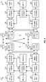
- FIG. 2 shows a block diagram of a design of a base station 105 and a UE 115 , which may be any of the base stations and one of the UEs in FIG. 1 .
- FIG. 2 illustrates components used to communicate signals between base station 105 and UE 115 . Such signals may include an update of a frequency setting of a frequency generator at UE 115 , which is communicated from UE 115 to base station 105 , as further described with reference to FIG. 3 .
- base station 105 may be small cell base station 105 f in FIG.
- UE 115 may be UE 115 c or 115 d operating in a service area of base station 105 f , which in order to access small cell base station 105 f , would be included in a list of accessible UEs for small cell base station 105 f .
- Base station 105 may also be a base station of some other type. As shown in FIG. 2 , base station 105 may be equipped with antennas 234 a through 234 t , and UE 115 may be equipped with antennas 252 a through 252 r for facilitating wireless communications.
- a transmit processor 220 may receive data from a data source 212 and control information from a controller/processor 240 .
- the control information may be for the physical broadcast channel (PBCH), physical control format indicator channel (PCFICH), physical hybrid-ARQ (automatic repeat request) indicator channel (PHICH), physical downlink control channel (PDCCH), enhanced physical downlink control channel (EPDCCH), MTC physical downlink control channel (MPDCCH), etc.
- the data may be for the PDSCH, etc.
- the transmit processor 220 may process (e.g., encode and symbol map) the data and control information to obtain data symbols and control symbols, respectively.
- the transmit processor 220 may also generate reference symbols, e.g., for the primary synchronization signal (PSS) and secondary synchronization signal (SSS), and cell-specific reference signal.
- Transmit (TX) multiple-input multiple-output (MIMO) processor 230 may perform spatial processing (e.g., precoding) on the data symbols, the control symbols, and/or the reference symbols, if applicable, and may provide output symbol streams to modulators (MODs) 232 a through 232 t .
- Each modulator 232 may process a respective output symbol stream (e.g., for OFDM, etc.) to obtain an output sample stream.
- Each modulator 232 may additionally or alternatively process (e.g., convert to analog, amplify, filter, and upconvert) the output sample stream to obtain a downlink signal.
- Downlink signals from modulators 232 a through 232 t may be transmitted via the antennas 234 a through 234 t , respectively.
- the antennas 252 a through 252 r may receive the downlink signals from the base station 105 and may provide received signals to the demodulators (DEMODs) 254 a through 254 r , respectively.
- Each demodulator 254 may condition (e.g., filter, amplify, downconvert, and digitize) a respective received signal to obtain input samples.
- Each demodulator 254 may further process the input samples (e.g., for OFDM, etc.) to obtain received symbols.
- MIMO detector 256 may obtain received symbols from demodulators 254 a through 254 r , perform MIMO detection on the received symbols if applicable, and provide detected symbols.
- Receive processor 258 may process (e.g., demodulate, deinterleave, and decode) the detected symbols, provide decoded data for the UE 115 to a data sink 260 , and provide decoded control information to a controller/processor 280 .
- a transmit processor 264 may receive and process data (e.g., for the physical uplink shared channel (PUSCH)) from a data source 262 and control information (e.g., for the physical uplink control channel (PUCCH)) from the controller/processor 280 . Transmit processor 264 may also generate reference symbols for a reference signal. The symbols from the transmit processor 264 may be precoded by TX MIMO processor 266 if applicable, further processed by the modulators 254 a through 254 r (e.g., for SC-FDM, etc.), and transmitted to the base station 105 .
- data e.g., for the physical uplink shared channel (PUSCH)
- control information e.g., for the physical uplink control channel (PUCCH)
- PUCCH physical uplink control channel
- the uplink signals from UE 115 may be received by antennas 234 , processed by demodulators 232 , detected by MIMO detector 236 if applicable, and further processed by receive processor 238 to obtain decoded data and control information sent by UE 115 .
- Receive processor 238 may provide the decoded data to data sink 239 and the decoded control information to controller/processor 240 .
- Controllers/processors 240 and 280 may direct the operation at base station 105 and UE 115 , respectively. Controller/processor 240 and/or other processors and modules at base station 105 and/or controller/processor 280 and/or other processors and modules at UE 115 may perform or direct the execution of various processes for the techniques described herein, such as to perform or direct the execution illustrated in FIGS. 7 and 8 , and/or other processes for the techniques described herein.
- Memories 242 and 282 may store data and program codes for base station 105 and UE 115 , respectively.
- Scheduler 244 may schedule UEs for data transmission on the downlink and/or uplink.
- Wireless communications systems operated by different network operating entities may share spectrum.
- a network operating entity may be configured to use an entirety of a designated shared spectrum for at least a period of time before another network operating entity uses the entirety of the designated shared spectrum for a different period of time.
- certain resources e.g., time
- a network operating entity may be allocated certain time resources reserved for exclusive communication by the network operating entity using the entirety of the shared spectrum.
- the network operating entity may also be allocated other time resources where the entity is given priority over other network operating entities to communicate using the shared spectrum.
- These time resources, prioritized for use by the network operating entity may be utilized by other network operating entities on an opportunistic basis if the prioritized network operating entity does not utilize the resources. Additional time resources may be allocated for any network operator to use on an opportunistic basis.
- Access to the shared spectrum and the arbitration of time resources among different network operating entities may be centrally controlled by a separate entity, autonomously determined by a predefined arbitration scheme, or dynamically determined based on interactions between wireless nodes of the network operators.
- UE 115 and base station 105 may operate in a shared radio frequency spectrum band, which may include licensed or unlicensed (e.g., contention-based) frequency spectrum.
- UEs 115 or base stations 105 may traditionally perform a medium-sensing procedure to contend for access to the frequency spectrum.
- UE 115 or base station 105 may perform a listen before talk (LBT) procedure such as a clear channel assessment (CCA) prior to communicating in order to determine whether the shared channel is available.
- LBT listen before talk
- CCA clear channel assessment
- a CCA may include an energy detection procedure to determine whether there are any other active transmissions.
- a device may infer that a change in a received signal strength indicator (RSSI) of a power meter indicates that a channel is occupied.
- RSSI received signal strength indicator
- a CCA also may include detection of specific sequences that indicate use of the channel.
- another device may transmit a specific preamble prior to transmitting a data sequence.
- an LBT procedure may include a wireless node adjusting its own backoff window based on the amount of energy detected on a channel and/or the acknowledge/negative-acknowledge (ACK/NACK) feedback for its own transmitted packets as a proxy for collisions.
- ACK/NACK acknowledge/negative-acknowledge
- base stations 105 and UEs 115 may be operated by the same or different network operating entities.
- an individual base station 105 or UE 115 may be operated by more than one network operating entity.
- each base station 105 and UE 115 may be operated by a single network operating entity. Requiring each base station 105 and UE 115 of different network operating entities to contend for shared resources may result in increased signaling overhead and communication latency.
- FIG. 3 illustrates an example of a wireless communications system 300 that supports sharing of frequency generator settings in accordance with aspects of the present disclosure.
- wireless communications system 300 may implement aspects of wireless communication system 100 .
- wireless communications system 300 may include UE 115 and base station 105 . Although one UE and one base station are illustrated, in other implementations, wireless communications system 300 may include multiple UEs 115 , multiple base stations 105 , or both.
- UE 115 includes processor 302 , memory 304 , transmitter 310 , receiver 312 , and frequency generator 314 .
- Processor 302 may be configured to execute instructions stored at memory 304 to perform the operations described herein.
- processor 302 includes or corresponds to controller/processor 280
- memory 304 includes or corresponds to memory 282 .
- Memory 304 may also be configured to store frequency settings associated with frequency generator 314 , as further described herein.
- Transmitter 310 is configured to transmit data to one or more other devices
- receiver 312 is configured to receive data from one or more other devices.
- transmitter 310 may transmit data
- receiver 312 may receive data, via a network, such as a wired network, a wireless network, or a combination thereof.
- UE 115 may be configured to transmit and/or receive data via a direct device-to-device connection, a local area network (LAN), a wide area network (WAN), a modem-to-modem connection, the Internet, intranet, extranet, cable transmission system, cellular communication network, any combination of the above, or any other communications network now known or later developed within which permits two or more electronic devices to communicate.
- LAN local area network
- WAN wide area network
- modem-to-modem connection the Internet, intranet, extranet, cable transmission system, cellular communication network, any combination of the above, or any other communications network now known or later developed within which permits two or more electronic devices to communicate.
- transmitter 310 and receiver 312 may be replaced with a transceiver. Additionally, or alternatively, transmitter 310 , receiver, 312 , or both may include or correspond to one or more components of UE 115 described with reference to FIG. 2 .
- Frequency generator 314 is configured to generate a signal having a particular frequency, based on a frequency setting.
- frequency generator 314 includes a local oscillator (LO).
- LO local oscillator
- frequency generator 314 includes a different type of signal generator.
- the frequency of the signal output by frequency generator 314 may be modified by changing the frequency setting associated with frequency generator 314 .
- frequency generator 314 may be configured to be set to one of multiple frequency settings at a given time, and the frequency setting determines the frequency of the output signal.
- Base station 105 includes processor 330 , memory 332 , transmitter 334 , and receiver 336 .
- Processor 330 may be configured to execute instructions stores at memory 332 to perform the operations described herein.
- processor 330 includes or corresponds to controller/processor 240
- memory 332 includes or corresponds to memory 242 .
- Memory 332 may also be configured to store frequency settings associated with frequency generator 314 , as further described herein.
- Transmitter 334 is configured to transmit data to one or more other devices
- receiver 336 is configured to receive data from one or more other devices.
- transmitter 334 may transmit data
- receiver 336 may receive data, via a network, such as a wired network, a wireless network, or a combination thereof.
- base station 105 may be configured to transmit and/or receive data via a direct device-to-device connection, a local area network (LAN), a wide area network (WAN), a modem-to-modem connection, the Internet, intranet, extranet, cable transmission system, cellular communication network, any combination of the above, or any other communications network now known or later developed within which permits two or more electronic devices to communicate.
- LAN local area network
- WAN wide area network
- modem-to-modem connection the Internet, intranet, extranet, cable transmission system, cellular communication network, any combination of the above, or any other communications network now known or later developed within which permits two or more electronic devices to communicate.
- transmitter 334 and receiver 336 may be replaced with a transceiver. Additionally, or alternatively, transmitter 334 , receiver, 336 , or both may include or correspond to one or more components of base station 105 described with reference to FIG. 2 .
- a first setting 306 is set (e.g., by processor 302 ) for frequency generator 314 .
- the first setting 306 may be set during an initial setup process of UE 115 (e.g., a radio resource control (RRC) configuration of UE 115 ).
- First setting 306 represents a frequency in approximately the center of a carrier bandwidth that UE 115 is configured to communicate via.
- frequency generator 314 Based on the first setting 306 , frequency generator 314 outputs a signal having a first frequency, which may be used for upconverting or downconverting signals received or transmitted by UE 115 (e.g., by transmitter 310 and/or receiver 312 ).
- first setting 306 is provided to base station 105 , and base station 105 stores first setting 306 at memory 332 .
- Base station 105 may perform one or more operations, such as direct current (DC) cancellation or scheduling for a DC subcarrier, based on first setting 306 . Performing such operations may include sending one or more messages including one or more instructions to UE 115 .
- DC direct current
- first setting 306 modifies first setting 306 to generate second setting 308 .
- First setting 306 is associated with a first frequency
- second setting 308 is associated with a second frequency that is different from the first frequency.
- first setting 306 may be associated with a frequency in approximately the center of a carrier bandwidth
- second setting 308 may be associated with a second frequency that is not in the center of a carrier bandwidth.
- first setting 306 may correspond to an initial frequency output by frequency generator 314
- second setting 308 may correspond to an adjusted frequency output by frequency generator 314 .
- frequency generator 314 Based on the second setting 308 , frequency generator 314 outputs a signal having the second frequency.
- UE 115 may modify first setting 306 to support one or more advanced features.
- UE 115 e.g., processor 302
- the fast frequency hopping mode may be associated with second setting 308 that is nearer to a frequency of a resource block (RB) assignment, as further described with reference to FIG. 4 .
- the fast frequency hopping mode is initiated based on a LTE band combination in an Evolved Universal Terrestrial Radio Access—New Radio Dual Connectivity (ENDC) mode.
- Evolved Universal Terrestrial Radio Access—New Radio Dual Connectivity (ENDC) mode Evolved Universal Terrestrial Radio Access—New Radio Dual Connectivity
- UE 115 may modify first setting 306 based on activation or deactivation of one or more carriers during operation in a shared transmit mode.
- WB wideband
- PLL phase-locked loop
- the frequency of frequency generator 314 may be set (e.g., by processor 302 ) to a frequency that is between two carriers, and common TX circuitry may be used for transmission in either carrier.
- UE 115 e.g., processor 302
- the band jammer mode may tune frequency generator 314 to an offset with respect to the center of the carrier bandwidth to counter or reduce the in band jammer and interference from transmitter 310 .
- the band jammer mode is associated with a single carrier, with carrier aggregation, or with ENDC combinations.
- UE 115 e.g., processor 302
- UE 115 may be a multi-radio or multiple subscription device, and UE 115 may modify first setting 306 based on interference caused by one radio to another radio (or to communications of one subscription to communications of another subscription), another co-existence constraint, or a combination thereof.
- UE 115 After generating second setting 308 , UE 115 (e.g., processor 302 ) generates a message 320 .
- Message 320 indicates second setting 308 .
- message 320 includes or corresponds to a UE assistance information message, and one or more information elements of the UE assistance information message indicate second setting 308 .
- message 320 (e.g., the UE assistance information message) includes an extendedRFSignalling information element, and the extendedRFSignalling information element indicates the second frequency setting.
- the following code provides an example of one implementation of a UE assistance information message:
- message 320 includes or corresponds to a media access control (MAC) control element.
- the MAC control element may indicate second setting 308 .
- the MAC control element corresponds to a single carrier. In other implementations, the MAC control element corresponds to multiple carriers. The MAC control element is further described herein with reference to FIGS. 5A and 5B .
- second setting 308 is indicated as a frequency.
- message 320 may indicate the frequency that second setting 308 corresponds to.
- second setting 308 is indicated as an offset from first setting 306 .
- message 320 may include an offset indicating the difference between first setting 306 and second setting 308 .
- the offset is indicated by a number of subcarriers.
- the offset may be indicated by a number of subcarriers in the range ( ⁇ 3299, 3299).
- the number of subcarriers may be in a different range (e.g., based on the number of digits in the field indicating the offset).
- the offset may be indicated in Hertz (Hz) from the center of the carrier.
- UE 115 (e.g., processor 302 ) is configured to maintain a timer to control the number of frequency settings messages that are transmitted by UE 115 (e.g., via transmitter 310 ). For example, UE 115 (e.g., processor 302 ) may initialize a timer upon transmission of message 320 , and UE 115 (e.g., processor 302 ) refrains from transmitting a second message until expiration of the timer. For example, if second setting 308 is modified to generate a third setting 324 at a time prior to expiration of the timer, UE 115 refrains from generating and transmitting an additional message 322 (indicating third setting 324 ) until expiration of the timer.
- second setting 308 is modified to generate a third setting 324 at a time prior to expiration of the timer
- UE 115 refrains from generating and transmitting an additional message 322 (indicating third setting 324 ) until expiration of the timer.
- the timer may have a fixed duration or may have a duration that corresponds to conditions at the network (e.g., the timer may be shorter, and thus more messages transmitted, if network conditions are favorable while the timer may be longer, and fewer messages are transmitted, if the network conditions are congested or poor).
- Base station 105 receives message 320 from UE 115 via receiver 336 .
- Message 320 is provided to processor 330 and processor 330 stores second setting 308 at memory 332 .
- Base station 105 (e.g., processor 330 ) may use second setting 308 to perform one or more operations.
- Performing the one or more operations may include transmitting a second message 340 from base station 105 (e.g., via transmitter 334 ) to UE 115 based on performance of the one or more operations.
- the one or more operations includes a DC cancellation operation.
- the one or more operations includes a scheduling operation for a DC subcarrier.
- base station 105 may refrain from measuring transmit performance metrics until expiration of a particular time period. Refraining from measuring transmit performance metrics until expiration of the particular time period may enable the operation to account for second setting 308 , thereby improving the transmit performance metrics when they are measured.
- the particular time period is fixed.
- the particular time period may be specified in an industry standard and may be preprogrammed at base station 105 (or based on user entry).
- message 320 includes an indication of a duration of the particular time period.
- UE 115 e.g., processor 302
- FIG. 3 describes sharing of frequency settings for frequency generator 314 between UE 115 and base station 105 .
- Providing updated frequency settings to base station 105 enables base station 105 to improve performance of one or more operations performed based on the updated frequency settings, such as DC cancellation or scheduling a DC subcarrier. Improving performance of such operations may improve various performance metrics associated with UE 115 , such as error vector magnitude (EVM), adjacent channel leakage ratio (ACLR), spectrum emission mask (SEM, and/or occupied bandwidth (OBW), which may also improve metrics such as signal-to-noise ratio (SNR) and effective maximum throughput.
- EVM error vector magnitude
- ACLR adjacent channel leakage ratio
- SEM spectrum emission mask
- OBW occupied bandwidth
- FIGS. 4A-4B illustrate examples of frequency settings for a frequency generator, such as frequency generator 314 (e.g., a LO).
- FIG. 4A illustrates a first graph 400 showing frequencies of various components of a transmission.
- the frequency generator e.g., the LO
- first frequency 402 is located at approximately the center of a carrier bandwidth that a UE communicates via.
- Additional intermodulation products such as HD2, HD4, P4FMOD, S4FMOD, and higher order modulation products are also illustrated. These intermodulation products may have frequencies that are based on a difference between first frequency 402 and a frequency of resource block 1RB that is assigned to the UE. In order to reduce the spread of the intermodulation products, the difference between first frequency 402 and the frequency of the resource block may be reduced.
- FIG. 4B illustrates a second graph 410 that corresponds to a fast frequency hopping operation.
- the frequency of the frequency generator has been changed to second frequency 412 , which is closer to the frequency range associated with the resource block 1RB.
- the various intermodulation products are more closely grouped and many overlap with the communication bandwidth, which reduces interference to other UEs communicating in other frequency bandwidths.
- the UE sends a message (e.g., message 320 ) that indicates second frequency 412 (e.g., a value of second frequency 412 or a value indicating an offset between second frequency 412 and first frequency 402 ) as described with reference to FIG. 3 .
- FIGS. 5A-5B illustrate examples of media access control (MAC) control elements (CEs) for conveying frequency settings of a frequency generator of a UE.
- the UE may include or correspond to UE 115
- the MAC control elements may include or correspond to message 320 of FIG. 3 .
- FIG. 5A illustrates a first MAC CE 500 .
- First MAC CE 500 corresponds to a single carrier.
- first MAC CE 500 includes one octet of information.
- the one octet of information may include information for secondary cell (Scell) activation or deactivation and a plurality of bits that indicate an updated frequency of a frequency generator (e.g., a LO).
- the updated frequency may be a frequency value or an offset value (from an initial frequency).
- FIG. 5B illustrates a second MAC CE 510 .
- Second MAC CE 510 corresponds to multiple carriers.
- second MAC CE 510 includes four octets of information.
- the four octets of information may include information for multiple Scell activation or deactivation and a plurality of bits that indicate an updated frequency of a frequency generator (e.g., a LO).
- the updated frequency may be a frequency value or an offset value (from an initial frequency).
- a UE may receive transmit either first MAC CE 500 or second MAC CE 510 as message 320 to indicate an updated frequency setting for the frequency generator.
- a base station e.g., base station 105
- FIG. 6 depicts a ladder diagram illustrating an example of sharing frequency settings for a frequency generator of a UE.
- a system of the ladder diagram includes UE 115 and base station 105 .
- UE 115 and base station 105 may include one or more components and be configured to perform one or more operations, as described with reference to FIGS. 1-3 .
- UE establishes (e.g., sets) a first frequency setting of a frequency generator of UE 115 .
- the first frequency setting may include or correspond to first setting 306
- the frequency generator may include or correspond to frequency generator 314 .
- the frequency generator is a local oscillator (LO).
- the first frequency setting may be shared with base station 105 , such as during a radio resource control (RRC) setup process, such that base station 105 stores the first frequency settings.
- RRC radio resource control
- the second frequency setting may include or correspond to second setting 308 .
- UE 115 may modify a frequency of a signal output by the LO.
- the second frequency setting corresponds to a second frequency that is different from a first frequency corresponding to the first frequency setting.
- the first frequency setting may correspond to a frequency that is substantially centered within an operating bandwidth
- the second frequency setting may correspond to a frequency that is closer to a frequency of an assigned resource block within the operating bandwidth.
- UE 115 sends a message to base station 105 to indicate the second frequency setting.
- the message may include or correspond to message 320 .
- the second frequency setting may be indicated by a frequency value or by an offset from the first frequency setting.
- the message is a UE assistance information message that indicates the second frequency setting.
- an extendedRFSignalling information element of the UE assistance information message may indicate the second frequency setting.
- the message is a MAC control element.
- the MAC control element may correspond to a single carrier or to multiple carriers.
- base station 105 performs one or more operations based on the second frequency settings.
- base station 105 may perform a DC cancellation operation or a scheduling operation for a DC subcarrier, as non-limiting examples.
- base station 105 sends a second message to UE 115 based on the operation.
- the second message may include or correspond to second message 340 .
- the second message may include an instruction to be performed at UE 115 to improve a signal quality metric, such as SNR or maximum throughput.
- FIG. 6 illustrates operations between a UE and a base station that enable the base station to receive updated frequency settings for a frequency generator at the UE.
- the base station may use the updated frequency settings to perform one or more operations that improve signal quality metrics associated with the UE.
- FIG. 7 is a block diagram illustrating example blocks executed by a UE configured according to an aspect of the present disclosure. The example blocks will also be described with respect to UE 115 as illustrated in FIG. 9 .
- FIG. 9 is a block diagram illustrating UE 115 configured according to one aspect of the present disclosure.
- UE 115 includes the structure, hardware, and components as illustrated for UE 115 of FIG. 2 .
- UE 115 includes controller/processor 280 , which operates to execute logic or computer instructions stored in memory 282 , as well as controlling the components of UE 115 that provide the features and functionality of UE 115 .
- UE 115 under control of controller/processor 280 , transmits and receives signals via wireless radios 900 a - r and antennas 252 a - r .
- Wireless radios 900 a - r includes various components and hardware, as illustrated in FIG. 2 for UE 115 , including modulator/demodulators 254 a - r , MIMO detector 256 , receive processor 258 , transmit processor 264 , and TX MIMO processor 266 .
- UE 115 may receive signals from and/or transmit signal to a base station, such as base station 105 as illustrated in FIG. 10 .
- the base station 105 of FIG. 10 includes similar components to UE 115 of FIG. 9 .
- the base station 105 may include corresponding components 1001 - 1004 which correspond to components 901 - 904 of the UE 115 .
- a UE determines a first frequency setting for a frequency generator of the UE.
- the first frequency setting is associated with a first frequency.
- a UE such as UE 115 , may execute, under control of controller/processor 280 , frequency generator control logic 901 , stored in memory 282 .
- the execution environment of frequency generator control logic 901 provides the functionality for UE 115 to set first setting 903 for the frequency generator (e.g., a LO).
- First setting 903 may include or correspond to first setting 306 .
- the execution environment of frequency generator control logic 901 determines different settings (associated with different frequencies) for the frequency generator of UE 115 .
- the UE modifies the first frequency setting to generate a second frequency setting for the frequency generator.
- the second frequency setting is associated with a second frequency that is different from the first frequency.
- the execution environment of frequency generator control logic 901 provides UE 115 the functionalities described with respect to the various aspects of the present disclosure.
- UE 115 under control of controller/processor 280 , modifies first setting 903 to generate second setting 904 for the frequency generator.
- Second setting 904 may include or correspond to second setting 308 .
- First setting 903 is associated with a first frequency (e.g., a frequency of a first signal output by the frequency generator) and second setting 904 is associated with a second frequency (e.g., a frequency of a second signal output by the frequency generator) that is different from the first frequency.
- settings of the frequency generator may be modified such that the frequency of the signal output by the frequency generator is different than an initial frequency, which may be a frequency of a center of a carrier with which UE 115 is configured to communicate via.
- second setting 904 may be generated based on initiation of a fast frequency hopping mode at UE 115 , based on activation or deactivation of one or more carriers during operation in a shared transmit mode at UE 115 , based on offset zero intermediate frequency/low intermediate frequency (OZIF/LIF) operations, or based on initiation of a band jammer mode at UE 115 , as non-limiting examples, or based on interference or a co-existence parameter associated with multiple radios or multiple subscriptions at UE 115 .
- OZIF/LIF offset zero intermediate frequency/low intermediate frequency
- the UE generates a message that indicates the second frequency setting.
- the UE e.g., UE 115
- the UE may execute, under control of controller/processor 280 , message TX/RX logic 902 , stored in memory 282 .
- the execution environment of message TX/RX logic 902 provides the functionality for UE 115 to generate the message.
- the message indicates second setting 904 .
- Second setting 904 may be indicated as a frequency value or as an offset value (e.g., from first setting 903 ), such as a number of subcarriers or a value in Hertz (Hz).
- the message is a UE assistance information message.
- the UE assistance information message includes an extendedRFSignalling information element, and the extendedRFSignalling information element indicates second setting 904 .
- the message is a MAC control element that can correspond to a single carrier or to multiple carriers.
- the UE transmits the message from the UE to a base station.
- UE 115 may transmit the message to base station 105 via wireless radios 900 a - r and antennas 252 a - r.
- FIG. 8 is a block diagram illustrating example blocks executed by a base station configured according to an aspect of the present disclosure. The example blocks will also be described with respect to base station 105 as illustrated in FIG. 10 .
- FIG. 10 is a block diagram illustrating base station 105 configured according to one aspect of the present disclosure.
- Base station 105 includes the structure, hardware, and components as illustrated for base station 105 of FIG. 2 .
- base station 105 includes controller/processor 240 , which operates to execute logic or computer instructions stored in memory 242 , as well as controlling the components of base station 105 that provide the features and functionality of base station 105 .
- Base station 105 under control of controller/processor 240 , transmits and receives signals via wireless radios 1000 a - t and antennas 234 a - t .
- Wireless radios 1000 a - t includes various components and hardware, as illustrated in FIG. 2 for base station 105 , including modulator/demodulators 232 a - t , transmit processor 220 , TX MIMO processor 230 , MIMO detector 236 , and receive processor 238 .
- a base station stores a first frequency setting for a frequency generator of a UE.
- the first frequency setting is associated with a first frequency.
- a base station such as base station 105 , may execute, under control of controller/processor 240 , message TX/RX logic 1001 , stored in memory 242 .
- the execution environment of message TX/RX logic 1001 provides the functionality for base station 105 to receive and store first setting 1003 corresponding to a frequency generator of a UE (e.g., UE 115 ).
- First setting 1003 may include or correspond to first setting 306 or first setting 903 .
- the execution environment of message TX/RX logic 1001 receives first setting 1003 (e.g., during a RRC configuration) and stores first setting 1003 at memory 242 .
- the base station receives a message from the UE.
- the message indicates a second frequency setting for the frequency generator.
- the second frequency setting is associated with a second frequency that is different from the first frequency.
- the execution environment of message TX/RX logic 1001 provides base station 105 the functionalities described with respect to the various aspects of the present disclosure.
- base station 105 under control of controller/processor 240 , receives the message via wireless radios 1000 a - t and antennas 234 a - t .
- Second setting 1004 may include or correspond to second setting 308 or second setting 904 .
- First setting 1003 is associated with a first frequency (e.g., a frequency of a first signal output by the frequency generator) and second setting 1004 is associated with a second frequency (e.g., a frequency of a second signal output by the frequency generator) that is different from the first frequency.
- settings of the frequency generator may be modified such that the frequency of the signal output by the frequency generator is different than an initial frequency, which may be a frequency of a center of a carrier with which UE 115 is configured to communicate via.
- the base station performs an operation based on the second frequency setting.
- the base station e.g., base station 105
- the base station may execute, under control of controller/processor 240 , operation performance logic 1002 , stored in memory 242 .
- the execution environment of operation performance logic 1002 provides the functionality for base station 105 to perform an operation based on second setting 1004 .
- the operation may include a DC cancellation operation or a scheduling operation for a DC subcarrier.
- the base station transmits a second message to the UE based on performance of the operation.
- base station 105 may execute message TX/RX logic 1001 to transmit a second message to UE 115 via wireless radios 1000 a - t and antennas 234 a - t .
- the message may include an instruction to be performed at UE 115 to improve a signal quality metric associated with UE 115 .
- enabling sharing of frequency generator settings may include additional aspects, such as any single aspect or any combination of aspects described below and/or in connection with one or more other processes or devices described elsewhere herein.
- enabling sharing of frequency generator settings may include an apparatus determining a first frequency setting for a frequency generator. The first frequency setting is associated with a first frequency. The apparatus may also modify the first frequency setting to generate a second frequency setting for the frequency generator. The second frequency setting is associated with a second frequency that is different from the first frequency. The apparatus may also generate a message that indicates the second frequency setting. The apparatus may further transmit the message to a base station.
- the apparatus includes a wireless device, such as a UE.
- the apparatus may include at least one processor, and a memory coupled to the processor.
- the processor may be configured to perform operations described herein with respect to the wireless device.
- the apparatus may include a non-transitory computer-readable medium having program code recorded thereon and the program code may be executable by a computer for causing the computer to perform operations described herein with reference to the wireless device.
- the apparatus may include one or more means configured to perform operations described herein.
- the frequency generator comprises a local oscillator.
- the message comprises a UE assistance information message.
- the UE assistance information message includes an extendedRFSignalling information element.
- the extendedRFSignalling information element indicates the second frequency setting.
- the message comprises a MAC control element.
- the MAC control element corresponds to a single carrier.
- the MAC control element corresponds to multiple carriers.
- the first frequency setting corresponds to an initial frequency output by the frequency generator.
- the second frequency setting corresponds to an adjusted frequency output by the frequency generator.
- the second frequency setting is indicated by the second frequency.
- the second frequency setting is indicated as an offset from the first frequency setting.
- the offset is indicated by a number of subcarriers.
- the offset is indicated in Hertz.
- the apparatus initializes a timer upon transmission of the message and refrains from transmitting a second message until expiration of the timer.
- the second message indicates a third frequency setting for the frequency generator.
- no transmit performance measurements are to be performed at the base station prior to the start time.
- the first frequency setting is modified based on initiation of a fast frequency hopping mode at the apparatus.
- the fast frequency hopping mode is initiated based on a long-term evolution band combination in an Evolved Universal Terrestrial Radio Access—New Radio Dual Connectivity mode.
- the first frequency setting is modified based on activation or deactivation of one or more carriers during operation in a shared transmit mode.
- the first frequency setting is modified based on initiation of a band jammer mode of the apparatus, based on interference or a co-existence parameter associated with multiple radios or multiple subscriptions at the apparatus, or a combination thereof.
- the band jammer mode is associated with a single carrier, with carrier aggregation, or with Evolved Universal Terrestrial Radio Access—New Radio Dual Connectivity.
- an apparatus configured for wireless communication such as a base station, is configured to store a first frequency setting for a frequency generator of a UE.
- the first frequency setting is associated with a first frequency.
- the apparatus is also configured to receive a message from the UE.
- the message indicates a second frequency setting for the frequency generator.
- the second frequency setting is associated with a second frequency that is different from the first frequency.
- the apparatus is also configured to perform an operation based on the second frequency setting.
- the apparatus is further configured to transmit a second message to the UE based on performance of the operation.
- the apparatus includes a wireless device, such as a base station.
- the apparatus may include at least one processor, and a memory coupled to the processor.
- the processor may be configured to perform operations described herein with respect to the wireless device.
- the apparatus may include a non-transitory computer-readable medium having program code recorded thereon and the program code may be executable by a computer for causing the computer to perform operations described herein with reference to the wireless device.
- the apparatus may include one or more means configured to perform operations described herein.
- the operation comprises a DC cancellation operation.
- the operation comprises a scheduling operation for a DC subcarrier.
- the first frequency setting is stored during an initial setup process of the UE.
- the frequency generator comprises a local oscillator of the UE.
- the message comprises a UE assistance information message.
- the UE assistance information message includes an extendedRFSignalling information element.
- the extendedRFSignalling information element indicates the second frequency setting.
- the message comprises a MAC control element.
- the MAC control element corresponds to a single carrier.
- the MAC control element corresponds to multiple carriers.
- the second frequency setting is indicated as the second frequency.
- the second frequency setting is indicated as an offset from the first frequency setting.
- the offset is indicated by a number of subcarriers.
- the apparatus refrains from measuring transmit performance metrics until expiration of a particular time period.
- the particular time period is fixed.
- the message further includes an indication of a duration of the particular time period.
- the functional blocks and modules described herein may comprise processors, electronics devices, hardware devices, electronics components, logical circuits, memories, software codes, firmware codes, etc., or any combination thereof.
- DSP digital signal processor
- ASIC application specific integrated circuit
- FPGA field programmable gate array
- a general-purpose processor may be a microprocessor, but in the alternative, the processor may be any conventional processor, controller, microcontroller, or state machine.
- a processor may also be implemented as a combination of computing devices, e.g., a combination of a DSP and a microprocessor, a plurality of microprocessors, one or more microprocessors in conjunction with a DSP core, or any other such configuration.
- a software module may reside in RAM memory, flash memory, ROM memory, EPROM memory, EEPROM memory, registers, hard disk, a removable disk, a CD-ROM, or any other form of storage medium known in the art.
- An exemplary storage medium is coupled to the processor such that the processor can read information from, and write information to, the storage medium.
- the storage medium may be integral to the processor.
- the processor and the storage medium may reside in an ASIC.
- the ASIC may reside in a user terminal.
- the processor and the storage medium may reside as discrete components in a user terminal.
- the functions described may be implemented in hardware, software, firmware, or any combination thereof. If implemented in software, the functions may be stored on or transmitted over as one or more instructions or code on a computer-readable medium.
- Computer-readable media includes both computer storage media and communication media including any medium that facilitates transfer of a computer program from one place to another. Computer-readable storage media may be any available media that can be accessed by a general purpose or special purpose computer.
- such computer-readable media can comprise RAM, ROM, EEPROM, CD-ROM or other optical disk storage, magnetic disk storage or other magnetic storage devices, or any other medium that can be used to carry or store desired program code means in the form of instructions or data structures and that can be accessed by a general-purpose or special-purpose computer, or a general-purpose or special-purpose processor.
- a connection may be properly termed a computer-readable medium.
- the software is transmitted from a website, server, or other remote source using a coaxial cable, fiber optic cable, twisted pair, or digital subscriber line (DSL), then the coaxial cable, fiber optic cable, twisted pair, or DSL, are included in the definition of medium.
- DSL digital subscriber line
- Disk and disc includes compact disc (CD), laser disc, optical disc, digital versatile disc (DVD), floppy disk and blu-ray disc where disks usually reproduce data magnetically, while discs reproduce data optically with lasers. Combinations of the above should also be included within the scope of computer-readable media.
- the term “and/or,” when used in a list of two or more items, means that any one of the listed items can be employed by itself, or any combination of two or more of the listed items can be employed.
- the composition can contain A alone; B alone; C alone; A and B in combination; A and C in combination; B and C in combination; or A, B, and C in combination.
Landscapes
- Engineering & Computer Science (AREA)
- Computer Networks & Wireless Communication (AREA)
- Signal Processing (AREA)
- Mobile Radio Communication Systems (AREA)
Abstract
Description
| -- ASN1START |
| -- TAG-UEASSISTANCEINFORMATION-START |
| UEAssistanceInformation ::= SEQUENCE { |
| criticalExtensions CHOICE { |
| ueAssistanceInformation UEAssistanceInformation-IEs, |
| criticalExtensionsFuture SEQUENCE{ } |
| } |
| } |
| UEAssistanceInformation-IEs ::= SEQUENCE { |
| delayBudgetReport DelayBudgetReport OPTIONAL, |
| extendedRFSignalling extendedRFSignalling OPTIONAL, |
| lateNonCriticalExtension OCTET STRING OPTIONAL, |
| nonCriticalExtension UEAssistanceInformation-v1540-IEs OPTIONAL |
| } |
| UEAssistanceInformation-v1540-IEs ::= SEQUENCE { |
| extendedRFSignalling extended RFSignalling OPTIONAL, |
| nonCriticalExtension SEQUENCE { } OPTIONAL |
| } |
| extendedRF Signalling ::= SEQUENCE { |
| LoChange SEQUENCE { |
| LoOffset INTEGER (0..3299, 0 to −3299), |
| } OPTIONAL, |
| reducedMaxBW-FR1 SEQUENCE { |
| reducedBW-FR1-DL ReducedAggregatedBandwidth, |
| reducedBW-FR1-UL ReducedAggregatedBandwidth |
| } OPTIONAL, |
| } |
Claims (30)
Priority Applications (4)
| Application Number | Priority Date | Filing Date | Title |
|---|---|---|---|
| US16/922,627 US11368185B2 (en) | 2019-07-17 | 2020-07-07 | Sharing frequency generator settings in networks |
| PCT/US2020/041251 WO2021011265A1 (en) | 2019-07-17 | 2020-07-08 | Sharing frequency generator settings in networks |
| CN202080051296.3A CN114128155B (en) | 2019-07-17 | 2020-07-08 | Shared frequency generator settings in a network |
| EP20751406.8A EP4000182A1 (en) | 2019-07-17 | 2020-07-08 | Sharing frequency generator settings in networks |
Applications Claiming Priority (2)
| Application Number | Priority Date | Filing Date | Title |
|---|---|---|---|
| US201962875269P | 2019-07-17 | 2019-07-17 | |
| US16/922,627 US11368185B2 (en) | 2019-07-17 | 2020-07-07 | Sharing frequency generator settings in networks |
Publications (2)
| Publication Number | Publication Date |
|---|---|
| US20210021299A1 US20210021299A1 (en) | 2021-01-21 |
| US11368185B2 true US11368185B2 (en) | 2022-06-21 |
Family
ID=71948742
Family Applications (1)
| Application Number | Title | Priority Date | Filing Date |
|---|---|---|---|
| US16/922,627 Active 2040-09-25 US11368185B2 (en) | 2019-07-17 | 2020-07-07 | Sharing frequency generator settings in networks |
Country Status (4)
| Country | Link |
|---|---|
| US (1) | US11368185B2 (en) |
| EP (1) | EP4000182A1 (en) |
| CN (1) | CN114128155B (en) |
| WO (1) | WO2021011265A1 (en) |
Families Citing this family (1)
| Publication number | Priority date | Publication date | Assignee | Title |
|---|---|---|---|---|
| WO2021087846A1 (en) * | 2019-11-07 | 2021-05-14 | Zte Corporation | Methods, apparatus and systems for determining a resource for wake-up signal transmissions |
Citations (6)
| Publication number | Priority date | Publication date | Assignee | Title |
|---|---|---|---|---|
| US5852630A (en) * | 1997-07-17 | 1998-12-22 | Globespan Semiconductor, Inc. | Method and apparatus for a RADSL transceiver warm start activation procedure with precoding |
| EP2081395A1 (en) | 2006-11-10 | 2009-07-22 | Fujitsu Limited | Wireless communication system and wireless terminal device |
| US20090323608A1 (en) * | 2008-06-30 | 2009-12-31 | Kabushiki Kaisha Toshiba | Apparatus and method for wireless communication |
| US20100034108A1 (en) * | 2006-11-01 | 2010-02-11 | Fujitsu Limited | Wireless Communication System |
| US20110151791A1 (en) * | 2009-12-21 | 2011-06-23 | James Snider | Apparatus And Method For Maintaining Communication With A Stolen Vehicle Tracking Device |
| JP2012090273A (en) | 2011-10-31 | 2012-05-10 | Fujitsu Ltd | Radio communication system |
Family Cites Families (5)
| Publication number | Priority date | Publication date | Assignee | Title |
|---|---|---|---|---|
| CN102957461B (en) * | 2011-08-22 | 2015-06-17 | 鼎桥通信技术有限公司 | Downlink signal transmission method and wireless communication system |
| US20150181546A1 (en) * | 2012-07-23 | 2015-06-25 | Interdigital Patent Holdings, Inc. | Methods and apparatus for frequency synchronization, power control, and cell configuration for ul-only operation in dss bands |
| US9350523B2 (en) * | 2013-11-21 | 2016-05-24 | At&T Intellectual Property I, Lp | Dynamic access management of wireless communication resources |
| US20160345323A1 (en) * | 2015-05-18 | 2016-11-24 | Qualcomm Incorporated | Dynamic frequency selection procedures in wireless modems |
| US10637445B2 (en) * | 2017-10-18 | 2020-04-28 | Phazr, Inc. | Signaling methods for communication systems with widely spaced downlink and uplink frequency channels |
-
2020
- 2020-07-07 US US16/922,627 patent/US11368185B2/en active Active
- 2020-07-08 CN CN202080051296.3A patent/CN114128155B/en active Active
- 2020-07-08 EP EP20751406.8A patent/EP4000182A1/en active Pending
- 2020-07-08 WO PCT/US2020/041251 patent/WO2021011265A1/en not_active Ceased
Patent Citations (7)
| Publication number | Priority date | Publication date | Assignee | Title |
|---|---|---|---|---|
| US5852630A (en) * | 1997-07-17 | 1998-12-22 | Globespan Semiconductor, Inc. | Method and apparatus for a RADSL transceiver warm start activation procedure with precoding |
| US20100034108A1 (en) * | 2006-11-01 | 2010-02-11 | Fujitsu Limited | Wireless Communication System |
| EP2081395A1 (en) | 2006-11-10 | 2009-07-22 | Fujitsu Limited | Wireless communication system and wireless terminal device |
| US20090213806A1 (en) * | 2006-11-10 | 2009-08-27 | Fujitsu Limited | Wireless communication system and wireless terminal device |
| US20090323608A1 (en) * | 2008-06-30 | 2009-12-31 | Kabushiki Kaisha Toshiba | Apparatus and method for wireless communication |
| US20110151791A1 (en) * | 2009-12-21 | 2011-06-23 | James Snider | Apparatus And Method For Maintaining Communication With A Stolen Vehicle Tracking Device |
| JP2012090273A (en) | 2011-10-31 | 2012-05-10 | Fujitsu Ltd | Radio communication system |
Non-Patent Citations (2)
| Title |
|---|
| International Search Report and Written Opinion—PCT/US2020/041251—ISA/EPO—dated Oct. 28, 2020 (192983WO). |
| PCT/2007/058490 A by Go, Gwangzeen (Year: 2007). * |
Also Published As
| Publication number | Publication date |
|---|---|
| CN114128155B (en) | 2023-05-12 |
| WO2021011265A1 (en) | 2021-01-21 |
| EP4000182A1 (en) | 2022-05-25 |
| US20210021299A1 (en) | 2021-01-21 |
| CN114128155A (en) | 2022-03-01 |
Similar Documents
| Publication | Publication Date | Title |
|---|---|---|
| US11973598B2 (en) | Enhancements for sidelink carrier aggregation feedback | |
| US12289696B2 (en) | User equipment behavior on obtaining new radio early measurement configuration | |
| US11589252B2 (en) | Configuration for a channel measurement resource (CMR) or an interference measurement resource (IMR) time restriction | |
| US11924827B2 (en) | UE processing time for PDSCH repetition in the same slot | |
| US11864208B2 (en) | Control resource set (CORESET) allocation for reduced bandwidth devices in 5G-NR | |
| US20250240804A1 (en) | Demodulation reference signal grouping for full duplex wireless communications | |
| US11723044B2 (en) | Control resource set with larger allocation in the time domain for reduced bandwidth devices | |
| US20210058829A1 (en) | Full configuration handover techniques | |
| US12581487B2 (en) | Search space set for monitoring physical downlink control channel (PDCCH) of one cell in multiple cells | |
| US12341720B2 (en) | Cross carrier activation of a periodic grant | |
| US11832268B2 (en) | Frequency resource allocation of a bandwidth part for multiple communication types | |
| US12604330B2 (en) | Multi-beam techniques for small data transfer over preconfigured uplink resources | |
| US11115990B2 (en) | UE autonomous beam selection | |
| US11368185B2 (en) | Sharing frequency generator settings in networks | |
| US11799567B2 (en) | Beam-specific RSSI and CO for NR-U | |
| US12557085B2 (en) | Group common demodulation reference signal for multiple user equipments | |
| US20240340053A1 (en) | Reliability enhancements for implicit beam switch | |
| WO2021179303A1 (en) | Power headroom reporting for a full-duplex mode of operation of a device | |
| US12550163B2 (en) | NR sidelink transmission gap | |
| US12615120B2 (en) | Uplink control channel group and cross-carrier scheduling for user equipment cooperation | |
| US12621733B2 (en) | Inter-rat measurement gap configuration | |
| US20240015751A1 (en) | Enhanced implicit pucch resource indication and identification techniques | |
| US20230156543A1 (en) | Inter-rat measurement gap configuration |
Legal Events
| Date | Code | Title | Description |
|---|---|---|---|
| FEPP | Fee payment procedure |
Free format text: ENTITY STATUS SET TO UNDISCOUNTED (ORIGINAL EVENT CODE: BIG.); ENTITY STATUS OF PATENT OWNER: LARGE ENTITY |
|
| STPP | Information on status: patent application and granting procedure in general |
Free format text: DOCKETED NEW CASE - READY FOR EXAMINATION |
|
| AS | Assignment |
Owner name: QUALCOMM INCORPORATED, CALIFORNIA Free format text: ASSIGNMENT OF ASSIGNORS INTEREST;ASSIGNOR:KUMAR, AKASH;REEL/FRAME:054709/0215 Effective date: 20201209 |
|
| STPP | Information on status: patent application and granting procedure in general |
Free format text: NON FINAL ACTION MAILED |
|
| AS | Assignment |
Owner name: QUALCOMM INCORPORATED, CALIFORNIA Free format text: ASSIGNMENT OF ASSIGNORS INTEREST;ASSIGNOR:KUMAR, AKASH;REEL/FRAME:058370/0783 Effective date: 20201209 |
|
| STPP | Information on status: patent application and granting procedure in general |
Free format text: RESPONSE TO NON-FINAL OFFICE ACTION ENTERED AND FORWARDED TO EXAMINER |
|
| STPP | Information on status: patent application and granting procedure in general |
Free format text: NOTICE OF ALLOWANCE MAILED -- APPLICATION RECEIVED IN OFFICE OF PUBLICATIONS |
|
| STPP | Information on status: patent application and granting procedure in general |
Free format text: PUBLICATIONS -- ISSUE FEE PAYMENT VERIFIED |
|
| STCF | Information on status: patent grant |
Free format text: PATENTED CASE |
|
| MAFP | Maintenance fee payment |
Free format text: PAYMENT OF MAINTENANCE FEE, 4TH YEAR, LARGE ENTITY (ORIGINAL EVENT CODE: M1551); ENTITY STATUS OF PATENT OWNER: LARGE ENTITY Year of fee payment: 4 |