US1136070A - Pumping system. - Google Patents
Pumping system. Download PDFInfo
- Publication number
- US1136070A US1136070A US68068412A US1912680684A US1136070A US 1136070 A US1136070 A US 1136070A US 68068412 A US68068412 A US 68068412A US 1912680684 A US1912680684 A US 1912680684A US 1136070 A US1136070 A US 1136070A
- Authority
- US
- United States
- Prior art keywords
- chamber
- valve
- pipe
- pressure
- liquid
- Prior art date
- Legal status (The legal status is an assumption and is not a legal conclusion. Google has not performed a legal analysis and makes no representation as to the accuracy of the status listed.)
- Expired - Lifetime
Links
- 238000005086 pumping Methods 0.000 title description 28
- 239000007788 liquid Substances 0.000 description 74
- XLYOFNOQVPJJNP-UHFFFAOYSA-N water Substances O XLYOFNOQVPJJNP-UHFFFAOYSA-N 0.000 description 33
- 238000005266 casting Methods 0.000 description 21
- 239000012530 fluid Substances 0.000 description 17
- 238000009428 plumbing Methods 0.000 description 6
- 238000004891 communication Methods 0.000 description 5
- 230000006835 compression Effects 0.000 description 5
- 238000007906 compression Methods 0.000 description 5
- 230000008878 coupling Effects 0.000 description 5
- 238000010168 coupling process Methods 0.000 description 5
- 238000005859 coupling reaction Methods 0.000 description 5
- 230000007246 mechanism Effects 0.000 description 5
- 230000001105 regulatory effect Effects 0.000 description 4
- 244000261422 Lysimachia clethroides Species 0.000 description 3
- 230000009471 action Effects 0.000 description 3
- 210000004907 gland Anatomy 0.000 description 3
- MJBPUQUGJNAPAZ-AWEZNQCLSA-N butin Chemical compound C1([C@@H]2CC(=O)C3=CC=C(C=C3O2)O)=CC=C(O)C(O)=C1 MJBPUQUGJNAPAZ-AWEZNQCLSA-N 0.000 description 2
- 238000010276 construction Methods 0.000 description 2
- 150000004985 diamines Chemical class 0.000 description 2
- 210000003414 extremity Anatomy 0.000 description 2
- 230000004941 influx Effects 0.000 description 2
- 210000003141 lower extremity Anatomy 0.000 description 2
- 210000002445 nipple Anatomy 0.000 description 2
- ORILYTVJVMAKLC-UHFFFAOYSA-N Adamantane Natural products C1C(C2)CC3CC1CC2C3 ORILYTVJVMAKLC-UHFFFAOYSA-N 0.000 description 1
- 241001136792 Alle Species 0.000 description 1
- 241001153886 Ami Species 0.000 description 1
- 241000606643 Anaplasma centrale Species 0.000 description 1
- 241000272814 Anser sp. Species 0.000 description 1
- 241000370685 Arge Species 0.000 description 1
- MJBPUQUGJNAPAZ-UHFFFAOYSA-N Butine Natural products O1C2=CC(O)=CC=C2C(=O)CC1C1=CC=C(O)C(O)=C1 MJBPUQUGJNAPAZ-UHFFFAOYSA-N 0.000 description 1
- 125000002842 L-seryl group Chemical group O=C([*])[C@](N([H])[H])([H])C([H])([H])O[H] 0.000 description 1
- 241001585676 Orthonama obstipata Species 0.000 description 1
- 235000008331 Pinus X rigitaeda Nutrition 0.000 description 1
- 235000011613 Pinus brutia Nutrition 0.000 description 1
- 241000018646 Pinus brutia Species 0.000 description 1
- 241001116498 Taxus baccata Species 0.000 description 1
- 238000009825 accumulation Methods 0.000 description 1
- 238000013459 approach Methods 0.000 description 1
- 235000013405 beer Nutrition 0.000 description 1
- 238000006073 displacement reaction Methods 0.000 description 1
- 239000010985 leather Substances 0.000 description 1
- 239000000463 material Substances 0.000 description 1
- 238000000034 method Methods 0.000 description 1
- 238000012986 modification Methods 0.000 description 1
- 230000004048 modification Effects 0.000 description 1
- 230000000284 resting effect Effects 0.000 description 1
- 230000000717 retained effect Effects 0.000 description 1
- 230000000630 rising effect Effects 0.000 description 1
- 239000007787 solid Substances 0.000 description 1
- 230000000153 supplemental effect Effects 0.000 description 1
- 210000003462 vein Anatomy 0.000 description 1
- 238000013022 venting Methods 0.000 description 1
Images


Classifications
-
- F—MECHANICAL ENGINEERING; LIGHTING; HEATING; WEAPONS; BLASTING
- F04—POSITIVE - DISPLACEMENT MACHINES FOR LIQUIDS; PUMPS FOR LIQUIDS OR ELASTIC FLUIDS
- F04F—PUMPING OF FLUID BY DIRECT CONTACT OF ANOTHER FLUID OR BY USING INERTIA OF FLUID TO BE PUMPED; SIPHONS
- F04F1/00—Pumps using positively or negatively pressurised fluid medium acting directly on the liquid to be pumped
- F04F1/06—Pumps using positively or negatively pressurised fluid medium acting directly on the liquid to be pumped the fluid medium acting on the surface of the liquid to be pumped
Definitions
- a second coupling 24 Screwed upon the upper end 'of the pipe 10 and resting upon the cap 9 is a second coupling 24, and from said coupling cap the air chamber pipe extends downwardly, nearly to the lower end of the tube 10, and into the vicinity of the pumping waterlevel as indicated in Fig. le. From the upper end of the coupling cap 24, I extend ⁇ theshort nipple 26, leading tofthe standard T' 27 ,i and from the latter, I lead the discharge pipe 2S.
- pipe 22 form chambers separated from' each othery by the diaphragm l5, and that saidl chambers have no communication with each other, except through the valve 19 at' the lower-most end of the pipe 18.
- I secure the T 33, Aand 'from its lateral opening 34, I extend a pipe to the lower end of the reversing valve 3, as clearly shown in Fig. l1.
- the upper opening of the T 33 is provided with a gland 36 through which extends the pipe 37 down through the interior of the pipe 30 toits lowermost extremity through the pipe 32, where it is screwed into a by pass 38 in the by pass casting 14 from whichlby pass leads a pipe 39 down to a point somewhat below the upper discharge valve 19.
- I may, if desired, insert at the coupling l4l what I term a capacity disk, that is to say, a disk or diaphragm located in the discharge opening of the pipe 2S, having a central' aperture therethrough, which aperture has a diameter less than the internal diameter of the pipe 28, so that the capacity of the pumping system may be reduced below the'normalcapacity of the 'discharge pipe 28.
- the discharge pipe 28 leads to the closed house -plumbing system, and it is to be understood that such system is normally closed and opened only when water is to be drawn from some one of the reversing valve.
- This valve consists of the case 41 provided with the upper and lower coupling flanges 42 and 43, theA latter a'ording means for connection with theair pipe 35.
- Thev interior of the case is divided into several chambers, first, the upper piston valve y.chamber 44 leading to the annular chamber 45, which latter chamber communicates directly with the pipe 2 vleading from the' air receiver 1.
- This vannular chamber communicatesy with a cylindrical passage 46 .to a lower air chamber 47. in the center of which islocated van exhaust passage 48,' the latter leading out through the orifice 49'to rthe exterior of the' case.
- Th'passag'e 4S is y,of the same diameter as the passage 46 and their diameters are slightly less than theV diameter of the upper chamber 44. rThe an- 'nular Achamber 47 is in direct communication'yvith the air pipe35. Located in the chamber 44 and lowerv passage 48 is the spool piston valve 50.
- This piston valve consists of yan upper head 51 neatly fitting the upper chamber 44, anda lower valve head 52, the latter fitted to the passages 4G Aand 48. 4vThe lower end of the head 52 is slightly conical l as at 53, so as to fit the valve seat 54.
- this tension spring 62 is to hold the puppet yvalve, 58 upon its seat and thus throttle the-exhaust.A
- the throttle elbow 56 may be cnneetedby the pipe 63V with the well curb pipe 8, as illustrated in Fig. l", so rthat in case there should be any vexcessive noise it may be muliled or any water dripv will be discharged directly back into the well.
- the supplemental piston valve case 34 Coupled to the upper end of the 'casev41 through the'ilange 42 is the supplemental piston valve case 34.
- This latterV case' is'provided with the upper piston and-valvecham# ber 65 and the lower valve lchamber 66.
- the lower' chamber 66 is formed .counterboring the lower-end of '64, screwthre'ading Athe same for a considerable Vdistance and then inserting'the screw -threaded thimble 6T therein.
- This thinible 6T is provided with a .central aperture.
- vTile diaphragm valve 87 consists of the main casting' 91 provided with the @erwies 92 and 93, the former being connected with l the oe'p Qso as to forro a trap or Water seei, the purposevoi which will be hereiiiafter explained.
- the lower passage 93 is connected directly with the oenrel tube 3'? leading down into the inerior ei' the eir pipe 30 as heretofore aieseribed.
- rEhe reguiting faire "1' shown in vertieei cross section in Fig. 2 is as heretofore steced, ioeeie in the :gir pipe 2 leading from the air receiver so he reversing valve.
- This Valve Consists essentially of the lower cast ing 100, the inermeiiiaite casting 101 the upper casting 102.
- the lower casting s provided with ehe two chambers 103 en@ roe, ing therein the passage 10S.
- the upper side oie the diaphragm 105 is formed into e faire seat 107.
- the chamber 100 is located the holow valve plug 111 the ioWe-rjend of which yis provied with the esher peeking 112, o
- the chain-y ber 122 is formed by means of a flexible diaphragm 124 made of rubber, specially treated leather or other material impervious to Water.
- This diaphragm 124 is held in position by the flange 125 of the upper easting 102, by means of the bolts 126.
- Secured is a downwardly extending boss 127 which extends into the chamber 117.
- the [iat spring seat 128 With its upwardly projecting boss 129, for supporting the lower end of the compression spring 130.
- the cap 131 Upon the upper end of the spring 130 is located the cap 131 which has marginal slots taking over the internal guide 'ribs 132,v so as to vprevent the rotation of said cap 131.
- the compression of the spring 130 is effected by means of a screw 133, which is screwed into the central aperture of said cap, said screw being provided with a collar 134 which bears upon the under -side of the doinelike top of the casting 102.
- the upper end of the bolt 133 projects outside of the dome land is squared as at 135, so that the bolt may beA turned by means of a wrench when itis desired to adjust the compression of the.
- the plug valve 111 is made to move easily within the chamber 109 with a very slight clearance, so that ai-r pressure coming through the pipe 2 int-othe chamber 103 may gradually'lind its way from said' chamber 103 into the chamber. 109, so as to equalize bothlabove and'below the Valve 111, or if desired, the valve 111 may be made to fit the chamber 109 quite closelyV and the leakage from the chamber 103 into chamber 109 be provided for by a small by pass,kat 13G.
- zeguating miie T is so stop nii the ai? from the pmipng system after the same has been supji'iiec with en initia charge and then permit hnl charge to be exliiausied to e, Certain pein. men s, new charge of is aclfrfzited to the' system freni the receiver n this manner, the air receive?, into which gees the principal cos; of masenance, is iseated from the pumping sfsten: exsep at times when the nii -in said sysem nees repienismng, Y
- pumping system is sppiieabie to wells of erimm'y el medium deph; but in Order te adam is se weis of Hreuei' depth, nd it admsebieto eevse he 'fmu the WGH .by ssges sn for shut Tensen he duplex form, ns iustmted in Fig: T is use-d.' In this ease is necessary also to siightijf modify the reversing vaive 3, se that for tiieduplex system the veves 31 and 32 :me se intereonneced es to sperate atemate y. In Fig.
- the spring 7s' located Within this chamber 66 serves to hold the puppet valve 70" upon its seat.
- vbell crank lijl Adjacent to the opening 65 1 locate the vbell crank lijl with one arm thereot ⁇ project ing'y into the chamber 65 for contact With theuppcr ,end oi the valve stem 71.
- vA corresponding bell crank 165 is connected to the twin reversing valve in identically the same manner and for the same purpose.
- T he casting Gel is provided with an upper chamber 652 for the reception of the piston 76".
- lhis piston' is slightly different from the corresponding piston illustrated in Fig, 3, inasmuch as it is provided with a valve 762 Lpon its upper end 'for coperation with the valve seat 762, the purpose'oi' which will be hereinafter 'fully described.
- the piston 76" is fnrther provided with a. depending stein 764 which passes through an aperture in the casting and extends into the chamber G5 in position to engage the-inner arm of the toggle lever 164.
- l provide the chamber 652 with a lateral discharge or exhaustopeningffl to correspond with the passage 88 ol'l the valve shown in Fig. fl.
- each of the valves 31 and-32 may be provided with a side passage 88 leading from the exhaust passage 49 up to the upper castings 64 in the same manner as is shown in Fig. l; butin such case, I would dispense with the pipe 882 and l its connection with theexhaust T 56.
- a source of fluid pressure a liquid rhumber, inlet and disg'arge valves4 for said chamber, a rcversi'g valve for admitting pressure from said-'supply toand exhausting the'same from said liquid chamber, and a differential pressure ⁇ operated means actu ated by thev lowering of the liquid in said ,liquid chamber to admit said fluid pressure to and for actuating said reversing valve to ehlmff't the Pressure from said liquid Chim?
- valve operatedA .Y by a differential. of pressure between sald A discharge pipe and said liquid chamber.
- a pumping system the combination of a liquid chamber, a valved inlet and a valved and ,normally closed dischargepipe for said chamber, a valve for exhausting the vpressure from said chamber to cause an in- Vhausting 'pressurp from said chamber to cause'arrise of liquid'therein, and for admitting pressure thereto to cause a vdischarge of liquid therefrom into said discharge pipe, means comprising a diaphragm valve operated by a differential of pressure 'between said discharge pipe and said liquid chamber 'ico' 'to admit accumulated pressure from said liquid chamber 'to actuates aid reversing fjsaidreversing valve having an ing said severlal passa valve.
- a valve means for permitting'fluid pressure to actuate said valve to admit such ressure to the pumping mechanism, and di 'erential pressure actuated mechanism or operating said. valve to exhaust said pressure from said pumping system and a valve' for throttling the exhaust of said pressure from said system.
- a reversing valve comprising a valve case havingfinlet, discharg and exhaust passages therein, dit# ferential piston and valve( chambers connectges, ⁇ a di ⁇ erential plis# mesme valve, greviy ineens for eeueting ssi Valve to admit fluid pressure se she pumping system, a i'erenialpz'essua'e "nissen connected to said Vave to? seieesmg ecenmnaied vpressule upon the sife seid piston,
- i'esiictefi i is eh 7.5 from seid ehem/ber seid vaine, s pegpetfveive ebntoliing seid exhaust por; euri di'erenfia pzesszue eeeee. me ism operating seid puppet vsiye te e exhaust port, "whereby geed se ei: ⁇ seid reveisiig veveve uri.
- ne and 120 means for admitting fluid pressure from 'said supply to said chamber and for exhausting said pressure therefrom, va 'discharge pipe connected With said discharge valve,and a compressed air -chamber asso-v ciated with said discharge pipe for maintaining ⁇ substantially a uniform pressure upon the liquid in said discharge pipe and means for automatically re lenishing vthe air in said chamber from sai fluid pressure Supply- 19.
- a source of iuid pressure supply a liquid chamber having inlet and discharge valves
- a, discharge pipe conreted 'with said discharge valve and a compressed air chamber associated with said discharge pipe'for' maintaining substantiallya uniform pressure upon the liquid in said discharge pipe,I and' means for replenishingthe air in said compressedair chamber-from said liquid chamber, for maintaining the pressure in' said compressed' air chamber againstleakage therefrom.
- a pumping system 'the combination of a liquid chamber, a valved inlet and a valved discharge pipe for ,said chamber, a valve for exhausting the pressure from said vchamber to cause 'an influx of liquid thereto "through said valved inlet, and. for. admitf ting fiuid pressure to said. chamber to cause the discharge of 4the liquid therefrom, a compressed air chamber connected with said discharge pipe, and means for admitting compressed air .from said liquid 'chamber to said compressed air chamber by Wayvof said valved discharge pipe, for maintaining the pressure in said compressed air chamber against leakage therefrom.
- a pumping system the combina'- tion of a source'of fluid pressurel supply, a plurality of liquid chambers each having inlet and discharge valves, a plurality of reversing valve'sfor admitting fluid. pressure from said supply to said chambers, and for exhausting said pressure therefrom alternately, 'and means for 4throttling the eX haust, from said liquid chambers.
- a differential pressure operated means Y'Q0 actua-ted'by the lowering of the liquid in said i 1 liquid chambers to admit said fluid p'ressure Y to and for alternately actuating said reversing valves respectively to'exhaust the pres-y V-. sure4 from said liquid chambers.
- a source of fluid pressure supply a source of liquid supply
- a source of liquid supply a plurality of liquid chambers
- 4valved inlet connections from said liquid suppl7 to said chambers respectively
- a valved an normally closed discharge pipe leading fromsaid chambers to a level higher than that of the liquidsupply reversing valves for admitting pressure from said preure supply to said liquid chambers respectively and alternately', said valves actuated by', differential pressure from said fluid pressure supply to exhaust said pres- 4- sure from said liquid chambers respectively
- a pumping system the combination of a plurality of liquid chambers each hav' ing'a valved inlet and a valved discharge pipe, a reversing valve for each of said liquid chambers for alternately introducing air pressure to and exhausting the same for actuating said reversing valves operated Vfrom said chambers respectively, and means l by a differential of pressure "between said cause an' influx of liquid thereto through.
- valved liquid inlets ⁇ for permitting y lliquid pressure to said chamber to cause a Q.
Landscapes
- Engineering & Computer Science (AREA)
- Mechanical Engineering (AREA)
- General Engineering & Computer Science (AREA)
- Jet Pumps And Other Pumps (AREA)
Description
F. C. WEBER.
PUMPING SYSTEM APPLICATION man FEB. 29, 1912.
Patented Apr. 2Q, 1915.
mmm@
7 SEEETB-SHEET 2.
F. C. WEBER.
PUMPNG SYSTEM. APPLICATION mso FEB.29, 1912.
7 SHEETS-SHEET S MJ@ sml'oc E. C. WEBER.
PUMPING SYSTEM.
APPucATloN man ma. 29. 1912.
is@ @ma Y mama@ pf. 2G, m5.
F. o. WEBER. PUml'GSYSTEM.
APPLICATION HLED FEB. 29 i912.
j GQ@ Patented Apr. 20,1915.
m @h/Wagga@ 1 MU@ VWO@ stantially the same as the valves illustrated 1n my prior patent above referred to, and need no specific description at this point.
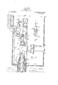
Screwed upon the upper end 'of the pipe 10 and resting upon the cap 9 is a second coupling 24, and from said coupling cap the air chamber pipe extends downwardly, nearly to the lower end of the tube 10, and into the vicinity of the pumping waterlevel as indicated in Fig. le. From the upper end of the coupling cap 24, I extend` theshort nipple 26, leading tofthe standard T' 27 ,i and from the latter, I lead the discharge pipe 2S. Upon the upper openingifi'ffthe T 2T is the gland 29, and through thelinterior of this gland 29, I extend the airlpipe 30, continuing the same down through the'.l interior of the well tubes 8, 10 anti/25 to' the vicinity of the reducing nipplelZ/a'nd at its lower end, I provide the reducing nipple 3l from which extendsa shi/friay sectie/[13] of pipe 32, the lower end ofwhi, jatter pipe is screwed into the diaphr/agrnylf/i, asf' clearly shown. In this manner'y it ,illbbe seen that the upper pipe 10 and thefflwer I.
pipe 22 form chambers separated from' each othery by the diaphragm l5, and that saidl chambers have no communication with each other, except through the valve 19 at' the lower-most end of the pipe 18. Upon the upper end of the pipe I secure the T 33, Aand 'from its lateral opening 34, I extend a pipe to the lower end of the reversing valve 3, as clearly shown in Fig. l1. The upper opening of the T 33 is provided with a gland 36 through which extends the pipe 37 down through the interior of the pipe 30 toits lowermost extremity through the pipe 32, where it is screwed into a by pass 38 in the by pass casting 14 from whichlby pass leads a pipe 39 down to a point somewhat below the upper discharge valve 19.
From the above described piping systcm it will be noted that the pipes l0 and 25 form an'annular`"chamber 40,? closed at the top and open at the bottom. This 'chamber 'forms the air chamber, the purpose of which will be more fully hereinafter explained. In thevdischarge pipe 23, I may, if desired, insert at the coupling l4l what I term a capacity disk, that is to say, a disk or diaphragm located in the discharge opening of the pipe 2S, having a central' aperture therethrough, which aperture has a diameter less than the internal diameter of the pipe 28, so that the capacity of the pumping system may be reduced below the'normalcapacity of the 'discharge pipe 28.` The discharge pipe 28 leads to the closed house -plumbing system, and it is to be understood that such system is normally closed and opened only when water is to be drawn from some one of the reversing valve. This valve consists of the case 41 provided with the upper and lower coupling flanges 42 and 43, theA latter a'ording means for connection with theair pipe 35. Thev interior of the case is divided into several chambers, first, the upper piston valve y.chamber 44 leading to the annular chamber 45, which latter chamber communicates directly with the pipe 2 vleading from the' air receiver 1. `This vannular chamber communicatesy with a cylindrical passage 46 .to a lower air chamber 47. in the center of which islocated van exhaust passage 48,' the latter leading out through the orifice 49'to rthe exterior of the' case. Th'passag'e 4S is y,of the same diameter as the passage 46 and their diameters are slightly less than theV diameter of the upper chamber 44. rThe an- 'nular Achamber 47 is in direct communication'yvith the air pipe35. Located in the chamber 44 and lowerv passage 48 is the spool piston valve 50. This piston valve consists of yan upper head 51 neatly fitting the upper chamber 44, anda lower valve head 52, the latter fitted to the passages 4G Aand 48. 4vThe lower end of the head 52 is slightly conical l as at 53, so as to fit the valve seat 54. Communicating-with the exhaust passage 49 and coupled to the flange 55 ofthe casting 41, is what I term a throttle valve elbow 56 havjlOO ing the passage 57 registering and communii cati'ngwith the exhaust passage 49." The lower opening of the passage`- 57 forms a Y valve seat for the puppet valve 58, the stemr 59 of which extends up tllrough the body of the' elbow, as shown and hasfat its. upperV extremity the'pair of set nut-s 60. Beneath said nuts and bearing upon the .cup 61 is the tension spring- 62. The tendency of this tension spring 62 is to hold the puppet yvalve, 58 upon its seat and thus throttle the-exhaust.A If desired, the throttle elbow 56 may be cnneetedby the pipe 63V with the well curb pipe 8, as illustrated in Fig. l", so rthat in case there should be any vexcessive noise it may be muliled or any water dripv will be discharged directly back into the well.'
Coupled to the upper end of the 'casev41 through the'ilange 42 is the supplemental piston valve case 34. This latterV case' is'provided with the upper piston and-valvecham# ber 65 and the lower valve lchamber 66. The lower' chamber 66 is formed .counterboring the lower-end of '64, screwthre'ading Athe same for a considerable Vdistance and then inserting'the screw -threaded thimble 6T therein. This thinible 6T is provided with a .central aperture. 5S, so as to form a communication between'the chamber 66 and the ,i Til@ .eiesed *mlhreede 'i8 passes es T8 is profe i le rioiible clamp e energemem 8 siie of ehe epeexene epwereliy "iene-e iles est its upper rgering "ieliee'er beers ef fiile Cep l ring S3 is to Y iiras uppermos posiion reemen S1 upon ihe i :rie oep The tension of 7 o3 and the set B4 screwing the of the cap S0, as rom the chamber 1 ieee passage suopiementel ifi r en eve siiownin Fig. 5, f *will heree'er proceed to 1 71 ,J s i n 21 41 @es i er., me insurge and fvied pessege 88 said w pese che exhaust passage i9 up e n sarei pesage eny- 1^eve neeinter be regulated me in er eo eereese er of sei@1 passege, 1 also sure Wili vee gradnely dissipsed through,
there is pressure Within seif vfesse e 38, seeh pressure W111i he equaiized in to. exheus pas:l f 119 ai; the iower end im e #heuse e else in he Chamber beeween the and 76, and die .ser e irme suoi ,ores
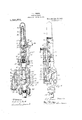
rEhe reguiting faire "1' shown in vertieei cross section in Fig. 2 is as heretofore steced, ioeeie in the :gir pipe 2 leading from the air receiver so he reversing valve. This Valve Consists essentially of the lower cast ing 100, the inermeiiiaite casting 101 the upper casting 102. The lower casting s provided with ehe two chambers 103 en@ roe, ing therein the passage 10S. The upper side oie the diaphragm 105 is formed into e faire seat 107. Upon the upper side of the casting 100 is secured by means of the iange bolts 108, the Casting 101, said eesing 70eing provided with the valve Chamber 109 opening into the chamber 103 and separated sherefrom by means of Gau'ze screen 110. XVthio, the chamber 100 is located the holow valve plug 111 the ioWe-rjend of which yis provied with the esher peeking 112, o
The upper side of Leading from separated Voy the Eliephregm 105, hev- 15 to the central portion of the diaphragm 124 in the residence or' other building.
Having now fully described the 'structure ofthe various parts of my improved pumping system, I will pow proceedto describe its operation. It will be understood lat the beginning that thewell. is comparatively deep and its upper 'end is sulicieiitly enlarged as at 137 to receive the parts of the structure illust-ratedv in Fig. lh, and that said enlarged' upper end `Of the well is covered withv the cover 138, whilel' the pipes 2- and 99 lead laterally to the air reservoir and .parts contiguous thereto above the ground level, such airreceiicr being usually located It is also to be understood that pressure in the reservoir 1, is to be maintained at a coin- 'paratively high point and that the degree of such pressure will be registered upon the gage `With the valve 5 open, air pressure will be admitted into the chamber 103, where it will pass beneath the valve 111, and
- if there is normal air pressure in the chainber 109, said valve will be raised from its seat 10T, and such pressure will pass from Vthe chamber 103 into the chamber 104- and thence along the pipe 2 to the annular cham ber 45 of the reverse valve, thence it Vwill pass down through the passage 47 through pipe 35, thence through the by pass casting 14 to the liquid chamber formed by the pipe 22. Normally the lower end of thel pump tube should be immersed to a depth substantially as indicated in Fig. 1c. Under v `suchconditions the water will find its level Y in thevinterior of the lower liquid chamber 22, through the valve 23. The air pressure coming down through the pipe 30 and through the by pass casting 14, exerts itself upon the surface pf the liquid in the liquid chamber 22, with the result that the liquid or water lis forced up thro-ugh the interior pipe 20 past the valve 19 into the pipe 18, thence through* the by pass casting 14, and tothe upper pump section 10, and within the chamber-.40. As above. described, this inner. tube 25 is in direct communication with the discharge pipe 23 through thel T 27. As the water or liquid is 'forced up through'the upper pump section, the air in the annular chamber -40 formed by the pipe 25 and the pipe 10 is trapped in such a manner as to form 'a compression chamber. At the beginningythe discharge pipe 2S leading tothe yhouse plumbing system is left Open until a solid column of.A water fills the dis- `charge pipe 28, and alli-of the/various pipes in the house plumbing system. lWhen the level of the water within the lower liquid chamber 22 drops below the lower extremity ofr the pipe 39, which of course takes place only when some one or more of the faucets eonneetedswith the house plumbing system is open and the' pressure in the dischargev `pipe 2S correspondingly' lowered, the excess of pressure in the liquid chaniber 22` will force the water" upwardly through the pipe 39, the by pass 3Sl`and the pipe 3T to the the lower en d of the Apipe '39 and lbubbles of i25- and as'tliey approach 'the top, will drive the Y air will shootlup through this water column superpeseifl water ahead and not only produce a water hammer" diminish the head and over-balance the preseifect but also I-i`i5 diaphragm valve Stlirough the passage 93.
sure on the opposite side of the diaphragm an (ill MO in the water line pipe 20 below the valve 19 and at a point on a level with the lower end of the pipe 39 so that whenever the air pressure in the liquid chamber 22 forces the water level down to or below such aperture 140. the air will have access to the interior of the pipe 20. This air, under the heavy pressureto which ite is subjected, will pass through the aperture 1l() and trickle up past the valve 19 through the Water column to the upper water el'a'un'ber formed by the pipe 10, ln order to prevent the air bubbles from rising' into the water Vdischarge. pipe through the pipe Q5, I provide a delector lll mounting; the same upon the pipe 30 just beneath. the lower extremity of the pipe In this manner, the rising` bubbles will be directed into the annular chamber 40, between ghe pipes 1.0 and 25. In this manner I am able to maintain the normal supply of air in the chamber 20 against any leale ze through imperfect joints.
lt is possible for this means of repleuishing the air in the chamber` el() to supply more air than is necessary for actual practical use, and .in order to disposent any surplus air. that is, more than is rrequired :for maintaining the uniform pressure in the charm ber 40, ,l provide a mail aperture 140 in the side of the pipe'if at a predetermined height above'its lower end, so that when the forced below the aperture 140 the surplus air will escape intothe discharge pipe 28 andv the' pressureV within the chamber 40 will be cr'irrespondinglyreduced. Immedia tely upon venting the chamber 40 through the aperture M0 the level of the water in said chamber will rise until equilibrium is again restored. When water is drawn from the discharge pipe '28, it might be thought that the air pressure in the chamber 40 would not operate to continue the discharge ot water after the level in the chamber 40, has passed below the laperture l'l-O. This is not the case. for the reason. that when water is drawn 'from the discharge pipe '28, it is under what may be considered two heads of pressure,'namely, that in the chamber' l0 and that which comes through the pipe. into ilu liquid rhamber 22. (loir sidcrabledra tis ol' water may be taken 'from .to form thevg'oose neck 9F.
Water level within the chamber Ll0 is y will have had time to escape through the aperture 140', so that, practically the entire; length of the pipe 25 may be utilized es a compression air chamber..
ln order to insure suilicient Water friction in the pipe 94, l have, as above indicated,
interposed the Water seal orloop 91k' in the pipe 9i. Under ordinary circumstances, Where the water lift is not too high, l find that this means affords suilicient Water friction in the pipe 91. It may be desirable hoveever, under certain circumstances to provide additional means of producing friction in the pipe 9-land to this end, I may interpose a trap substantially as illustrated in Fig. 6. In this case the pipe 94 enters the upper end ot cylindrical chamber .Qi-l2. The lower end ot' this chamber receives the lower section of the pipe 9i and such pipe extends up into the chamber 9&2 vit'or a considerable distance. and then is turned back upon itself At the very uppermost part o1c the turn in the goose neck 9F.' locate a` minute vent as 94E. This trap serves the' same purpose as the tloop 94C" and its action is substantiallyvas follows:
The surplus or overflow of `vvater from the valve ST. it Will be remembered must be disposed of, and yet it must loe retarded in its discharge. In Fig. lb the structure is shown as depending solely upon the friction of the Water in the pipe 94. l'n Fig. 5ya to add to this friction and form a Water seal'. the loop 9i, is inserted, but Where increased friction' is desired. the structure in Fifi. S is used. lVater from the pipe .fl-t yis dis charged into the chamber 91552. This chamber being hermetically sealed otherwise than by way of the inlet pipe 9st and the discharge goose neck 94, the air which the chamber contains must. upon the accnmiila` tion et 'water therein. find an outlet through a small vent ll-P. No siphoning action ot the goose neck however, takes place until water has`K accumulated in the chamber toa height above,the upper turn of the goose nec; 94, at which point the accumulation" place the registering gage 14.2 in the pipe 955?.
'lhi's` gage, it will be noted7 will register all ol' the tinctu ations of the pressure 1n the die i'charge pipe 28, which of @ourse 'means the waei pressure in jhe house plumbing system above ground.
' 7" e nteipesiion of the regulating vaise is is? the purpose of shutting @if the air imm the L.ir ieeeiver l, from the system at times when excessive nos mede upon the discharge pipe im example, ai' i I@ is a fact 'n sii isolated pair fins; sysems, i is oir: es" he g( aces frequeniy occur and it is in order te lesxiil the sil in ghe res-elseif and prevent its slow leak-age, by wsj! of he pipe 2, beyond the regulating vave T and the discharge'passnge 49 to *che eriisust vent 90, through imperectiy operate@ Wives or the like. t such times t ie pressure in the house pumbing m' closed service sipes Wiii be maintained by the accumulate@ psessue in ibs ail* c zamber 4.0, and inasmuch as the We.- iei in die house plumbing system is -'apped above the waive liv), such piessme wil meet sigii 0i' even ordinary drafts upon the same. vwhen however, suele drafts are suicent te reduce the ee ef the amies in the lower iiqwd chamber Q2 below he lower end of the pipe 39, then the eufvmate action, ss he'etofei'e described Wi'i take place, and the supply of air under pressure Win' again be admitted to the system, The puipese of the.
zeguating miie T is so stop nii the ai? from the pmipng system after the same has been supji'iiec with en initia charge and then permit hnl charge to be exliiausied to e, Certain pein. men s, new charge of is aclfrfzited to the' system freni the receiver n this manner, the air receive?, into which gees the principal cos; of masenance, is iseated from the pumping sfsten: exsep at times when the nii -in said sysem nees repienismng, Y
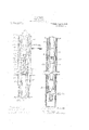
As hitherto describe, pumping system is sppiieabie to weils of erimm'y el medium deph; but in Order te adam is se weis of Hreuei' depth, nd it admsebieto eevse he 'fmu the WGH .by ssges sn for shut Tensen he duplex form, ns iustmted in Fig: T is use-d.' In this ease is necessary also to siightijf modify the reversing vaive 3, se that for tiieduplex system the veves 31 and 32 :me se intereonneced es to sperate atemate y. In Fig. 7 the ai? receiver l, the ,gage 1, globe vzxive 5, cut QE valve 6, eguating valve 7, and rthe pipe 99 with its gege 142, are the samein purpose and alraiigemens as shown in Fig. 15. n pieetiee nd i avisebie o provide a safety Vaise i60 at the receiver l so preventVeveichgaigiig the receiverE The pipe 2 is ie frein she above descibed parts to a T 161, seid being connected as sum'n in 7 An the pai? of regu-'- valves are in the mein seme es the remi,
iaing 'i/'eve shows d of moei wss fr@ i v 1 w Gemes,
"N valve su valve 31 m61 seme es i Fom 'Ehe J charge pine This sans is may isili; deseribeiin ceA 40. FHL@ CD ead the pipe the house pim The exilim 32 leaiis iiA the cir Valves 81 fn exhaust Wiil mises.
Reerrii'ig the reversing imdes-endmg fee @per theuppef: per?. its axis hzeuhn s. ,s sets upon she iowe v practice however, the shown in 7. The i r she lower' cest-ing si', egeiex Wiki valve, ports sind passages ihesein, is ientieai in 'all respects Wish th shows in emmeeiou "2O with Fie. 3, so that fates? tion 0x" saisi pelis is deeme unA f Secured ze she lippe; "s is tiles/*sive missing nis Y A: ,i curing me?! se by cf venieit 3125 for example, 'by means si the bei N53 passing rusugh e mge of msing C inte the sge 41m of i 4l. lower end s the casting cmmterbored a0 :form e ehembez 36 mso the lower end of which is screwed the cap 67 centrally apcrtured as at 68 to form a communication between the chamber 66 and the chamber alle?. The valveseat 69 is provided in the upper end of the chamber 66 for the receptiono'lf the puppet valve 70, said valve being guided by means of the stem 71 in the casting 6ft as shown. Directly above the puppet valve TO is located the small chambcr'l and leading from it is an exhaust passage to the open atmosphere. The stem 71" 'projects into 'an opening 65 which opens laterally outside of the casting.
The spring 7s', located Within this chamber 66 serves to hold the puppet valve 70" upon its seat. y
Adjacent to the opening 65 1 locate the vbell crank lijl with one arm thereot` project ing'y into the chamber 65 for contact With theuppcr ,end oi the valve stem 71. vA corresponding bell crank 165 is connected to the twin reversing valve in identically the same manner and for the same purpose. 'lrhese bell cranks 164 and i6-5 are connected together by the rod 166 so vthat they operate in unison but in opposite phases; that is to say, when the inwardly projecting arm of the lever 16% swings down to depress the valve the corresponding inwardly pr0- jecting arm of the bell crank 165 is raised to permit the seating of the corresponding puppet 'valve in the other reversing valve mech anism, and vice versa. ln order to prevent accidental displacement 01' this toggle link and lever arrangement, I provide a collar 167 upon the middle portion of the link 166, said collar being V shaped in cross sectioii, for coperation with the V shapedspring snap 168, which is secured in place by means of the bolt 162. From this construction it 'will be seen that the toggle lever and link mechanism will shift so that the collar 167 will. first be upon one side of the spring snap 168 and then upon .the other, the spring serving as a yielding means for preventing accidental shifting o'l the parts. i
T he casting Gel is provided with an upper chamber 652 for the reception of the piston 76". |lhis piston'is slightly different from the corresponding piston illustrated in Fig, 3, inasmuch as it is provided with a valve 762 Lpon its upper end 'for coperation with the valve seat 762, the purpose'oi' which will be hereinafter 'fully described. The piston 76" is fnrther provided with a. depending stein 764 which passes through an aperture in the casting and extends into the chamber G5 in position to engage the-inner arm of the toggle lever 164. l provide the chamber 652 with a lateral discharge or exhaustopeningffl to correspond with the passage 88 ol'l the valve shown in Fig. fl. shown this openingy as connected across to the corresponding'lp in the reversing valve 32, by 4means oil th pipe 882 with In Fig. '7 l have chamber 652 4and is provided at its upper end with a pair of adjusting set nuts 82 for the purpose .of adjusting the tension of the spring 88 in exactly the saine manner as the corresponding parts illustrated in Fig. 3, are operated. The upper' end of the chamber i352 is closed by the casting in which the valve seat 7 63 is formed. The valve 762 is for the purpose of closing od the chamber 652 from the pipe 86". vReference to Fig. 7 will show that the'pipe 37 is coupled directly with the pipe 86 and that in the pipe 86 l have located a T 862 with a drip pipe 862. Thecorresponding pipe 864 leads into the valve 87 which as above described is in all respects the same as the .diaphragm valve.
- 87 illustrated in Fig. 5. 4
lt is to be understood that each of the valves 31 and-32 may be provided with a side passage 88 leading from the exhaust passage 49 up to the upper castings 64 in the same manner as is shown in Fig. l; butin such case, I would dispense with the pipe 882 and l its connection with theexhaust T 56. I prefer however, in the duplex system to omit said side passages 88 from the valves 32 and 82,'and use as asubstitute, the pipe 882 with a. connection 88 tothe T 56 and locate in said connection a needle valve 'as 89 for throttling the retained two pounds of pressure from the exhaust T 56. The latter construction is solely for the purpose of reducing the number of parts Ato be looked after vand adjusted.y This duplex system operates as follows: Air pressure is admitted from the receiver 1, through the regulating valve Ffto the T 161 Where it is admitted to the chambers Within the valve casting 41 to operate ein substantially the manner described jffcln vconnection with the reversing valve illustrated in Fig. 3. It must be un-V l Vderstoodljthat one or the other of the puppet valves 70 of the reversing. valves 31 and 32- Awill be unseated thereby permitting the corresponding upper chamber 44 to be vented through the orifice 68 and the exhaust open` ing 73. fAt such time the spool valve corresponding to thc valve' 50 will be raised so as toexhaust the corresponding liquid cham- .beroi-TZQ In the position of `thepart shown in vFig. 7 the lower chamber 22 is beinglexhausted of its air through the correspondingI pipo and reversing valve 31.
This will permit fin ogiun of Water from thel finto the lower chaml.ly with this operation puppet valve 70" in the well past the valve 23. bci-22. Simultaneo. the correspbnding l i reversing 1 lated pres e in the corresponding chamber ve 82 is closed and the accumu- :trav
except by way of the upper liquid chamber i 222 and its discharge pipe 182. Moreover, I
iind that the method ab'oyaedescribed for rel plenishing the tank 2S2'w'ith air, by way of .y the pipe 372 and the small vaperture1402,is4
adequate. AIdovveven'in casethe two stages are separated, as in the case of their o erat-f ing in separate wells, I may if desire provide an aperture in the short section of pipe below the valve 19 corresponding in all re. spects to the aperture"1402in the pipe 202,- so that this replenishing of the chamber 282,
by the means illustrated, wouldA be substanftially, the same; but such a structure would be'substantially the same as that illustrated in lconnection with Figs. 1b, le, and 1d, and the two wells wouldieach have a duplicate of that structure. The duplex 'reversing valve in such atwo well system would be substantially the same as that illustrated in Figs. 7 and 8, except that each of the valves 31 and 32 could be provided withthe diaphragm valve'87'.
exhaust passage therein, v,with a throttling valve in said exhaust passage. y
4. In a pumping system, the combination ot' a source of fluid pressure supply, a source. of liquid supply, a liquid chamber, a valved'inletcnnection from said liquid supply :tu
said chamber, avalved and normally closed.v
discharge pipe leading from said` chamberl to av level higher than` that of said` liquid supply, .a reversing valvefor admitting pres-l sure supply to said liquid chamber, saidv valve actuated by differential pressure from said -fluid pressure'supply 'to exhaust said I have not' shown'the two drip pipes 863i and 945 asconnected back to the well,'but
it shouldbe understood that 'these pipes may be'co'nnecte'd back so as to discharge into the well in the same manner as the pipe 94: shown inl Fig. 1b, iflde'fsired. These changes of'partsto meet diilerent conditions in-practice, I'do'nnot regard as modifications in any respect, but consider them as .partand parcel yof the entire 'structure andy to be used as and where conditions may require.
I claim,
1. In a pumping system, the combination of a source of fluidpresgure supply, a liquid chamber having inlet and discharge valves,
'a reversing valve for admitting liuid pressure from said supply to said chamber,` and i for exhausting said pressure therefrom, and
meansfor thrcttling the exhaust from said liquid chamber.
2. In a pumping system, the combination of a source of fluid pressure, a liquid rhumber, inlet and disg'arge valves4 for said chamber, a rcversi'g valve for admitting pressure from said-'supply toand exhausting the'same from said liquid chamber, and a differential pressure` operated means actu ated by thev lowering of the liquid in said ,liquid chamber to admit said fluid pressure to and for actuating said reversing valve to ehlmff't the Pressure from said liquid Chim? zIn afpumping system, thev combination vuree of fluid pressure supply and a .offliquid supply, a liquid chamber, a ,inlet connection between said chamber said-liquid supply, anormally closed barge.- pi'pe leading from said chamber, uerfsing valve'or admitting fluid presjfrcmaid'uid supply to` said liquid fluidfpressure fro'msaid liquid chamber, and
means for creating said differentialof .pres-l sure for actuating saidreversing valve.
5. In a pumping system, the combination of a' liquid chamber having a valved inlet and a valved discharge pipe, a reversing valve'for introducing air pressure to and exhausting the saine from said chamber,
and means for actuating said valve operatedA .Y by a differential. of pressure between sald A discharge pipe and said liquid chamber.
6. In a pumping system, the combination of a liquid chamber, a valved inlet and a valved and ,normally closed dischargepipe for said chamber, a valve for exhausting the vpressure from said chamber to cause an in- Vhausting 'pressurp from said chamber to cause'arrise of liquid'therein, and for admitting pressure thereto to cause a vdischarge of liquid therefrom into said discharge pipe, means comprising a diaphragm valve operated by a differential of pressure 'between said discharge pipe and said liquid chamber 'ico' 'to admit accumulated pressure from said liquid chamber 'to actuates aid reversing fjsaidreversing valve having an ing said severlal passa valve.
8. In .a pumping system, a valve, means for permitting'fluid pressure to actuate said valve to admit such ressure to the pumping mechanism, and di 'erential pressure actuated mechanism or operating said. valve to exhaust said pressure from said pumping system anda valve' for throttling the exhaust of said pressure from said system.
9. In a pumping system, a reversing valve comprising a valve case havingfinlet, discharg and exhaust passages therein, dit# ferential piston and valve( chambers connectges,\a di`erential plis# mesme valve, greviy ineens for eeueting ssi Valve to admit fluid pressure se she pumping system, a i'erenialpz'essua'e "nissen connected to said Vave to? seieesmg ecenmnaied vpressule upon the sife seid piston,
to cause the seme te somete seidirss named valve and thereby exheus; the' pressuie fem seid system, and means is? ieeeining p01- tion of the pl'essure wihin seid syseema l1.Vv In a pumping sysem, the eeinbinatien lof e source of uid pressure suppyi e liquid chamber having inlet engl disehsge velues, a reversing velue AIci" ,admitting jiessure from said supply te seid chamber end exhausting seid pessuie zheeffrom, means 'fon autnoznaticaiy eguieting the admission of inici' pressue'e frenz/said suppy en vsaid. lreversing valve; and "means for threw-ling the exhaust freni seid ii'quid eheinbei'.
12. n a pumping system? the cembuetion o' e source of iui piessuie suppiy, siiqui ehamber having inlet and discharge veines,v e reversing vahe :50e adnii'ing piessuie Ifrom said supply te said enembennd iter exheusing sei piessuie herefrnm, mee-ns for retaining the eziheus?, zem seid liquid diamine? and meses for utilizing the reerded exhaust ere ire fer z'emding the :www ion of said Fevesing sive ze ienfimit eressure to saif eilen i3. In e pimpin iena? 'iie combine'on of e source of iuid piessuie suppiy, a iquid Chamber having inlet sed iseimrge veives fer sid diamine; s reversing Vaise for ed Initing pressuie from saic supply to and exhausting lie same from seid iquid Chaniben means for ne exhaust from said ehembei and mei is im? utilizing said i5. Les pumping syssenz, e Jdi''eentiel ,pressue and gfeviy ee-ueteci veiffe eem prising e veve cese e pressure niet perf, and en exhaust outlet ser/'ice pipe emi s valve cheminee lziiee i5. s vulve in said chamber in pew le normali? 7@ close the seme from "Il i peut, whereby pressu'e may gradually chamber above s-'elve x equalize the pressure there@ r 10W said valve, (i. i'esiictefi i is eh 7.5 from seid ehem/ber seid vaine, s pegpetfveive ebntoliing seid exhaust por; euri di'erenfia pzesszue eeeee. me ism operating seid puppet vsiye te e exhaust port, "whereby geed se ei: `seid reveisiig veve uri. peiilnen simutzmeensiy pipe eo saiVi-esmnsf33ers g s s umili pressure end gevitj' n- S5 pipe and e 'vei've Q: seid ehembe in a pesitien ehe seme from said if se by pressue may" geduelf ,eid e isi equuize pressuleeheiiein w ie-e" velue. e restzieteci euh-euse pei-. ilo? ssii abofe seid nave, e veine cenere fi, 1 `L L l ML' u e sind emeusi.. peice es i diifeie mei piesssie eetuee-neehsnism 'e: epei :i 2g' seid @et valve )zo epen'seiu by a greduei @peres-ion ei @sive wii nisse said ine neessiy open seid hause pm, means c'esing of sei puppe* 'e i s i ising a ez ne .A pot and esiiese es* pipe and. e Juive eiieinnei1 seid chemins? in e pesi .u the same from i '1 by pressure me be? shove v the piessui'e therein e, vaive, e est'iieteci esili chamber above seid wei-fe Controiiing said exssus p tie pressure zictusteci mechanism *en ating' said puppet valve te @pen se' ik pori whereby e gradual e reversing miv-e will Giese seid iifel simultaneously open seii seiufiee said exhaust inert?, time i necei te sein exhnusf-v peril ei "e portion of the pessiue 'Within pipe. f
18, n e puin-ning sysem, iii
ne and 120 means for admitting fluid pressure from 'said supply to said chamber and for exhausting said pressure therefrom, va 'discharge pipe connected With said discharge valve,and a compressed air -chamber asso-v ciated with said discharge pipe for maintaining` substantially a uniform pressure upon the liquid in said discharge pipe and means for automatically re lenishing vthe air in said chamber from sai fluid pressure Supply- 19. In a pumping system,"the combination of asource of iuid pressure supply, a liquid chamber having inlet and discharge valves, 15 means for admitting iiuid pressure' from hausting said pressure therefrom, a, discharge pipe conreted 'with said discharge valve, and a compressed air chamber associated with said discharge pipe'for' maintaining substantiallya uniform pressure upon the liquid in said discharge pipe,I and' means for replenishingthe air in said compressedair chamber-from said liquid chamber, for maintaining the pressure in' said compressed' air chamber againstleakage therefrom.-
20. In a pumping system, 'the combination of a liquid chamber, a valved inlet and a valved discharge pipe for ,said chamber, a valve for exhausting the pressure from said vchamber to cause 'an influx of liquid thereto "through said valved inlet, and. for. admitf ting fiuid pressure to said. chamber to cause the discharge of 4the liquid therefrom, a compressed air chamber connected with said discharge pipe, and means for admitting compressed air .from said liquid 'chamber to said compressed air chamber by Wayvof said valved discharge pipe, for maintaining the pressure in said compressed air chamber against leakage therefrom. v 1 Y. l 21. In a pumping system,the combina'- tion of a source'of fluid pressurel supply, a plurality of liquid chambers each having inlet and discharge valves, a plurality of reversing valve'sfor admitting fluid. pressure from said supply to said chambers, and for exhausting said pressure therefrom alternately, 'and means for 4throttling the eX haust, from said liquid chambers.
22. Ina pumping system, the combination of a source of fluid pressure supply, a plul rality of liquid chambers each having inlet and dischar e valves, a reversing valve for eachof sai chambers for admitting pressure from said supply to and exhausting the same from said liquid chambers alternately,
and a differential pressure operated means Y'Q0 actua-ted'by the lowering of the liquid in said i 1 liquid chambers to admit said fluid p'ressure Y to and for alternately actuating said reversing valves respectively to'exhaust the pres-y V-. sure4 from said liquid chambers. y
' li.- 23. i'.-Iu' u pumping systemthe combination said supply to said chamber and for eX-V of a source of iiuid pressure supply, and a source of liquid supply, a. plurality of liquid chambers, valved vinlet connections between 4each of said liquid chambers' respectively and said liquid supply, a vnormally closed discharge pipe leading from each of said chambers, a reversing val vefor each of said liquid chambers foradmitting fluid pressure frein said Huid supply to said liquid chambers respectively, said reversing valves each having -an exhaust passage therein leading to a common exhaust discharge, and a throttling Y valve in said ezihaust discharge.
24. In a pumping system, the combination of a source of fluid pressure supply, a source of liquid supply, a plurality of liquid chambers, 4valved inlet connections from said liquid suppl7 to said chambers respectively, a valved an normally closed discharge pipe leading fromsaid chambers to a level higher than that of the liquidsupply, reversing valves for admitting pressure from said preure supply to said liquid chambers respectively and alternately', said valves actuated by', differential pressure from said fluid pressure supply to exhaust said pres- 4- sure from said liquid chambers respectively,
and means for creating a dierential of pressure for actuaing said'reversing valves.
25. In a pumping system, the combination of a plurality of liquid chambers each hav' ing'a valved inlet and a valved discharge pipe, a reversing valve for each of said liquid chambers for alternately introducing air pressure to and exhausting the same for actuating said reversing valves operated Vfrom said chambers respectively, and means l by a differential of pressure "between said cause an' influx of liquid thereto through.
said valved liquid inlets` and for permitting y lliquid pressure to said chamber to cause a Q.
discharge of liquid therefrom, and means actuated by the differential of. pressurev between said discharge pipe and Asaid liquid .y chambers for actuating said valves toeX- haust said liquid chambers alterantely.
27. Ina pumping system, the combilia'- tion of ja plurality of liquid chambers, ya .y valved inlet and a normally closed discharge pipe having a valved connection with and for each of said liquid chambers, al valve for each of said liquid chambers for exhausting pressure therefrom to cause a rise of liquidr therein, and for admitting pressure theretov to cause a discharge of liquid therefrom into. said discharge pipes means for actuating said valve' operated bix/:a differential of pres-
Priority Applications (1)
| Application Number | Priority Date | Filing Date | Title |
|---|---|---|---|
| US68068412A US1136070A (en) | 1912-02-29 | 1912-02-29 | Pumping system. |
Applications Claiming Priority (1)
| Application Number | Priority Date | Filing Date | Title |
|---|---|---|---|
| US68068412A US1136070A (en) | 1912-02-29 | 1912-02-29 | Pumping system. |
Publications (1)
| Publication Number | Publication Date |
|---|---|
| US1136070A true US1136070A (en) | 1915-04-20 |
Family
ID=3204176
Family Applications (1)
| Application Number | Title | Priority Date | Filing Date |
|---|---|---|---|
| US68068412A Expired - Lifetime US1136070A (en) | 1912-02-29 | 1912-02-29 | Pumping system. |
Country Status (1)
| Country | Link |
|---|---|
| US (1) | US1136070A (en) |
Cited By (1)
| Publication number | Priority date | Publication date | Assignee | Title |
|---|---|---|---|---|
| US4818187A (en) * | 1986-05-21 | 1989-04-04 | Daniel Scampini | Fluid exchange pump |
-
1912
- 1912-02-29 US US68068412A patent/US1136070A/en not_active Expired - Lifetime
Cited By (1)
| Publication number | Priority date | Publication date | Assignee | Title |
|---|---|---|---|---|
| US4818187A (en) * | 1986-05-21 | 1989-04-04 | Daniel Scampini | Fluid exchange pump |
Similar Documents
| Publication | Publication Date | Title |
|---|---|---|
| US1136070A (en) | Pumping system. | |
| US1942598A (en) | Expansion head | |
| US1814857A (en) | Controlling apparatus for conduits | |
| US1754946A (en) | Well-flowing apparatus | |
| Lescovich | Locating and Sizing Air‐Release Valves | |
| US2634680A (en) | Pump | |
| US984329A (en) | Pumping apparatus. | |
| US1682336A (en) | Robert hentschel | |
| US2566295A (en) | Hydraulic pumping jack | |
| US1600385A (en) | Pumping system | |
| US2089741A (en) | Valve assembly | |
| US1272625A (en) | Oil-well apparatus. | |
| US1356684A (en) | Pump and pumping system | |
| US1658032A (en) | Pneumatic pump | |
| US1629028A (en) | Steam-condensing and boiler-water-supply apparatus of steam-power plants | |
| US900669A (en) | Pumping mechanism. | |
| US1793119A (en) | Condensing apparatus | |
| US1861843A (en) | Gas lift pump | |
| US650168A (en) | Water-lift. | |
| US1274332A (en) | Pneumatic pump. | |
| US1875440A (en) | Multistage pneumatic pump | |
| US990085A (en) | Subterranean pumping system. | |
| US650167A (en) | Water-lift. | |
| US1724853A (en) | Pneumatic apparatus for pumping wells | |
| US1492963A (en) | Apparatus for treating oil from wells |