US11326473B2 - Bearing assembly and turbocharger including the bearing assembly - Google Patents
Bearing assembly and turbocharger including the bearing assembly Download PDFInfo
- Publication number
- US11326473B2 US11326473B2 US16/719,236 US201916719236A US11326473B2 US 11326473 B2 US11326473 B2 US 11326473B2 US 201916719236 A US201916719236 A US 201916719236A US 11326473 B2 US11326473 B2 US 11326473B2
- Authority
- US
- United States
- Prior art keywords
- outer race
- race
- shaft
- rolling element
- turbocharger
- Prior art date
- Legal status (The legal status is an assumption and is not a legal conclusion. Google has not performed a legal analysis and makes no representation as to the accuracy of the status listed.)
- Active, expires
Links
Images


Classifications
-
- F—MECHANICAL ENGINEERING; LIGHTING; HEATING; WEAPONS; BLASTING
- F01—MACHINES OR ENGINES IN GENERAL; ENGINE PLANTS IN GENERAL; STEAM ENGINES
- F01D—NON-POSITIVE DISPLACEMENT MACHINES OR ENGINES, e.g. STEAM TURBINES
- F01D25/00—Component parts, details, or accessories, not provided for in, or of interest apart from, other groups
- F01D25/16—Arrangement of bearings; Supporting or mounting bearings in casings
- F01D25/162—Bearing supports
- F01D25/164—Flexible supports; Vibration damping means associated with the bearing
-
- F—MECHANICAL ENGINEERING; LIGHTING; HEATING; WEAPONS; BLASTING
- F01—MACHINES OR ENGINES IN GENERAL; ENGINE PLANTS IN GENERAL; STEAM ENGINES
- F01D—NON-POSITIVE DISPLACEMENT MACHINES OR ENGINES, e.g. STEAM TURBINES
- F01D25/00—Component parts, details, or accessories, not provided for in, or of interest apart from, other groups
- F01D25/04—Antivibration arrangements
-
- F—MECHANICAL ENGINEERING; LIGHTING; HEATING; WEAPONS; BLASTING
- F01—MACHINES OR ENGINES IN GENERAL; ENGINE PLANTS IN GENERAL; STEAM ENGINES
- F01D—NON-POSITIVE DISPLACEMENT MACHINES OR ENGINES, e.g. STEAM TURBINES
- F01D5/00—Blades; Blade-carrying members; Heating, heat-insulating, cooling or antivibration means on the blades or the members
- F01D5/02—Blade-carrying members, e.g. rotors
- F01D5/10—Anti- vibration means
-
- F—MECHANICAL ENGINEERING; LIGHTING; HEATING; WEAPONS; BLASTING
- F16—ENGINEERING ELEMENTS AND UNITS; GENERAL MEASURES FOR PRODUCING AND MAINTAINING EFFECTIVE FUNCTIONING OF MACHINES OR INSTALLATIONS; THERMAL INSULATION IN GENERAL
- F16C—SHAFTS; FLEXIBLE SHAFTS; ELEMENTS OR CRANKSHAFT MECHANISMS; ROTARY BODIES OTHER THAN GEARING ELEMENTS; BEARINGS
- F16C19/00—Bearings with rolling contact, for exclusively rotary movement
- F16C19/02—Bearings with rolling contact, for exclusively rotary movement with bearing balls essentially of the same size in one or more circular rows
- F16C19/14—Bearings with rolling contact, for exclusively rotary movement with bearing balls essentially of the same size in one or more circular rows for both radial and axial load
- F16C19/18—Bearings with rolling contact, for exclusively rotary movement with bearing balls essentially of the same size in one or more circular rows for both radial and axial load with two or more rows of balls
-
- F—MECHANICAL ENGINEERING; LIGHTING; HEATING; WEAPONS; BLASTING
- F16—ENGINEERING ELEMENTS AND UNITS; GENERAL MEASURES FOR PRODUCING AND MAINTAINING EFFECTIVE FUNCTIONING OF MACHINES OR INSTALLATIONS; THERMAL INSULATION IN GENERAL
- F16C—SHAFTS; FLEXIBLE SHAFTS; ELEMENTS OR CRANKSHAFT MECHANISMS; ROTARY BODIES OTHER THAN GEARING ELEMENTS; BEARINGS
- F16C19/00—Bearings with rolling contact, for exclusively rotary movement
- F16C19/54—Systems consisting of a plurality of bearings with rolling friction
- F16C19/541—Systems consisting of juxtaposed rolling bearings including at least one angular contact bearing
- F16C19/542—Systems consisting of juxtaposed rolling bearings including at least one angular contact bearing with two rolling bearings with angular contact
-
- F—MECHANICAL ENGINEERING; LIGHTING; HEATING; WEAPONS; BLASTING
- F16—ENGINEERING ELEMENTS AND UNITS; GENERAL MEASURES FOR PRODUCING AND MAINTAINING EFFECTIVE FUNCTIONING OF MACHINES OR INSTALLATIONS; THERMAL INSULATION IN GENERAL
- F16C—SHAFTS; FLEXIBLE SHAFTS; ELEMENTS OR CRANKSHAFT MECHANISMS; ROTARY BODIES OTHER THAN GEARING ELEMENTS; BEARINGS
- F16C25/00—Bearings for exclusively rotary movement adjustable for wear or play
- F16C25/06—Ball or roller bearings
- F16C25/08—Ball or roller bearings self-adjusting
- F16C25/083—Ball or roller bearings self-adjusting with resilient means acting axially on a race ring to preload the bearing
-
- F—MECHANICAL ENGINEERING; LIGHTING; HEATING; WEAPONS; BLASTING
- F16—ENGINEERING ELEMENTS AND UNITS; GENERAL MEASURES FOR PRODUCING AND MAINTAINING EFFECTIVE FUNCTIONING OF MACHINES OR INSTALLATIONS; THERMAL INSULATION IN GENERAL
- F16C—SHAFTS; FLEXIBLE SHAFTS; ELEMENTS OR CRANKSHAFT MECHANISMS; ROTARY BODIES OTHER THAN GEARING ELEMENTS; BEARINGS
- F16C27/00—Elastic or yielding bearings or bearing supports, for exclusively rotary movement
- F16C27/04—Ball or roller bearings, e.g. with resilient rolling bodies
- F16C27/045—Ball or roller bearings, e.g. with resilient rolling bodies with a fluid film, e.g. squeeze film damping
-
- F—MECHANICAL ENGINEERING; LIGHTING; HEATING; WEAPONS; BLASTING
- F05—INDEXING SCHEMES RELATING TO ENGINES OR PUMPS IN VARIOUS SUBCLASSES OF CLASSES F01-F04
- F05D—INDEXING SCHEME FOR ASPECTS RELATING TO NON-POSITIVE-DISPLACEMENT MACHINES OR ENGINES, GAS-TURBINES OR JET-PROPULSION PLANTS
- F05D2220/00—Application
- F05D2220/40—Application in turbochargers
-
- F—MECHANICAL ENGINEERING; LIGHTING; HEATING; WEAPONS; BLASTING
- F05—INDEXING SCHEMES RELATING TO ENGINES OR PUMPS IN VARIOUS SUBCLASSES OF CLASSES F01-F04
- F05D—INDEXING SCHEME FOR ASPECTS RELATING TO NON-POSITIVE-DISPLACEMENT MACHINES OR ENGINES, GAS-TURBINES OR JET-PROPULSION PLANTS
- F05D2240/00—Components
- F05D2240/50—Bearings
-
- F—MECHANICAL ENGINEERING; LIGHTING; HEATING; WEAPONS; BLASTING
- F05—INDEXING SCHEMES RELATING TO ENGINES OR PUMPS IN VARIOUS SUBCLASSES OF CLASSES F01-F04
- F05D—INDEXING SCHEME FOR ASPECTS RELATING TO NON-POSITIVE-DISPLACEMENT MACHINES OR ENGINES, GAS-TURBINES OR JET-PROPULSION PLANTS
- F05D2260/00—Function
- F05D2260/30—Retaining components in desired mutual position
- F05D2260/38—Retaining components in desired mutual position by a spring, i.e. spring loaded or biased towards a certain position
-
- F—MECHANICAL ENGINEERING; LIGHTING; HEATING; WEAPONS; BLASTING
- F05—INDEXING SCHEMES RELATING TO ENGINES OR PUMPS IN VARIOUS SUBCLASSES OF CLASSES F01-F04
- F05D—INDEXING SCHEME FOR ASPECTS RELATING TO NON-POSITIVE-DISPLACEMENT MACHINES OR ENGINES, GAS-TURBINES OR JET-PROPULSION PLANTS
- F05D2260/00—Function
- F05D2260/96—Preventing, counteracting or reducing vibration or noise
-
- F—MECHANICAL ENGINEERING; LIGHTING; HEATING; WEAPONS; BLASTING
- F16—ENGINEERING ELEMENTS AND UNITS; GENERAL MEASURES FOR PRODUCING AND MAINTAINING EFFECTIVE FUNCTIONING OF MACHINES OR INSTALLATIONS; THERMAL INSULATION IN GENERAL
- F16C—SHAFTS; FLEXIBLE SHAFTS; ELEMENTS OR CRANKSHAFT MECHANISMS; ROTARY BODIES OTHER THAN GEARING ELEMENTS; BEARINGS
- F16C2360/00—Engines or pumps
- F16C2360/23—Gas turbine engines
- F16C2360/24—Turbochargers
Definitions
- the present invention generally relates to a turbocharger for delivering compressed air to the internal combustion engine.
- Turbochargers receive exhaust gas from an internal combustion engine and deliver compressed air to the internal combustion engine. Turbochargers are used to increase power output of the internal combustion engine, lower fuel consumption of the internal combustion engine, and reduce emissions produced by the internal combustion engine. Delivery of compressed air to the internal combustion engine by the turbocharger allows the internal combustion engine to be smaller, yet able to develop the same or similar amount of horsepower as larger, naturally aspirated internal combustion engines. Having a smaller internal combustion engine in the vehicle reduces the mass and aerodynamic frontal area of the vehicle, which helps reduce fuel consumption of the internal combustion engine and improve fuel economy of the vehicle.
- Typical turbochargers include a shaft extending along an axis between a first shaft portion and a second shaft portion spaced from the first shaft portion along the axis, a compressor wheel coupled to the first shaft portion of the shaft, and a turbine wheel coupled to the second shaft portion of the shaft.
- Typical turbochargers also include a bearing assembly disposed between the first and second shaft portions of the shaft. The bearing assembly is coupled to the shaft for supporting rotation of the shaft.
- Typical bearing assemblies include a first inner race, a second inner race, and an outer race.
- the first and second inner races have an interference fit with the shaft.
- These bearing assemblies also include a first rolling element disposed between the outer race and the first inner race for supporting rotation of the shaft, and a second rolling element disposed between the outer race and the second inner race for supporting rotation of the shaft.
- Components in typical bearing assemblies are arranged in a configuration where the preloading of the first and second rolling elements is negatively affected by tolerances of the components, particularly by tolerances between the first and second inner races and the shaft because of the interference fit required between the first and second inner races and the shaft.
- the preloading of the first and second rolling elements is also affected by thermal deformation of the components of the typical bearing assemblies because thermal deformation of the components worsens the impact the tolerances of the components have on the bearing assembly. Therefore, the components of typical bearing assemblies fail to maintain sufficient forces on the first and second rolling elements to preload the first and second rolling elements, thus resulting in skidding of the first and second rolling elements.
- the components of typical bearing assemblies exert excessive forces on the first and second rolling elements, thus resulting in premature failure of the bearing assembly.
- a turbocharger is disclosed.
- the turbocharger delivers compressed air to an internal combustion engine.
- the turbocharger includes a shaft extending along an axis A between a first shaft portion and a second shaft portion spaced from the first shaft portion along the axis A, a compressor wheel coupled to the first shaft portion of the shaft, and a turbine wheel coupled to the second shaft portion of the shaft.
- the turbocharger also includes a bearing assembly disposed between the first and second shaft portions of the shaft, and the bearing assembly is coupled to the shaft for supporting rotation of the shaft.
- the bearing assembly includes an inner race, a first outer race, and a second outer race.
- the first inner race is coupled to the shaft between the first and second shaft portions of the shaft.
- the first outer race is proximate to the first shaft portion of the shaft, and is spaced radially from the inner race.
- the second outer race is proximate to the second shaft portion of the shaft, and is both spaced from the first outer race along the axis and spaced radially from the inner race.
- the bearing assembly also includes a first rolling element disposed between the first outer race and the inner race for supporting rotation of the shaft, and a second rolling element disposed between the second outer race and the inner race for supporting rotation of the shaft.
- the bearing assembly further includes a first biasing member coupled to the first outer race.
- the first biasing member is configured to bias the first outer race toward the second outer race and against the first rolling element to preload the first rolling element.
- the bearing assembly also includes a second biasing member coupled to the second outer race. The second biasing member is configured to bias the second outer race toward the first outer race and against the second rolling element to preload the second rolling element.
- the arrangement of the components in the bearing assembly allows for a more consistent preloading of the first and second rolling elements as compared to typical bearing assemblies. More specifically, the arrangement of components in the bearing assembly minimizes the impact that tolerances of the components in the bearing assembly have on the preloading of the first and second rolling elements. In particular, the combination of the inner race and the first and second outer races being biased toward one another by the first and second biasing members limits the impact that tolerances have between the inner race and the shaft.
- the arrangement of components limits the impact that thermal deformation has on the preloading of the first and second rolling elements, thus further limiting the impact that tolerances have on the bearing assembly.
- the arrangement of components in this bearing assembly consistently exerts appropriate forces to preload the first and second rolling elements without skidding of the first and second rolling elements and without risking premature failure of the bearing assembly.
- FIG. 1 is a schematic illustration of a turbocharger extending along an axis A;
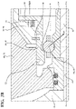
- FIG. 2A is a cross-sectional view of the turbocharger, with the inner race being a unitary component;
- FIG. 2B is a cross-sectional view of the turbocharger, with the inner race including a first inner race and a second inner race;
- FIG. 2C is a cross-sectional view of the turbocharger, with the inner race including a spacer disposed between the first inner race and the second inner race;
- FIG. 3A is a cross-sectional view of the turbocharger illustrated in FIGS. 2A-2C , with the first outer race having a first race surface that is concave;
- FIG. 3B is a cross-sectional view of the turbocharger illustrated in FIGS. 2A-2C , with the first outer race having the first race surface that is planar.
- a turbocharger 10 is shown schematically in FIG. 1 .
- the turbocharger 10 receives exhaust gas from an internal combustion engine to deliver compressed air to the internal combustion engine.
- the turbocharger 10 includes a shaft 12 extending along an axis A between a first shaft portion 14 and a second shaft portion 16 spaced from the first shaft portion 14 along the axis A, a compressor wheel 18 coupled to the first shaft portion 14 of the shaft 12 , and a turbine wheel 20 coupled to the second shaft portion 16 of the shaft 12 .
- the turbocharger 10 also includes a bearing assembly 22 disposed between the first and second shaft portions 14 , 16 of the shaft 12 .
- first shaft portion 14 of the shaft 12 may be near the end of the shaft 12 proximate to the compressor wheel 18
- the second shaft portion 16 of the shaft 12 may be near the end of the shaft 12 proximate to the turbine wheel 20 .
- the bearing assembly 22 is coupled to the shaft 12 for supporting rotation of the shaft 12 .
- the compressor wheel 18 may be disposed in a compressor housing 42
- the turbine wheel 20 may be disposed in a turbine housing 40
- the bearing assembly 22 may be disposed in a bearing housing 38
- the turbocharger 10 may have a back plate 44 disposed either between the compressor housing 42 and the bearing housing 38 , between the turbine housing 40 and the bearing housing 38 , or disposed within any one of the compressor housing 42 , the turbine housing 40 , and the bearing housing 38 .
- the bearing assembly 22 includes an inner race 24 , a first outer race 26 , and a second outer race 28 , as shown in FIGS. 2A-2C .
- the inner race 24 extends along the axis A and is coupled to the shaft 12 between the first and second shaft portions 14 , 16 of the shaft 12 .
- the first outer race 26 is proximate to the first shaft portion 14 of the shaft 12 , and is spaced radially from the inner race 24 .
- the second outer race 28 is proximate to the second shaft portion 16 of the shaft 12 , and is both spaced from the first outer race 26 along the axis and spaced radially from the inner race 24 .
- the bearing assembly 22 also includes a first rolling element 30 disposed between the first outer race 26 and the inner race 24 for supporting rotation of the shaft 12 , and a second rolling element 32 disposed between the second outer race 28 and the inner race 24 for supporting rotation of the shaft 12 .
- the first rolling element 30 of the bearing assembly 22 may be a first ball bearing 68 .
- the second rolling element 32 of the bearing assembly 22 may be a second ball bearing 70 . It is to be appreciated, however, that the first and second rolling elements 30 , 32 may be any number of geometric shapes, including cylindrical, and may be bushings or roller bearings.
- the bearing assembly 22 further includes a first biasing member 34 coupled to the first outer race 26 .
- the first biasing member 34 is configured to bias the first outer race 26 toward the second outer race 28 and against the first rolling element 30 to preload the first rolling element 30 .
- the bearing assembly 22 also includes a second biasing member 36 coupled to the second outer race 28 .
- the second biasing member 36 is configured to bias the second outer race 28 toward the first outer race 26 and against the second rolling element 32 to preload the second rolling element 32 .
- the arrangement of the components in the bearing assembly 22 allows for a more consistent preloading of the first and second rolling elements 30 , 32 as compared to typical bearing assemblies. More specifically, the arrangement of components in the bearing assembly 22 minimizes the impact that tolerances of the components in the bearing assembly 22 have on the preloading of the first and second rolling elements 30 , 32 . In particular, the combination of the inner race 24 and the first and second outer races 26 , 28 being biased toward one another by the first and second biasing members 34 , 36 limits the impact that tolerances have between the inner race 24 and the shaft 12 .
- the arrangement of components limits the impact that thermal expansion has on the preloading of the first and second rolling elements 30 , 32 , thus further limiting the impact that tolerances have on the bearing assembly 22 .
- the arrangement of components in the bearing assembly 22 consistently exerts appropriate forces to preload the first and second rolling elements 30 , 32 without skidding of the first and second rolling elements 30 , 32 and without risking premature failure of the bearing assembly 22 .
- the arrangement of components is configured to exert a first force against the first rolling element 30 .
- the arrangement of components is also configured to exert a second force against the second rolling element 32 .
- the first force is in a direction, for example, the first direction D 1 as shown in FIGS. 2A-3B , to preload the first rolling element 30 .
- the second force is in another direction, for example, the second direction D 2 as shown in FIGS. 2A-3B , to preload the second rolling element 32 .
- the first direction D 1 that the first force may be configured to be exerted in may be both radially toward the shaft 12 and axially toward the second outer race 28 . In other words, the first direction D 1 is essentially conical, as shown in FIGS. 2A-2C .
- the second direction D 2 that the second force may be configured to be exerted in may be both radially toward the shaft 12 and axially toward the first outer race 26 .
- the second direction D 2 is essentially conical, as shown in FIGS. 2A-2C .
- the first direction D 1 and the second direction D 2 intersect to define an “X” shape.
- the first direction D 1 and the second direction D 2 that the first and second forces are configured to be exerted in, respectively are both axially and radially inward with respect to the axis A.
- the first and second biasing members 34 , 36 exert the appropriate forces to preload the first and second rolling elements 30 , 32 . More specifically, the first biasing member 34 exerts a first biasing force against the first outer race 26 substantially parallel to the axis A and in a first biasing direction BD 1 . Similarly, the second biasing member 36 exerts a second biasing force against the second outer race 28 substantially parallel to the axis A and in a second biasing direction BD 2 .
- the first and second biasing members 34 , 36 may be coupled to at least one of the bearing housing 38 , the turbine housing 40 , the compressor housing 42 , and the back plate 44 , among other options.
- the first and second biasing members 34 , 36 may be springs, particularly coiled springs or wave springs.
- the first outer race 26 has a first race surface 46 angularly tilted relative to the axis A that is in contact with the first rolling element 30
- the second outer race 28 has a second race surface 48 angularly tilted relative to the axis A that is in contact with the second rolling element 32
- the first race surface 46 is configured to exert the first force against the first rolling element 30 in the first direction D 1 to preload the first rolling element 30
- the second race surface 48 is configured to exert the second force against the second rolling element 32 in the second direction D 2 to preload the second rolling element 32
- the first force may be exerted either partially or completely circumferentially about the axis A
- the second force may be exerted either partially or completely circumferentially about the axis A.
- the first biasing member 34 exerts the first biasing force in the first biasing direction BD 1 against the first outer race 26 .
- the first race surface 46 of the first outer race 26 redirects the first biasing force in the first biasing direction BD 1 to the first force in the first direction D 1 against the first rolling element 30 to preload the first rolling element 30 .
- the second biasing member 36 exerts the second biasing force in the second biasing direction BD 1 against the second outer race 28 .
- the second race surface 48 of the second outer race 28 redirects the second biasing force in the second biasing direction BD 1 to the second force in the second direction D 1 against the second rolling element 32 to preload the second rolling element 32 .
- the first direction D 1 that the first force is configured to be exerted is both radially toward the shaft 12 and axially toward the second outer race 28
- the second direction D 2 that the second force is configured to be exerted is both radially toward the shaft 12 and axially toward the first outer race 26 .
- the first direction D 1 and the second direction D 2 may intersect to define the “X” shape.
- the first direction D 1 and the second direction D 2 that the first and second forces are configured to be exerted in, respectively are both axially and radially inward with respect to the axis A.
- first and second race surfaces 46 , 48 are concave.
- FIG. 3A depicts the first race surface 46 being concave.
- the first and second race surfaces 46 , 48 are planar.
- FIG. 3B depicts the first race surface 46 as being planar. It is to be appreciated that the first and second race surfaces 46 , 48 may be of any geometric shape, including convex and polygonal, among other possible shapes.
- the first race surface 46 of the first outer race 26 may be angularly tilted from 60 to 85 degrees relative to the axis A, may be angularly tilted from 65 to 80 degrees relative to the axis A, and may be angularly tilted 66 to 75 degrees relative to the axis A. It is to be appreciated that this range is merely exemplary. For instance, the first race surface 46 of the first outer race 26 may be angularly tilted more than 85 degrees relative to the axis A, or the first race surface 46 of the first outer race 26 may be angularly tilted less than 60 degrees relative to the axis A.
- the degree at which the first race surface 46 of the first outer race 26 is angularly tilted relative to the axis A may be complementary with a first bearing contact angle at which the first rolling element 30 is in contact with the first outer race 26 and the inner race 24 relative to a radial cross-section along the axis A.
- the degree at which the first race surface 46 of the first outer race 26 is angularly tilted may sum with a degree of the first bearing contact angle to equal 90 degrees.
- the degree of the first bearing contact angle may be from 5 and 30 degrees, may be from 10 and 25 degrees, or may be from 15 and 24 degrees.
- the second race surface 48 of the second outer race 28 may be angularly tilted from 60 to 85 degrees relative to the axis A, may be angularly tilted from 65 to 80 degrees relative to the axis A, and may be angularly tilted from 66 to 75 degrees relative to the axis A. It is to be appreciated that this range is merely exemplary. For instance, the second race surface 48 of the second outer race 28 may be angularly tilted more than 85 degrees relative to the axis A, or the second race surface 48 of the second outer race 28 may be angularly tilted less than 60 degrees relative to the axis A.
- the degree at which the second race surface 48 of the second outer race 28 is angularly tilted relative to the axis A may be complementary with a second bearing contact angle at which the second rolling element 32 is in contact with the second outer race 28 and the inner race 24 relative to a radial cross-section along the axis A.
- the degree at which the second race surface 48 of the second outer race 28 is angularly tilted may sum with a degree of the second bearing contact angle to equal 90 degrees.
- the degree of the second bearing contact angle may be from 5 and 30 degrees, may be from 10 and 25 degrees, or may be from 15 and 24 degrees.
- the bearing assembly 22 may further include a first squeeze film damper cup 50 including the first outer race 26
- the bearing assembly 22 may further include a second squeeze film damper cup 52 including the second outer race 28 .
- the first squeeze film damper cup 50 and the first outer race 26 may be formed integrally with one another.
- the first squeeze film damper cup 50 and the first outer race 26 may be separate components.
- the first outer race 26 may be press-fit in, or otherwise physically affixed to, the first squeeze film damper cup 50 .
- the second squeeze film damper cup 52 and the second outer race 28 may be formed integrally with one another.
- the second squeeze film damper cup 52 and the second outer race 28 may be separate components.
- the second outer race 28 may be press-fit in, or otherwise physically affixed to, the second squeeze film damper cup 52 .
- the first and second squeeze film damper cups 50 , 52 allow a layer or film of lubricant to exist between the first and second squeeze film damper cups 50 , 52 and either the bearing housing 38 , the turbine housing 40 , the compressor housing 42 , or the back plate 44 , among other options.
- the layer or film of lubricant damps vibrations of the bearing assembly 22 , preventing noise, vibration, and harshness in the turbocharger 10 .
- At least one of the first squeeze film damper cup 50 , the first outer race 26 , the second squeeze film damper cup 52 , and the second outer race 28 has an anti-rotation element 54 configured to prevent rotation between a housing 56 disposed about the bearing assembly and the at least one of the first squeeze film damper cup 50 , the first outer race 26 , the second squeeze film damper cup 52 , and the second outer race 28 .
- the anti-rotation element 54 may prevent rotation between the housing 56 and the first squeeze film damper cup 50 , may prevent rotation between the housing 56 and the first outer race 26 , may prevent rotation between the housing 56 and the second squeeze film damper cup 52 , may prevent rotation between the housing 56 and the second outer race 28 , or may prevent rotation between the housing 56 and any combination of the first squeeze film damper cup 50 , the first outer race 26 , the second squeeze film damper cup 52 , and the second outer race 28 .
- the housing 56 may be the bearing housing 38 , the turbine housing 40 , the compressor housing 42 , or the back plate 44 ; and the anti-rotation element 54 may be a pin, a bolt, a stud, or any other male member that is able to be received in a bore of the housing 56 .
- At least one of the first outer race 26 and the first squeeze film damper cup 50 has a first shoulder 58 extending radially away from the shaft 12 that is directly coupled to the first biasing member 34 to bias the at least one of the first outer race 26 and the first squeeze film damper cup 50 toward the second outer race 28 .
- the first outer race 26 may have the first shoulder 58 extending radially away from the shaft 12
- the first biasing member 34 may be directly coupled to the first shoulder 58 to bias the first outer race 26 toward the second outer race 28 .
- the first squeeze film damper cup 50 may have the first shoulder 58 extending radially away from the shaft 12
- the first biasing member 34 may be directly coupled to the first shoulder to bias the first squeeze film damper cup 50 toward the second outer race 28 .
- the second outer race 28 and the second squeeze film damper cup 52 has a second shoulder 60 extending radially away from the shaft 12 that is directly coupled to the second biasing member 36 to bias the at least one of the second outer race 28 and the second squeeze film damper cup 52 toward the first outer race 26 .
- the second outer race 28 may have the second shoulder 60 extending radially away from the shaft 12
- the second biasing member 36 may be directly coupled to the second shoulder 60 to bias the second outer race 28 toward the first outer race 26
- the second squeeze film damper cup 52 may have the second shoulder 60 extending radially away from the shaft 12
- the second biasing member 36 may be directly coupled to the second shoulder to bias the second squeeze film damper cup 52 toward the first outer race 26 .
- the first biasing member 34 may be configured to bias the first outer race 26 toward the second outer race 28 by exerting the first biasing force against the first shoulder 58 in the first biasing direction BD 1 that is axially toward the second shoulder 60 .
- the second biasing member 36 may be configured to bias the second outer race 28 toward the first outer race 26 by exerting the second biasing force against the second shoulder 60 in the second biasing direction BD 2 that is axially toward the first shoulder 58 .
- the inner race 24 of the bearing assembly 22 may be of numerous designs, as shown in FIGS. 2A, 2B, and 2C .
- the inner race 24 is a unitary component.
- the inner race 24 may extend approximately between the first and second shaft portions 14 , 16 of the shaft 12 such that the inner race 24 is a single piece between the first and second rolling elements 30 , 32 .
- the inner race 24 may include a first inner race 62 disposed between the first outer race 26 and the shaft 12 , and may include a second inner race 64 disposed between the second outer race 28 and the shaft 12 .
- the first inner race 62 and the second inner race 64 are separate components.
- the first inner race 62 may extend approximately from the first shaft portion 14 of the shaft 12 toward the second inner race 64 .
- the second inner race 64 may extend approximately from the second shaft portion 16 of the shaft 12 toward the first inner race 62 .
- the first and second inner races 62 , 64 may contact one another in a location disposed approximately between the first and second shaft portions 14 , 16 of the shaft 12 .
- the first and second inner races 62 , 64 may be symmetrically mirrored about the location disposed approximately between the first and second shaft portions 14 , 16 of the shaft 12 .
- the bearing assembly 22 further includes a spacer 66 disposed between the first inner race 62 and the second inner race 64 to hold the first inner race 62 between the first outer race 26 and the shaft 12 , and to hold the second inner race 64 between the second outer race 28 and the shaft 12 .
- the spacer 66 may be disposed in the location disposed approximately between the first and second shaft portions 14 , 16 of the shaft 12 .
- the spacer 66 is comparatively inexpensive and allows for the first and second inner races 62 , 64 to be smaller, thus saving manufacturing costs of the first and second inner races 62 , 64 .
- the first and second inner races 62 , 64 may also be symmetrically mirrored about the location disposed approximately between the first and second shaft portions 14 , 16 of the shaft 12 .
Abstract
Description
Claims (19)
Priority Applications (3)
| Application Number | Priority Date | Filing Date | Title |
|---|---|---|---|
| US16/719,236 US11326473B2 (en) | 2019-12-18 | 2019-12-18 | Bearing assembly and turbocharger including the bearing assembly |
| DE102020130107.3A DE102020130107A1 (en) | 2019-12-18 | 2020-11-13 | BEARING ARRANGEMENT AND TURBOCHARGER INCLUDING THE BEARING ARRANGEMENT |
| CN202022657217.3U CN214330710U (en) | 2019-12-18 | 2020-11-17 | Bearing assembly and turbocharger comprising same |
Applications Claiming Priority (1)
| Application Number | Priority Date | Filing Date | Title |
|---|---|---|---|
| US16/719,236 US11326473B2 (en) | 2019-12-18 | 2019-12-18 | Bearing assembly and turbocharger including the bearing assembly |
Publications (2)
| Publication Number | Publication Date |
|---|---|
| US20210189907A1 US20210189907A1 (en) | 2021-06-24 |
| US11326473B2 true US11326473B2 (en) | 2022-05-10 |
Family
ID=76206402
Family Applications (1)
| Application Number | Title | Priority Date | Filing Date |
|---|---|---|---|
| US16/719,236 Active 2040-03-16 US11326473B2 (en) | 2019-12-18 | 2019-12-18 | Bearing assembly and turbocharger including the bearing assembly |
Country Status (3)
| Country | Link |
|---|---|
| US (1) | US11326473B2 (en) |
| CN (1) | CN214330710U (en) |
| DE (1) | DE102020130107A1 (en) |
Citations (21)
| Publication number | Priority date | Publication date | Assignee | Title |
|---|---|---|---|---|
| US3801215A (en) | 1972-08-02 | 1974-04-02 | Goulds Pumps | Axial thrust limiting device |
| US4329000A (en) * | 1980-08-28 | 1982-05-11 | Caterpillar Tractor Co. | Self-contained, damped ball bearing assembly |
| GB2183736B (en) | 1985-11-26 | 1989-11-15 | Mtu Friedrichshafen Gmbh | A turbocharger |
| JP2005240978A (en) | 2004-02-27 | 2005-09-08 | Mitsubishi Heavy Ind Ltd | Rolling bearing mechanism and electric equipment using it |
| WO2006046891A1 (en) | 2004-10-28 | 2006-05-04 | Volvo Lastvagnar Ab | Turbo charger unit with bearings for a rotor shaft |
| CN1890475A (en) | 2003-12-10 | 2007-01-03 | 株式会社捷太格特 | Bearing device for turbocharger |
| US7371011B2 (en) * | 2005-08-11 | 2008-05-13 | Mckeirnan Jr Robert D | Turbocharger shaft bearing system |
| US7517154B2 (en) | 2005-08-11 | 2009-04-14 | Mckeirnan Jr Robert D | Turbocharger shaft bearing system |
| JP2010242822A (en) | 2009-04-03 | 2010-10-28 | Ihi Corp | Bearing structure of turbine generator |
| US20120282078A1 (en) | 2011-05-04 | 2012-11-08 | Honeywell International Inc. | Bearing assembly with damping features |
| JP2014126083A (en) | 2012-12-26 | 2014-07-07 | Nsk Ltd | Ball bearing unit |
| US20140234071A1 (en) | 2013-02-15 | 2014-08-21 | Ford Global Technologies, Llc | Bearing having pre-loading element and method for operation of the bearing |
| CN104632691A (en) | 2015-02-11 | 2015-05-20 | 中国工程物理研究院机械制造工艺研究所 | Turbine molecular pump bearing block |
| WO2015120129A1 (en) | 2014-02-05 | 2015-08-13 | Eaton Corporation | Supercharger spring loaded bearing cartridge |
| JP2016056828A (en) | 2014-09-05 | 2016-04-21 | 株式会社豊田自動織機 | Turbomachine |
| WO2016128659A1 (en) | 2015-02-09 | 2016-08-18 | Snecma | Bearing mounted with a two-part outer ring pressing against an abutment of the housing by means of a spring exerting an axial preload |
| JP2016537564A (en) | 2013-11-05 | 2016-12-01 | ターボネティクス ホールディングス, インコーポレイテッドTurbonetics Holdings, Inc. | Turbocharger double ball bearing system |
| EP1895164B1 (en) | 2006-08-24 | 2017-03-15 | Honeywell International Inc. | Ball bearing turbocharger balancer |
| FR3057311A1 (en) | 2016-10-10 | 2018-04-13 | Airbus Safran Launchers Sas | IMPROVED BEARING FOR ROTATING MACHINE |
| US20180180094A1 (en) | 2015-08-18 | 2018-06-28 | Continental Automotive Gmbh | Method For Mounting A Rolling Bearing Unit On The Rotor Of A Turbocharger |
| US20190360524A1 (en) | 2018-05-25 | 2019-11-28 | Borgwarner Inc. | Single-row ball bearing with integrated squeeze-film damper |
-
2019
- 2019-12-18 US US16/719,236 patent/US11326473B2/en active Active
-
2020
- 2020-11-13 DE DE102020130107.3A patent/DE102020130107A1/en active Pending
- 2020-11-17 CN CN202022657217.3U patent/CN214330710U/en active Active
Patent Citations (25)
| Publication number | Priority date | Publication date | Assignee | Title |
|---|---|---|---|---|
| US3801215A (en) | 1972-08-02 | 1974-04-02 | Goulds Pumps | Axial thrust limiting device |
| US4329000A (en) * | 1980-08-28 | 1982-05-11 | Caterpillar Tractor Co. | Self-contained, damped ball bearing assembly |
| GB2183736B (en) | 1985-11-26 | 1989-11-15 | Mtu Friedrichshafen Gmbh | A turbocharger |
| CN1890475A (en) | 2003-12-10 | 2007-01-03 | 株式会社捷太格特 | Bearing device for turbocharger |
| US20070183704A1 (en) | 2003-12-10 | 2007-08-09 | Jtekt Corportation | Turbocharger bearing assembly |
| JP2005240978A (en) | 2004-02-27 | 2005-09-08 | Mitsubishi Heavy Ind Ltd | Rolling bearing mechanism and electric equipment using it |
| WO2006046891A1 (en) | 2004-10-28 | 2006-05-04 | Volvo Lastvagnar Ab | Turbo charger unit with bearings for a rotor shaft |
| US7371011B2 (en) * | 2005-08-11 | 2008-05-13 | Mckeirnan Jr Robert D | Turbocharger shaft bearing system |
| US7517154B2 (en) | 2005-08-11 | 2009-04-14 | Mckeirnan Jr Robert D | Turbocharger shaft bearing system |
| US8186886B2 (en) | 2005-08-11 | 2012-05-29 | Mckeirnan Jr Robert D | Turbocharger shaft bearing system |
| EP1895164B1 (en) | 2006-08-24 | 2017-03-15 | Honeywell International Inc. | Ball bearing turbocharger balancer |
| JP2010242822A (en) | 2009-04-03 | 2010-10-28 | Ihi Corp | Bearing structure of turbine generator |
| US20120282078A1 (en) | 2011-05-04 | 2012-11-08 | Honeywell International Inc. | Bearing assembly with damping features |
| JP2014126083A (en) | 2012-12-26 | 2014-07-07 | Nsk Ltd | Ball bearing unit |
| US20140234071A1 (en) | 2013-02-15 | 2014-08-21 | Ford Global Technologies, Llc | Bearing having pre-loading element and method for operation of the bearing |
| JP2016537564A (en) | 2013-11-05 | 2016-12-01 | ターボネティクス ホールディングス, インコーポレイテッドTurbonetics Holdings, Inc. | Turbocharger double ball bearing system |
| US9816551B2 (en) | 2013-11-05 | 2017-11-14 | Turbonetics Holdings, Inc. | Turbocharger dual ball bearing system |
| WO2015120129A1 (en) | 2014-02-05 | 2015-08-13 | Eaton Corporation | Supercharger spring loaded bearing cartridge |
| US20160341252A1 (en) | 2014-02-05 | 2016-11-24 | Eaton Corporation | Supercharger spring loaded bearing cartridge |
| JP2016056828A (en) | 2014-09-05 | 2016-04-21 | 株式会社豊田自動織機 | Turbomachine |
| WO2016128659A1 (en) | 2015-02-09 | 2016-08-18 | Snecma | Bearing mounted with a two-part outer ring pressing against an abutment of the housing by means of a spring exerting an axial preload |
| CN104632691A (en) | 2015-02-11 | 2015-05-20 | 中国工程物理研究院机械制造工艺研究所 | Turbine molecular pump bearing block |
| US20180180094A1 (en) | 2015-08-18 | 2018-06-28 | Continental Automotive Gmbh | Method For Mounting A Rolling Bearing Unit On The Rotor Of A Turbocharger |
| FR3057311A1 (en) | 2016-10-10 | 2018-04-13 | Airbus Safran Launchers Sas | IMPROVED BEARING FOR ROTATING MACHINE |
| US20190360524A1 (en) | 2018-05-25 | 2019-11-28 | Borgwarner Inc. | Single-row ball bearing with integrated squeeze-film damper |
Non-Patent Citations (9)
| Title |
|---|
| English language abstract and machine-assisted English language translation for CN 104632691 extracted from espacenet.com database on Jan. 16, 2020, 5 pages. |
| English language abstract and machine-assisted English language translation for FR 3 057 311 extracted from espacenet.com database on Jan. 16, 2020, 10 pages. |
| English language abstract and machine-assisted English language translation for JP 2005-240978 extracted from espacenet.com database on Jan. 16, 2020, 11 pages. |
| English language abstract and machine-assisted English language translation for JP 2014-126083 extracted from espacenet.com database on Jan. 16, 2020, 5 pages. |
| English language abstract and machine-assisted English language translation for JP 2016-056828 extracted from espacenet.com database on Jan. 16, 2020, 7 pages. |
| English language abstract and machine-assisted English language translation for WO 2016/128659 extracted from espacenet.com database on Jan. 16, 2020, 6 pages. |
| English language abstract for CN 1890475 extracted from espacenet.com database on Jan. 16, 2020, 1 page. |
| English language abstract for JP 2010-242822 extracted from espacenet.com database on Feb. 5, 2020 and machine-assisted English language translation for JP 2010-242822 extracted from the Japanese Patent Office database on Feb. 5, 2020, 18 pages. |
| English language abstract for JP 2016-537564 extracted from espacenet.com database on Jan. 16, 2020, 2 pages. |
Also Published As
| Publication number | Publication date |
|---|---|
| DE102020130107A1 (en) | 2021-06-24 |
| US20210189907A1 (en) | 2021-06-24 |
| CN214330710U (en) | 2021-10-01 |
Similar Documents
| Publication | Publication Date | Title |
|---|---|---|
| EP2279352B1 (en) | Bearing device for supercharger | |
| US4676667A (en) | Variable preload shaft bearing for turbocharger | |
| US9212698B2 (en) | Bearing unit for a turbocharger | |
| US20070183704A1 (en) | Turbocharger bearing assembly | |
| US9784315B2 (en) | Bearing assembly for a turbocharger, and a method for manufacturing a bearing assembly for a turbocharger | |
| US20180051744A1 (en) | Bearing device of an exhaust gas turbocharger | |
| EP3578840B1 (en) | Anti-rotation assembly and bearing housing assembly including the same | |
| US20140041383A1 (en) | Pressure generating device | |
| US20120321491A1 (en) | Turbocharger, notably for a combustion engine | |
| US11326473B2 (en) | Bearing assembly and turbocharger including the bearing assembly | |
| JP2010138753A (en) | Bearing device for supercharger | |
| US11732601B2 (en) | Variable turbine geometry assembly | |
| CN215830952U (en) | Turbocharger, axial damper device, and axial damper | |
| US11846294B1 (en) | Bearing housing assembly for a turbocharger | |
| US9732800B2 (en) | Turbocharger journal bearing system | |
| CN110785549B (en) | Pressure booster | |
| US11506078B1 (en) | Turbocharger including bearing assembly | |
| EP2255098A1 (en) | Noise isolating rolling element bearing for a crankshaft | |
| US11536159B1 (en) | Bearing assembly for supporting rotation of a shaft in a turbocharger | |
| US11280218B2 (en) | Bearing housing assembly and turbocharger including the same | |
| US11834955B1 (en) | Variable turbine geometry assembly | |
| JP2018123780A (en) | Bearing device for turbocharger | |
| KR20150043656A (en) | Turbo charger | |
| KR20190001684A (en) | The ball bearing system with improved assembly | |
| WO2019075283A1 (en) | Turbocharger having thrust bearing assembly |
Legal Events
| Date | Code | Title | Description |
|---|---|---|---|
| AS | Assignment |
Owner name: BORGWARNER INC., MICHIGAN Free format text: ASSIGNMENT OF ASSIGNORS INTEREST;ASSIGNORS:ELLWOOD, ERWIN PERRY, III;WELDON, SAMUEL WHITNEY;KENNEDY, DONALD MICHAEL;REEL/FRAME:051517/0933 Effective date: 20191122 |
|
| FEPP | Fee payment procedure |
Free format text: ENTITY STATUS SET TO UNDISCOUNTED (ORIGINAL EVENT CODE: BIG.); ENTITY STATUS OF PATENT OWNER: LARGE ENTITY |
|
| STPP | Information on status: patent application and granting procedure in general |
Free format text: NON FINAL ACTION MAILED |
|
| STPP | Information on status: patent application and granting procedure in general |
Free format text: RESPONSE TO NON-FINAL OFFICE ACTION ENTERED AND FORWARDED TO EXAMINER |
|
| STPP | Information on status: patent application and granting procedure in general |
Free format text: FINAL REJECTION MAILED |
|
| STPP | Information on status: patent application and granting procedure in general |
Free format text: RESPONSE AFTER FINAL ACTION FORWARDED TO EXAMINER |
|
| STPP | Information on status: patent application and granting procedure in general |
Free format text: NOTICE OF ALLOWANCE MAILED -- APPLICATION RECEIVED IN OFFICE OF PUBLICATIONS |
|
| STPP | Information on status: patent application and granting procedure in general |
Free format text: PUBLICATIONS -- ISSUE FEE PAYMENT VERIFIED |
|
| STCF | Information on status: patent grant |
Free format text: PATENTED CASE |