US1131663A - Spring-hinge. - Google Patents
Spring-hinge. Download PDFInfo
- Publication number
- US1131663A US1131663A US82503914A US1914825039A US1131663A US 1131663 A US1131663 A US 1131663A US 82503914 A US82503914 A US 82503914A US 1914825039 A US1914825039 A US 1914825039A US 1131663 A US1131663 A US 1131663A
- Authority
- US
- United States
- Prior art keywords
- spring
- holder
- hinge
- pintle
- channel
- Prior art date
- Legal status (The legal status is an assumption and is not a legal conclusion. Google has not performed a legal analysis and makes no representation as to the accuracy of the status listed.)
- Expired - Lifetime
Links
- 230000001050 lubricating effect Effects 0.000 description 13
- 239000010687 lubricating oil Substances 0.000 description 8
- 239000003921 oil Substances 0.000 description 7
- 210000005069 ears Anatomy 0.000 description 5
- 230000000994 depressogenic effect Effects 0.000 description 2
- 238000002347 injection Methods 0.000 description 2
- 239000007924 injection Substances 0.000 description 2
- 238000005461 lubrication Methods 0.000 description 2
- 241000282326 Felis catus Species 0.000 description 1
- 230000002745 absorbent Effects 0.000 description 1
- 239000002250 absorbent Substances 0.000 description 1
- 238000010276 construction Methods 0.000 description 1
- 239000000463 material Substances 0.000 description 1
- 230000000717 retained effect Effects 0.000 description 1
- 230000000979 retarding effect Effects 0.000 description 1
- 239000002699 waste material Substances 0.000 description 1
Images
Classifications
-
- E—FIXED CONSTRUCTIONS
- E05—LOCKS; KEYS; WINDOW OR DOOR FITTINGS; SAFES
- E05D—HINGES OR SUSPENSION DEVICES FOR DOORS, WINDOWS OR WINGS
- E05D11/00—Additional features or accessories of hinges
- E05D11/02—Lubricating arrangements
Definitions
- I claim 1 In a spring-hinge, the combination of a barrel, an adjustable Spring-holder, and a bushing at the edge of the barrel adjacent to the adjustable spring-holder, said bushing being provided with a channel for supplying lubricating oil.
Landscapes
- Engineering & Computer Science (AREA)
- Mechanical Engineering (AREA)
- Pivots And Pivotal Connections (AREA)
- Closing And Opening Devices For Wings, And Checks For Wings (AREA)
Description
E. BOMMER.
SPRING HINGE.
APPLICATION FILED MAR.16, 1914.
Patented Mar. 16, 1915.
EIVIIL BOMMER, OF NEW YORK, N. Y.
SPRING-HINGE.
Specification of Letters Patent.
Patented Mar. 16, 1915.
Application filed March 16. 1914. Serial No. 825,039.
To all whom it may concern:
Be it known that I, EMIL BOMMER, a citizen of the United States of America, residing in New York, in the borough of Brooklyn, county of Kings, and State of New York, have invented certain new and useful Improvements in Spring-Hinges, of which the following is a specification.
This invention relates to improved means of lubricating single and double acting spring-hinges.
The bearing surfaces at the joints of spring-hinges, and more especially the joints of the larger sizes of spring-hinges which have to carry heavy doors, often produce discordant, disagreeable or disturbing noises owing to the lack of proper means for lubricating the dry or rusty joints and other movable parts of the same.
The object of this invention is to supply single and double acting spring-hinges with means for lubricating the joints and other movable parts, by which not only all the movable parts which are subject to friction, including the contact surfaces between the springs and the interior surface of the barrels, are lubricated, but also the waste of lubricating oil is prevented and the same fully used for the proper and effective lubrication of the spring-hinge, no matter which end of the spring-hinge is uppermost; and for this purpose the invention consists of means for lubricating spring-hinges of the single and double acting type which means will be fully described hereinafter and finally pointed out in the claims.
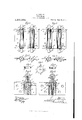
In the accompanying drawings, Figure 1 is a side-elevation of a double acting springhinge with my improved lubricating means applied thereto, and showing the pintle ears made integral with the hinge-leaves, Fig. 2 is a side-elevation of a double acting springhinge with my improved lubricating means applied thereto, and showing the pintle ears made integral with the connecting plate or web, Fig. 3 is a horizontal section on line 8-3 of Fig. 1, Fig. 4 is a horizontal section on line 4.4 of Fig. 2, Fig. 5 is a plan view of my improved bushing, Fig. 6 is a vertical section taken on line 66 of Fig. 5, Fig. 7 is a vertical section taken on line 7-7 of Fig. 5, Fig. 8 is a vertical central section of the adjustable spring-holders and bushings of a double acting spring-hinge shown on a somewhat enlarged scale, and Fig. 9 is a corresponding section of a single-acting hinge.
Similar letters of reference indicate corresponding parts throughout the different figures of the drawings.
Referring to the drawings, and more par ticularly to Fig. l, the barrel a of a double acting spring-hinge,'the connecting web to, and flange-leaves a of the same, the adjustable spring-holders d and the fiXed springholders cl are therein clearly shown. The flange-leaves a are provided with the usual bent-up ears a a which are provided with central perforations for the pintle p.
A washer e is interposed between the ear 0: and the fixed spring-holder d, said washer and ear being provided preferably with a non-circular hole, while the perforation of the ear a adjacent to the adjustable springholder (Z is circular, to conform with the respective ends of the pintle p. The ends of the pintle p are preferably screw-threaded and provided with tips or terminals 29 The washer e is provided with a radial slot or channel 6 which extends from the circumference inwardly toward the center of the washer c, and which serves for distributing the oil injected into the slot e when the fixed spring-holder cl is uppermost and the spring-hinge is to be supplied with lubricating oil, as is shown in the right hand side of Fig. 1. The adjacent face of the fixed spring-holder d is provided with a shallow annular depression or recess d which is concentric with the pintle 70, for receiving the surplus of the lubricating oil which is injected through the slot or channel e after the bearing between the washer e and fixed spring-holder cl is sufiiciently lubricated. The slot or channel 6 of the washer e is of sutficient length so as to extend over the annular depression or recess (Z of the fixed spring-holder d. The oil is then supplied from the depression or recess Z of the fixed springholder to the central pintleopening of the same and lubri cates the contact-surfaces between the pintle p and the fixed spring-holder d, running then along the pintle to the adjustable spring-holder (Z so as to lubricate the contact-surface between the pintle p and the adjustable spring-holder (Z while any remainder of the oil is then conducted into an annular depression or recess CF in the under-side of the adjustable spring-holder al adjacent to the lower car a Between the adjustable spring-holder (Z and the edge of the barrel a, a bushing f having its walls of right-angular cross-section, and having a radial and vertical depressed channel 7, likewise of right-angular cross-section in its rim and side adjacent to the adjustable spring-holder (Z is interposed, the right-angular channel 7 of said bushing 7 being adapted to be non-rotatably seated in a recess f extending along the line of connection of the barrel a with the connecting web w, as shown at F, Figs. 1 and 8, or along the line of connection of the barrel (2; with the barrel-leaves as shown at P, Fig. 2. The rightangular radial and vertical depressed channel f of the bushing f serves for the injection of lubricating oil for lubricating the contact-surfaces between the said bushing f and the adjustable spring-holder (Z and for lubricating the contact-surfaces between the coil-spring s and the interior surface of the barrel.
The construction of the pintle 79 in relation to the ears a and a of the leaf a or connecting web a", and the washer e interposed between the ear a of the leaf a or connecting web in and the fixed springholder (Z is by preference the same as that shown in my pending application, Serial No. 700,167, filed May 28, 1912, and also in co-pending application Serial No. 761,1t3,
filed April 15, 1913, in which the central opening in the ear and in the washer adjacent to the fixed spring-holder is made hexagonal or non-circular and non-rotatably retained on the pintle, which is made of corresponding cross-section at the point of passing through said washer and the adjacent ear of the flange-leaf, thereby connecting the pintle, washer and fiange'leaf into a united movement. By this non-circular connection of the pintle p, flange-leaf a or connecting web 00 and washer e, the slot or channel 6 of the washer is always located at the same designated position in relation to the ear of the flange-leaf a or connecting web w for permitting the convenient oiling of the hinge at all times at the same po sition. 7
As it is sometimes necessary to invert the position of double-acting spring-hinges, so that the adjustable spring-holders are at the upper ends of the barrels and the fixed spring-holders are at the lower ends of the same, or vice versa, and as double-acting spring-hinges are sometimes constructed with one fixed and one adjustable spring holder respectively at the upper ends of the barrels and one adjustable and one fixed spring-holder respectively at the lower ends of the barrels, as shown for example in Letters Patent No. 898,031, granted to me on September 8, 1908, it is necessary to provide means for lubricating the double-acting spring-hinge from either one or the other end, as shown in Fig. 1. This is accomplished, when the adjustable spring-holder (Z is uppermost, by continuing the radial holes (Z in the adjustable spring-holder (Z to the pintle 79, so that the injection of lubricating oil into one of these holes will supply the required quantity of oil for lubricating the contact-surfaces between the adjustable spring-holder 6Z1 and the pintle 79, the oil then running along the pintle and lubricating the contact surface betweenthe pintle 79 and fixed spring-holder (Z at the other end of the hinge, and finally afterentering the annular recess (Z of the fixed spring-holder (Z is spread by the slot or channel 6 of the washer 6 upon the adjacent bearing surface surplus oil will pass into the annular recess (Z of the fixed spring-holder (Z, lubricating the contact-faces between the pintle and the fixed spring-holder (Z, then alongthe pintle to the contact-surfaces between the pintle and the adjustable spring-holder (Z and finally reach the annular recess (Z at the under-side of the adjustable spring-holder (Z As the adjustable spring-holders (Z are connected to and move in unison with their flange-leaves a or connecting web 00 under the recoil of the springs against the tension pins, the joints between the adjustable springholders (Z and the ear of the adjacent flangeleaves a or connecting web 00 need no lubrication.
Disks or washers made of felt or other absorbent material may be inserted into the annular recesses (Z and (Z of the fixed and adjustable spring-holders (Z and (Z respectively for retarding or absorbing the flow of the lubricating oil, and preventing said oil from running out of the hinge and dripping onto the floor, without regard to which end of the hinge is uppermost.
In Fig. 2 is shown a double acting springhinge having the connecting plate or web m made integral with the ears and the hinge leaves made integral with the barrels, both adjustable spring-holders being at the upper ends'of the barrels, and bothfixed springholders being at the lowerends of the barrels, but which is otherwise arranged like the structure described for Fig.1.
I have shown an embodiment of my invention, but it is clear that changes maybe made therein without departing from the spirit of the invention, as defined in the appended claims.
I claim 1. In a spring-hinge, the combination of a barrel, an adjustable Spring-holder, and a bushing at the edge of the barrel adjacent to the adjustable spring-holder, said bushing being provided with a channel for supplying lubricating oil.
2. In a spring-hinge, the combination of a pintle, an adjustable spring-holder having a depression concentric with the pintle, a coil spring, and a non-rotatable bushing adj acent to the spring-holder, said bushing being provided with a radial depression or channel of right-angular cross-section for supplying lubricating oil to the contact surfaces between the bushing and spring-holder, and for lubricating the coil-spring.
3. In a spring-hinge, an improved bush" ing, comprising a vertical member with a channel and having an annular flange with a channel in continuation thereof.
4. In a spring-hinge, the combination of a bushing comprising a vertical member with a channel, and having a flange with a channel, and a barrel having a channel, the bushing being adapted to be non-rotatably seated in the barrel, and the channel of the vertical member of the bushing beingin line with the channel of the barrel.
In testimony that I claim the foregoing as my invention I have signed my name in presence of two subscribing witnesses.
EMIL BOMMER.
Witnesses:
F. Hoes, Jos. BISBANO.
Copies of this patent may be obtained for five cents each, by addressing the Commissioner of Patents,
' Washington, D. 0.
Priority Applications (1)
| Application Number | Priority Date | Filing Date | Title |
|---|---|---|---|
| US82503914A US1131663A (en) | 1914-03-16 | 1914-03-16 | Spring-hinge. |
Applications Claiming Priority (1)
| Application Number | Priority Date | Filing Date | Title |
|---|---|---|---|
| US82503914A US1131663A (en) | 1914-03-16 | 1914-03-16 | Spring-hinge. |
Publications (1)
| Publication Number | Publication Date |
|---|---|
| US1131663A true US1131663A (en) | 1915-03-16 |
Family
ID=3199790
Family Applications (1)
| Application Number | Title | Priority Date | Filing Date |
|---|---|---|---|
| US82503914A Expired - Lifetime US1131663A (en) | 1914-03-16 | 1914-03-16 | Spring-hinge. |
Country Status (1)
| Country | Link |
|---|---|
| US (1) | US1131663A (en) |
-
1914
- 1914-03-16 US US82503914A patent/US1131663A/en not_active Expired - Lifetime
Similar Documents
| Publication | Publication Date | Title |
|---|---|---|
| US5887317A (en) | Adjustable locking hinge | |
| US1131663A (en) | Spring-hinge. | |
| US2126389A (en) | Ball joint | |
| US20230349215A1 (en) | Closure device and self-closing pivot hinge | |
| US1131662A (en) | Spring-hinge. | |
| US1737544A (en) | parsons | |
| US900501A (en) | Screen-door spring-hinge. | |
| US1131664A (en) | Spring-hinge. | |
| US509305A (en) | Door-check | |
| US1131665A (en) | Spring-hinge. | |
| US1152046A (en) | Self-closing hinge. | |
| US833734A (en) | Screen-door hinge. | |
| US538891A (en) | Spring-hinge | |
| US434877A (en) | Charles morrow | |
| US734447A (en) | Spring-hinge. | |
| US822570A (en) | Ball-bearing for spring-hinges. | |
| US774878A (en) | Hinge. | |
| US1131666A (en) | Spring-hinge. | |
| US693734A (en) | Automatic oil-feed cup. | |
| US1144207A (en) | Invisible surface hinge. | |
| US1018391A (en) | Alining plate for floor-hinges. | |
| US920960A (en) | Hinge. | |
| US693927A (en) | Oil-hole cover or cup. | |
| US1956449A (en) | Spindle swing for spinning machines | |
| US1013788A (en) | Door check and closer. |