US11310441B2 - Electronic device for generating a background image for a display apparatus and operation method thereof - Google Patents
Electronic device for generating a background image for a display apparatus and operation method thereof Download PDFInfo
- Publication number
- US11310441B2 US11310441B2 US16/961,595 US201916961595A US11310441B2 US 11310441 B2 US11310441 B2 US 11310441B2 US 201916961595 A US201916961595 A US 201916961595A US 11310441 B2 US11310441 B2 US 11310441B2
- Authority
- US
- United States
- Prior art keywords
- display apparatus
- image
- region
- screen
- markers
- Prior art date
- Legal status (The legal status is an assumption and is not a legal conclusion. Google has not performed a legal analysis and makes no representation as to the accuracy of the status listed.)
- Active
Links
- 238000000034 method Methods 0.000 title claims description 22
- 230000015654 memory Effects 0.000 claims abstract description 57
- 238000004891 communication Methods 0.000 claims abstract description 37
- 230000004044 response Effects 0.000 claims abstract description 24
- 238000011017 operating method Methods 0.000 claims abstract description 11
- 239000003550 marker Substances 0.000 description 50
- 230000002093 peripheral effect Effects 0.000 description 21
- 238000012937 correction Methods 0.000 description 19
- 238000012545 processing Methods 0.000 description 10
- 238000003384 imaging method Methods 0.000 description 9
- 238000010586 diagram Methods 0.000 description 8
- 239000011449 brick Substances 0.000 description 4
- 230000006870 function Effects 0.000 description 4
- 230000008569 process Effects 0.000 description 4
- 230000009977 dual effect Effects 0.000 description 3
- 230000000694 effects Effects 0.000 description 3
- 230000001413 cellular effect Effects 0.000 description 2
- 230000002950 deficient Effects 0.000 description 1
- 230000002708 enhancing effect Effects 0.000 description 1
- 239000011521 glass Substances 0.000 description 1
- 230000003993 interaction Effects 0.000 description 1
- 230000007774 longterm Effects 0.000 description 1
- 238000012986 modification Methods 0.000 description 1
- 230000004048 modification Effects 0.000 description 1
- 230000003287 optical effect Effects 0.000 description 1
- 239000007787 solid Substances 0.000 description 1
- 230000005236 sound signal Effects 0.000 description 1
Images


Classifications
-
- H—ELECTRICITY
- H04—ELECTRIC COMMUNICATION TECHNIQUE
- H04N—PICTORIAL COMMUNICATION, e.g. TELEVISION
- H04N5/00—Details of television systems
- H04N5/222—Studio circuitry; Studio devices; Studio equipment
- H04N5/262—Studio circuits, e.g. for mixing, switching-over, change of character of image, other special effects ; Cameras specially adapted for the electronic generation of special effects
- H04N5/272—Means for inserting a foreground image in a background image, i.e. inlay, outlay
-
- G06K9/00624—
-
- H—ELECTRICITY
- H04—ELECTRIC COMMUNICATION TECHNIQUE
- H04N—PICTORIAL COMMUNICATION, e.g. TELEVISION
- H04N21/00—Selective content distribution, e.g. interactive television or video on demand [VOD]
- H04N21/40—Client devices specifically adapted for the reception of or interaction with content, e.g. set-top-box [STB]; Operations thereof
- H04N21/41—Structure of client; Structure of client peripherals
- H04N21/4104—Peripherals receiving signals from specially adapted client devices
- H04N21/4126—The peripheral being portable, e.g. PDAs or mobile phones
-
- H—ELECTRICITY
- H04—ELECTRIC COMMUNICATION TECHNIQUE
- H04N—PICTORIAL COMMUNICATION, e.g. TELEVISION
- H04N21/00—Selective content distribution, e.g. interactive television or video on demand [VOD]
- H04N21/40—Client devices specifically adapted for the reception of or interaction with content, e.g. set-top-box [STB]; Operations thereof
- H04N21/41—Structure of client; Structure of client peripherals
- H04N21/422—Input-only peripherals, i.e. input devices connected to specially adapted client devices, e.g. global positioning system [GPS]
- H04N21/42204—User interfaces specially adapted for controlling a client device through a remote control device; Remote control devices therefor
- H04N21/42206—User interfaces specially adapted for controlling a client device through a remote control device; Remote control devices therefor characterized by hardware details
- H04N21/4222—Remote control device emulator integrated into a non-television apparatus, e.g. a PDA, media center or smart toy
-
- H—ELECTRICITY
- H04—ELECTRIC COMMUNICATION TECHNIQUE
- H04N—PICTORIAL COMMUNICATION, e.g. TELEVISION
- H04N21/00—Selective content distribution, e.g. interactive television or video on demand [VOD]
- H04N21/40—Client devices specifically adapted for the reception of or interaction with content, e.g. set-top-box [STB]; Operations thereof
- H04N21/41—Structure of client; Structure of client peripherals
- H04N21/422—Input-only peripherals, i.e. input devices connected to specially adapted client devices, e.g. global positioning system [GPS]
- H04N21/4223—Cameras
-
- H—ELECTRICITY
- H04—ELECTRIC COMMUNICATION TECHNIQUE
- H04N—PICTORIAL COMMUNICATION, e.g. TELEVISION
- H04N21/00—Selective content distribution, e.g. interactive television or video on demand [VOD]
- H04N21/40—Client devices specifically adapted for the reception of or interaction with content, e.g. set-top-box [STB]; Operations thereof
- H04N21/43—Processing of content or additional data, e.g. demultiplexing additional data from a digital video stream; Elementary client operations, e.g. monitoring of home network or synchronising decoder's clock; Client middleware
- H04N21/44—Processing of video elementary streams, e.g. splicing a video clip retrieved from local storage with an incoming video stream or rendering scenes according to encoded video stream scene graphs
- H04N21/44008—Processing of video elementary streams, e.g. splicing a video clip retrieved from local storage with an incoming video stream or rendering scenes according to encoded video stream scene graphs involving operations for analysing video streams, e.g. detecting features or characteristics in the video stream
-
- H—ELECTRICITY
- H04—ELECTRIC COMMUNICATION TECHNIQUE
- H04N—PICTORIAL COMMUNICATION, e.g. TELEVISION
- H04N21/00—Selective content distribution, e.g. interactive television or video on demand [VOD]
- H04N21/80—Generation or processing of content or additional data by content creator independently of the distribution process; Content per se
- H04N21/81—Monomedia components thereof
- H04N21/8146—Monomedia components thereof involving graphical data, e.g. 3D object, 2D graphics
- H04N21/8153—Monomedia components thereof involving graphical data, e.g. 3D object, 2D graphics comprising still images, e.g. texture, background image
-
- H—ELECTRICITY
- H04—ELECTRIC COMMUNICATION TECHNIQUE
- H04N—PICTORIAL COMMUNICATION, e.g. TELEVISION
- H04N23/00—Cameras or camera modules comprising electronic image sensors; Control thereof
- H04N23/60—Control of cameras or camera modules
- H04N23/63—Control of cameras or camera modules by using electronic viewfinders
- H04N23/633—Control of cameras or camera modules by using electronic viewfinders for displaying additional information relating to control or operation of the camera
- H04N23/635—Region indicators; Field of view indicators
-
- H—ELECTRICITY
- H04—ELECTRIC COMMUNICATION TECHNIQUE
- H04N—PICTORIAL COMMUNICATION, e.g. TELEVISION
- H04N23/00—Cameras or camera modules comprising electronic image sensors; Control thereof
- H04N23/60—Control of cameras or camera modules
- H04N23/64—Computer-aided capture of images, e.g. transfer from script file into camera, check of taken image quality, advice or proposal for image composition or decision on when to take image
-
- H—ELECTRICITY
- H04—ELECTRIC COMMUNICATION TECHNIQUE
- H04N—PICTORIAL COMMUNICATION, e.g. TELEVISION
- H04N23/00—Cameras or camera modules comprising electronic image sensors; Control thereof
- H04N23/60—Control of cameras or camera modules
- H04N23/66—Remote control of cameras or camera parts, e.g. by remote control devices
- H04N23/661—Transmitting camera control signals through networks, e.g. control via the Internet
-
- H—ELECTRICITY
- H04—ELECTRIC COMMUNICATION TECHNIQUE
- H04N—PICTORIAL COMMUNICATION, e.g. TELEVISION
- H04N23/00—Cameras or camera modules comprising electronic image sensors; Control thereof
- H04N23/80—Camera processing pipelines; Components thereof
-
- H04N5/23229—
-
- H—ELECTRICITY
- H04—ELECTRIC COMMUNICATION TECHNIQUE
- H04N—PICTORIAL COMMUNICATION, e.g. TELEVISION
- H04N5/00—Details of television systems
- H04N5/222—Studio circuitry; Studio devices; Studio equipment
- H04N5/262—Studio circuits, e.g. for mixing, switching-over, change of character of image, other special effects ; Cameras specially adapted for the electronic generation of special effects
- H04N5/2628—Alteration of picture size, shape, position or orientation, e.g. zooming, rotation, rolling, perspective, translation
-
- H—ELECTRICITY
- H04—ELECTRIC COMMUNICATION TECHNIQUE
- H04N—PICTORIAL COMMUNICATION, e.g. TELEVISION
- H04N5/00—Details of television systems
- H04N5/222—Studio circuitry; Studio devices; Studio equipment
- H04N5/262—Studio circuits, e.g. for mixing, switching-over, change of character of image, other special effects ; Cameras specially adapted for the electronic generation of special effects
- H04N5/265—Mixing
-
- H—ELECTRICITY
- H04—ELECTRIC COMMUNICATION TECHNIQUE
- H04N—PICTORIAL COMMUNICATION, e.g. TELEVISION
- H04N5/00—Details of television systems
- H04N5/44—Receiver circuitry for the reception of television signals according to analogue transmission standards
- H04N5/4448—Receiver circuitry for the reception of television signals according to analogue transmission standards for frame-grabbing
-
- H—ELECTRICITY
- H04—ELECTRIC COMMUNICATION TECHNIQUE
- H04N—PICTORIAL COMMUNICATION, e.g. TELEVISION
- H04N21/00—Selective content distribution, e.g. interactive television or video on demand [VOD]
- H04N21/40—Client devices specifically adapted for the reception of or interaction with content, e.g. set-top-box [STB]; Operations thereof
- H04N21/41—Structure of client; Structure of client peripherals
- H04N21/4104—Peripherals receiving signals from specially adapted client devices
- H04N21/4131—Peripherals receiving signals from specially adapted client devices home appliance, e.g. lighting, air conditioning system, metering devices
Definitions
- Various embodiments relate to an electronic device and an operating method thereof, and more particularly, to an electronic device configured to enable a display apparatus to display a wall surface image and an operating method of the electronic device.
- An image display apparatus is an apparatus having a function to display an image to be viewed by a user.
- a user may view broadcasting programs via the image display apparatus.
- the image display apparatus displays, on a display thereof, a broadcasting program from broadcasting signals selected by a user, wherein the broadcasting signals are transmitted from a broadcasting station.
- broadcasting is shifting from analog broadcasting to digital broadcasting.
- Digital broadcasting refers to broadcasting in which digital images and sound signals are transmitted. Digital broadcasting is less vulnerable to external noise than analog broadcasting, and thus has little data loss, is well-suited for error correction, has high resolution, and provides a vivid picture. Also, unlike analog broadcasting, digital broadcasting is capable of two-way services.
- Smart televisions providing content of many sorts in addition to a digital broadcasting function have been provided. Smart televisions do not passively operate according to a selection of a user. Instead, it is aimed at analyzing and providing user needs without a manipulation by the user.
- Various embodiments provide a method and an apparatus for displaying a wall surface image on a screen of a television for enhancing an aesthetic sense of an environment in which the television is mounted.
- the disclosure provides an operating method of an electronic device, the operating method including: generating an event and transmitting the generated event to a display apparatus, the event being configured to instruct a plurality of markers to be displayed on a screen of the display apparatus; determining, from among images obtained from a camera, an image, from which at least a region of a wall surface in the vicinity of the display apparatus is to be extracted, via recognition of the plurality of markers displayed on the screen of the display apparatus in response to the generated event; extracting, from the determined image, a region corresponding to a shape obtained based on the recognized plurality of markers; generating a background image to be displayed on the screen of the display apparatus, by correcting an image of the extracted region; and transmitting the generated background image to the display apparatus so that the generated background image is displayed on the screen of the display apparatus.
- wall surface images may be effectively captured and processed to generate a background image to be displayed on the display apparatus, and thus, an aesthetic sense of an environment, in which the display apparatus is mounted, may be enhanced.
- FIG. 1 is a reference view for describing a concept of displaying a wall surface image on a display apparatus according to embodiments.
- FIG. 2 is a reference view for describing a method of displaying a wall surface image on a display apparatus, according to an embodiment.
- FIG. 3 is a schematic view for describing examples of a system configured to display a wall surface image on a display apparatus, according to embodiments.
- FIG. 4 is a block diagram of a mobile device 100 , a display apparatus 200 , and a server 300 , according to an embodiment.
- FIG. 5 shows an operating method of a mobile device, according to an embodiment.
- FIG. 6 is a flowchart of operations of a mobile device, a server, and a display apparatus for displaying a background image on the display apparatus by using an image of a wall surface on which the display apparatus is mounted, according to an embodiment.
- FIG. 7 is a flowchart of operations of a mobile device, a server, and a display apparatus for displaying a background image on the display apparatus by using an image of a wall surface on which the display apparatus is mounted, according to an embodiment.
- FIG. 8 shows a user interface provided by a mobile device 100 by executing a device control application, according to an embodiment.
- FIG. 9 shows an example of a preview image displayed on a display of a mobile device 100 , according to an embodiment.
- FIG. 10 shows a region to be captured of a wall surface in the vicinity of a display apparatus, according to an embodiment.
- FIG. 11 is a reference view for describing a size of a region to be captured of a wall surface in the vicinity of a display apparatus, according to an embodiment.
- FIG. 12 is a reference view for describing a method, performed by a mobile device, of transmitting a marker display event to a display apparatus, according to an embodiment.
- FIG. 13 is a view for describing a method of determining a location to display a marker according to a region selected to be captured, according to an embodiment.
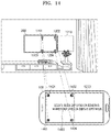
- FIG. 14 is a reference view for describing an example of displaying one or more guides in a mobile device, according to an embodiment.
- FIG. 15 is a reference view for describing an example of displaying one or more guides in a mobile device, according to an embodiment.
- FIG. 16 is a reference view for describing an example of capturing a region which is apart from a display apparatus by a thickness of a bezel, according to an embodiment.
- FIG. 17 is a reference view for describing an example in which it is required to correct an image of an extracted region.
- FIG. 18 is a reference view for describing correction of a region when a captured image is biased in a negative direction of an X axis, according to an embodiment.
- FIG. 19 is a reference view for describing correction of a region when a captured image is biased in a positive direction of an X axis, according to an embodiment.
- FIG. 20 is a reference view for describing correction of a region when a captured image is biased in a positive direction of a Y axis, according to an embodiment.
- FIG. 21 is a reference view for describing correction of an area when a captured image is biased in a negative direction of a Y axis, according to an embodiment.
- FIG. 22 is a reference view for describing correction of an area when a captured image is biased in a positive direction of a Z axis, according to an embodiment.
- FIG. 23 is a reference view for describing an application example of a curved display apparatus, according to an embodiment.
- an electronic device includes: a camera; a display; a communication interface; a memory storing one or more instructions; and a processor configured to execute the one or more instructions stored in the memory to: generate an event and transmit, to a display apparatus, the generated event to instruct a plurality of markers to be displayed on a screen of the display apparatus; determine, from among images obtained from the camera, an image, from which at least a region of a wall surface in the vicinity of the display apparatus is to be extracted, based on recognition of the plurality of markers displayed on the screen of the display apparatus in response to the generated event; extract, from the determined image, a region corresponding to a shape obtained based on the recognized plurality of markers; generate a background image to be displayed on the screen of the display apparatus, by correcting an image of the extracted region; and transmit the generated background image to the display apparatus so that the generated background image is displayed on the screen of the display apparatus.
- the processor may further be configured to execute the one or more instructions to: obtain size information of the screen of the display apparatus; and determine, based on the obtained size information, a location of the screen of the display apparatus on which the plurality of markers are to be displayed, and generate the event including information about the determined location.
- the processor may further be configured to execute the one or more instructions to, when the plurality of markers displayed on the screen of the display apparatus are recognized, determine, from the images obtained from the camera, an image in which the plurality of markers exist, as an image, from which the background image is to be extracted.
- the at least the region of the wall surface on which the display apparatus is mounted may include at least one of a left region, a right region, an upper region, and a lower region of the wall surface in the vicinity of the display apparatus.
- the processor may further be configured to execute the one or more instructions to correct the image of the extracted region by performing at least one of adjusting of a length of at least one side of the image, rotating the image of the extracted region, and symmetrizing the image of the extracted region.
- the processor may further be configured to execute the one or more instructions to generate the background image by combining an image generated by correcting the image of the extracted region with a symmetric image of the corrected image.
- the processor may further be configured to execute the one or more instructions to: when the determined image is an image obtained from a left region or a right region of the wall surface in the vicinity of the display apparatus, obtain the symmetric image by symmetrizing the obtained image in a left direction or a right direction; and when the determined image is an image obtained from an upper region or a lower region of the wall surface in the vicinity of the display apparatus, obtain the symmetric image by symmetrizing the obtained image in an upper direction or a lower direction.
- the processor may further be configured to execute the one or more instructions to transmit the event and the background image to the display apparatus via a server.
- the shape obtained based on the recognized plurality of markers may include a polygonal shape obtained by connecting the recognized plurality of markers.
- an operating method of an electronic device includes: generating an event to instruct a plurality of markers to be displayed on a screen of a display apparatus and transmitting the generated event to the display apparatus; determining, from among images obtained from a camera, an image, from which at least a region of a wall surface in the vicinity of the display apparatus is to be extracted, via recognition of the plurality of markers displayed on the screen of the display apparatus in response to the generated event; extracting, from the determined image, a region corresponding to a shape obtained based on the recognized plurality of markers; generating a background image to be displayed on the screen of the display apparatus, by correcting an image of the extracted region; and transmitting the generated background image to the display apparatus so that the generated background image is displayed on the screen of the display apparatus.
- a computer-readable recording medium has recorded thereon a program for executing an operating method of a display apparatus on a computer.
- FIG. 1 is a reference view for describing a concept of displaying a wall surface image on a display apparatus according to embodiments.
- a display apparatus 200 is mounted on a wall surface 10 .
- the display apparatus 200 may display an image 11 of a region of the wall surface 10 , in a state other than a normal operation mode of the display apparatus 200 , in which content is displayed based on a user input.
- the display apparatus 200 may display the image 11 of a region of the wall surface 10 , and thus, an aesthetic sense of an environment in which the display apparatus 200 is mounted may be enhanced.
- a user may be provided with an experience as if the display apparatus 200 does not exist on the wall surface 10 , while the display apparatus 200 is not operating.
- a television (TV) providing this effect may be referred to as a glass TV.
- the user may have a more authentic experience in which the display apparatus 200 is felt like a wall surface, as the actual wall surface 10 and the image 11 of the wall surface that the display apparatus 200 displays are more smoothly connected.
- the display apparatus 200 After the display apparatus 200 is mounted on the wall surface 10 , it is difficult to identify a region of the wall surface 10 , which is covered by the display apparatus 200 .
- FIG. 2 is a reference view for describing a method of displaying a wall surface image on a display apparatus, according to an embodiment.
- the display apparatus 200 mounted on the wall surface 10 may display one or more markers 21 .
- a mobile device 100 may display one or more guides on a display of the mobile device 100 .
- the mobile device 100 may capture an image of the wall surface 10 by using the one or more guides 23 , and the one or more markers 21 displayed on the display apparatus 200 .
- the mobile device 100 may capture the image of the wall surface.
- an image of a region 22 peripheral to the display apparatus 200 on the right side may be recognized at a right portion 24 of a region captured by the mobile device 100 , and thus, the mobile device 100 may capture the region 22 of the wall surface 10 .
- the region 22 is a region peripheral to the display apparatus 200 on the right side, and thus, the mobile device 100 may perform an appropriate processing operation by using a captured image of the region 22 , to generate a wall surface image to be displayed on the display apparatus 200 , that is, a background image. Also, the region 22 is a region directly adjacent to the display apparatus 200 , and thus, when the image of the region 22 is used to generate the background image to be displayed on the display apparatus 200 , it may be possible to generate an image smoothly harmonized with a peripheral region of the display apparatus 200 .
- Regions to be captured may include any one of a left region, an upper region, and a lower region of the display apparatus 200 .
- the mobile device 100 may extract a region from the captured image and correct the region, by using a polygonal shape obtained by a marker detected from the display apparatus 200 .
- FIG. 3 is a schematic view for describing examples of a system configured to display a wall surface image on a display apparatus, according to embodiments.
- the system may include the mobile device 100 , the display apparatus 200 , and a server 300 .
- the mobile device 100 , the display apparatus 200 , and the server 300 may communicate with one another via a communication network 30 .
- the communication network 30 may include broadband networks according to various communication standards, such as Zigbee, 3rd generation (3G), 3rd generation partnership project (3GPP), long term evolution (LTE), etc.
- the mobile device 100 may receive information about the display apparatus 200 , in detail, information about a screen size, from the display apparatus 200 via the server 300 , or from the server 300 , and may generate a marker display event based on the received information.
- the marker display event may be transmitted to the display apparatus 200 via the server 300 , and when the display apparatus 200 receives the marker display event, the display apparatus 200 may display one or more markers on a screen in response to the marker display event.
- the markers may be displayed on various locations of the screen of the display apparatus 200 .
- the mobile device 100 may obtain an image of a wall surface in the vicinity of the display apparatus 200 , by using the markers displayed on the display apparatus 200 .
- the mobile device 100 may obtain an image of a peripheral region of the display apparatus 200 according to a location of the markers displayed on the screen of the display apparatus 200 . For example, when the markers are displayed on a left half screen of the display apparatus 200 , the mobile device 100 may obtain an image of a left peripheral region of the display apparatus 200 .
- the mobile device 100 may generate a background image to be displayed on the display apparatus 200 by using the obtained original image and a symmetric image obtained by symmetrizing the original image, and may transmit the generated background image to the display apparatus 200 via the server 300 .
- the display apparatus 200 may display the background image on the screen.
- the system may include the mobile device 100 and the display apparatus 200 .
- the mobile device 100 and the display apparatus 200 may perform communication with each other via short-range wireless communication, etc.
- the short-range wireless communication may include short-range wireless communication protocols, such as Bluetooth, Bluetooth low energy (BLE), Wifi, Wifi-direct, near-field communication (NFC), infrared communication, laser beam communication, etc.
- the mobile device 100 may directly receive screen information of the display apparatus 200 from the display apparatus 200 and may directly transmit a marker display event generated based on the received screen information to the display apparatus 200 .
- the display apparatus 200 may display one or more markers on the screen in response to the marker display event.
- the mobile device 100 may obtain an image of a peripheral wall surface of the display apparatus 200 by using the markers displayed on a screen of the display apparatus 200 , generate a background image by using the obtained image, and transmit the generated background image to the display apparatus 200 .
- the display apparatus 200 may receive the background image and display the received background image on the screen.
- FIG. 4 is a block diagram of the mobile device 100 , the display apparatus 200 , and the server 300 , according to an embodiment.
- the display apparatus 200 may process content data received from various sources and display an image.
- the display apparatus 200 may receive a radio-frequency (RF) signal from a broadcasting station by using an RF antenna.
- the display apparatus 200 may receive content provided by a content provision server through a communication network based on an Internet protocol.
- the display apparatus 200 may receive content from an external device connected to the display apparatus 200 via various ports or an HDMI.
- the external device may include, for example, a set top box, a game device, a BD player, a PC, a USB, etc.
- the display apparatus 200 may receive content from a mobile device connected with the display apparatus 200 for communication or may obtain content data from a memory stored in the display apparatus 200 or connected for a local access.
- the display apparatus 200 may include a display 210 , a communication interface 220 , a sensor 230 , and a controller 240 .
- the display 210 may display, on a screen, content received from various sources, under control of the controller 240 .
- Various sources may include, for example, a communication interface 220 , a memory 250 , and an inputter/outputter.
- the display 210 may include a PDP, an LCD, an OLED, a flexible display, etc.
- the display 210 may include a three-dimensional (3D) display.
- the display 210 may include a touch screen, which may be used as an input device as well as an output device.
- the communication interface 220 may connect the display apparatus 200 with an external device, for example, the mobile device 100 or the server 300 , under control of the controller 240 .
- the communication interface 220 may include one or a combination of a wireless LAN, Bluetooth, and wired Ethernet in correspondence to the performance and the structure of a display apparatus.
- the communication interface 220 may further include other short-range communication interfaces, in addition to Bluetooth.
- the communication interface 220 may further include NFC and BLE.
- the sensor 230 may sense a voice of a user, an image of a user, or an interaction of a user and may include a microphone configured to receive an uttered voice of a user, a camera portion configured to receive an image corresponding to a motion of a user within a recognition range of a camera, the motion including a gesture, and a light receiver configured to receive a light signal (including a control signal) received from an external remote control device according to a user input.
- the sensor 230 may sense a command or a control signal from the remote control device via the light receiver and may transmit the sensed command or control signal to the controller 240 .
- the remote control device may be realized as various types of devices for controlling the display apparatus 200 .
- the remote control device may be realized as a remote controller or a cellular phone.
- the memory 250 may store various data, programs, or applications for operating and controlling the display apparatus 200 under control of the controller 240 .
- the memory 250 may store an operating system for controlling the display apparatus 200 and a controller, an application initially provided from a manufacturer or downloaded from the outside, a graphical user interface (GUI) related to the application, an object (for example, an image, text, an icon, a button, etc.) for providing the GUI, user information, documents, databases, or related data.
- GUI graphical user interface
- the memory 250 may include ROM, RAM, or a memory card (for example, a micro SD card or a USB memory not shown) mounted in the display apparatus 200 .
- the memory 200 may include a nonvolatile memory, a volatile memory, a hard disk drive (HDD), or a solid state drive (SSD).
- the memory 250 may include one or more instructions for transmitting information about the display apparatus 200 in response to a request of the mobile device 100 or the server 300 .
- the information about the display apparatus 200 may include size information of the display apparatus 200 , in detail, screen size information of the display apparatus 200 .
- the memory 250 may include one or more instructions for receiving a marker display event from the mobile device 100 or the server 300 and displaying one or more markers on the display in response to the marker display event.
- the memory 250 may include one or more instructions for receiving a background image from the mobile device 100 or the server 300 and displaying the background image on the display.
- the background image may include an image generated by using a peripheral region of a wall surface on which the display apparatus 200 is mounted.
- the controller 240 may control general operations of the display apparatus 200 and signal flows among the components of the display apparatus 200 and may process data. When there is a user input or a pre-set and stored condition is satisfied, the controller 240 may execute an operation system (OS) and various applications stored in the memory 250 .
- OS operation system
- Processors used as the controller 240 may include a graphic processing unit (not shown) for processing graphics corresponding to a video.
- the processors may be realized as a system on chip (SoC) in which a core (not shown) and a GPU (not shown) are integrated.
- SoC system on chip
- the processors may include a single core, a dual core, a triple core, a quad core, and a multi-core.
- the processors may include a plurality of processors.
- the processors may be realized as a main processor (not shown) and a sub-processor (not shown) operating in a sleep mode.
- the controller 240 may execute the one or more instructions stored in the memory 250 to transmit the information about the display apparatus 200 in response to a request from the mobile device 100 or the server 300 .
- the controller 240 may execute the one or more instructions stored in the memory 250 to receive a marker display event from the mobile device 100 or the server 300 and to display one or more markers on the display in response to the marker display event.
- the controller 240 may execute the one or more instructions stored in the memory 250 to receive a background image from the mobile device 100 or the server 300 and display the background image on the display.
- the display apparatus 200 may further include an inputter/outputter configured to receive a video (for example, an image, etc.) an audio (for example, a voice, music, etc.), and additional information (for example, EPG, etc.) from the outside of the display apparatus 200 under control of the controller 240 .
- the inputter/outputter may include one or a combination of a high-definition multimedia interface (HDMI) port, a component jack, a PC port, and a USB port.
- HDMI high-definition multimedia interface
- the display apparatus 200 may include a TV, which, however, is an embodiment.
- the display apparatus 200 may be realized as an electronic device including a display.
- the display apparatus 200 may be realized as various electronic devices, such as a desk top computer, a digital broadcasting terminal, etc.
- the display apparatus 200 may be realized not only as a flat display apparatus, but also as a curved display apparatus having a screen having a curvature or a flexible display apparatus, of which a curvature
- the display apparatus 200 may be electrically connected to an additional external device (for example, a set top box not shown) having a tuner portion.
- the display apparatus 200 may be realized as an analog TV, a digital TV, a 3D-TV, a smart TV, an LED TV, an OLED TV, a plasma TV, a monitor, etc.
- the display apparatus 200 is not limited thereto.
- the illustrated block diagram of the display apparatus 200 is a block diagram according to an embodiment.
- the components of the block diagram may be integrated, added, or omitted according to specifications of the actual display apparatus 200 .
- two or more components may be integrated into one component or one component may be divided into two components, according to necessity.
- a function performed by each of blocks is explained to describe embodiments, and the specific operations or devices do not limit the scope of claims of the disclosure.
- the server 300 may be a computing device configured to execute a server program for providing services in response to a request of a user (a client).
- the server 300 may include a communication interface 310 and a controller 320 .
- the communication interface 310 may connect the server 300 with an external device, for example, the mobile device 100 or the display apparatus 200 , under control of the controller 320 .
- the communication interface 220 may include one or a combination of a wireless LAN, Bluetooth, and wired Ethernet in correspondence to the performance and the structure of the display apparatus.
- the memory 330 may store various data, programs, or applications for operating and controlling the server 300 under control of the controller 320 .
- the memory 330 may store an operating system for controlling the server 300 and a controller, an application initially provided from a manufacturer or downloaded from the outside, a graphical user interface (GUI) related to the application, an object (for example, an image, text, an icon, a button, etc.) for providing the GUI, user information, documents, databases, or related data.
- GUI graphical user interface
- the memory 330 may include ROM, RAM, or a memory card (for example, a micro SD card or a USB memory not shown) mounted in the server 300 . Also, the memory 330 may include a nonvolatile memory, a volatile memory, an HDD, or an SSD.
- the memory 330 may include one or more instructions for transmitting an application for controlling one or more assumed devices to the mobile device 100 , in response to a request from the mobile device 100 .
- the device control application may be used to control the display apparatus 200 , and in particular, the device control application may include one or more instructions for setting a background image of the display apparatus 200 .
- the memory 330 may include one or more instructions for transmitting information about the display apparatus 200 in response to a request of the mobile device 100 .
- the information about the display apparatus 200 may include size information of the display apparatus 200 , in detail, screen size information of the display apparatus 200 .
- the memory 330 may include one or more instructions for receiving a marker display event from the mobile device 100 and transmitting the marker display event to the display apparatus 200 .
- the memory 330 may include one or more instructions for receiving a background image from the mobile device 100 and transmitting the background image to the display apparatus 200 .
- the background image may include an image generated by using a peripheral region of a wall surface on which the display apparatus 200 is mounted.
- the controller 320 may control general operations of the server 300 and signal flows among the components of the server 300 and may process data. When there is a user input or a pre-set and stored condition is satisfied, the controller 320 may execute an OS and various applications stored in the memory 250 .
- Processors used as the controller 320 may include a graphic processing unit (not shown) for processing graphics corresponding to a video.
- the processors may be realized as an SoC, in which a core (not shown) and a GPU (not shown) are integrated.
- the processors may include a single core, a dual core, a triple core, a quad core, and a multi-core.
- the processors may include a plurality of processors.
- the processors may be realized as a main processor (not shown) and a sub-processor (not shown) operating in a sleep mode.
- the controller 320 may execute the one or more instructions stored in the memory 330 to transmit an application for controlling one or more home appliances to the mobile device 100 in response to a request from the mobile device 100 .
- the device control application may be used to control the display apparatus 200 , and in particular, the device control application may include one or more instructions for setting a background image of the display apparatus 200 .
- the controller 320 may execute the one or more instructions stored in the memory 330 to transmit the information about the display apparatus 200 in response to a request from the mobile device 100 .
- the information about the display apparatus 200 may include size information of the display apparatus 200 , in detail, screen size information of the display apparatus 200 .
- the controller 320 may execute the one or more instructions stored in the memory 330 to receive a marker display event from the mobile device 100 and to transmit the marker display event to the display apparatus 200 .
- the controller 320 may execute the one or more instructions stored in the memory 330 to receive a background image from the mobile device 100 and to transmit the background image to the display apparatus 200 .
- the background image may include an image generated by using a peripheral region of a wall surface on which the display apparatus 200 is mounted.
- the mobile device 100 may capture an image of a wall surface on which the display apparatus 200 is mounted, generate a background image to be displayed on a screen of the display apparatus 200 based on the captured image, and transmit the generated image to the display apparatus 200 via the server 300 .
- the mobile device 100 may include an imaging sensor circuit 110 , a communication interface 120 , a display 130 , a memory 140 , and a controller 150 .
- the imaging sensor circuit 110 may receive an image (for example, a consecutive frame) corresponding to a motion of a user within a recognition range of an imaging sensor, the motion including a gesture.
- the imaging sensor circuit 110 may be realized as a camera.
- the imaging sensor circuit 110 according to an embodiment may capture an image indicating a wall surface to be displayed by the display apparatus 200 .
- the communication interface 120 may connect the mobile device 100 with an external device, for example, the display apparatus 200 or the server 300 , under control of the controller 150 .
- the communication interface 120 may include one or a combination of a wireless LAN, Bluetooth, and wired Ethernet in correspondence to the performance and the structure of a mobile device.
- the communication interface 120 may include, in detail, a mobile communicator and a sub-communicator.
- the mobile communicator may perform broadband networks according to various communication standards, such as Zigbee, 3G, 3GPP, LTE, etc.
- the mobile communicator may be used for communication with the server 300 .
- the sub-communicator may perform communication with peripheral devices by using short-range wireless communication protocols, such as Bluetooth, BLE, Wifi, NFC, infrared communication, laser beam communication, etc.
- the sub-communicator may be used for communication with the display apparatus 200 .
- the display 130 may display content received from various sources on a screen under control of the controller 150 .
- Various sources may include, for example, a communication interface 120 , a memory 140 , and an inputter/outputter.
- the display 130 may include a touch screen, which may be used as an input device as well as an output device.
- the memory 140 may store various data, programs, or applications for operating and controlling the mobile device 100 under control of the controller 150 .
- the memory 140 may store an operating system for controlling the mobile device 100 and a controller, an application initially provided from a manufacturer or downloaded from the outside, a GUI related to the application, an object (for example, an image, text, an icon, a button, etc.) for providing the GUI, user information, documents, databases, or related data.
- the memory 140 may include ROM, RAM, or a memory card (for example, a micro SD card or a USB memory not shown) mounted in the mobile device 100 .
- the memory 140 may include one or more instructions for transmitting a request for downloading an application for controlling home appliances to the server 300 and receiving and storing a device control application in response to the request.
- the device control application may include one or more instructions for controlling the display apparatus 200 , and in particular, the one or more instructions used to set a background image of the display apparatus 200 .
- the memory 140 may include one or more instructions for transmitting information about the display apparatus 200 to the mobile device 100 or the server 300 .
- the information about the display apparatus 200 may include size information of the display apparatus 200 , in detail, screen size information of the display apparatus 200 .
- the memory 140 may include one or more instructions for generating a marker display event by using the information about the display apparatus 200 and transmitting the marker display event to the mobile device 100 or the server 300 .
- the marker display event may include information about a location of one or more markers to be displayed on a screen of the display apparatus according to a screen size of the display apparatus 200 .
- the memory 140 may include one or more instructions for obtaining an image of a region of a wall surface on which the display apparatus 200 is mounted by using the one or more markers displayed on the screen of the display apparatus 200 in response to the marker display event, processing the obtained image to generate a background image to be displayed on the screen of the display apparatus 200 , and transmitting the background image to the display apparatus 200 or the server 300 .
- the memory 140 may include one or more instructions for generating an event instructing a plurality of markers to be displayed on the screen of the display apparatus and transmitting the event to the display apparatus, determining, from among images obtained by a camera, an image from which at least a region of a wall surface in the vicinity of the display apparatus is to be extracted, based on recognizing the plurality of markers displayed on the screen of the display apparatus in response to the generated event, extracting, from the determined image, a region corresponding to a shape obtained based on the recognized plurality of markers, generating a background image to be displayed on the screen of the display apparatus by correcting an image of the extracted region, and transmitting the generated background image to the display apparatus for the display apparatus to display the generated background image on the screen.
- the correction of the image of the extracted region may be performed by adjusting a length of one or more sides of the image of the extracted region, rotating the image of the extracted region, obtaining a symmetric region of the extracted region, etc.
- the controller 150 may control general operations of the mobile device 100 and signal flows among the components of the mobile device 100 and may process data. When there is a user input or a pre-set and stored condition is satisfied, the controller 150 may execute an OS and various applications stored in the memory 140 .
- Processors used as the controller 150 may include a graphic processing unit (not shown) for processing graphics corresponding to a video.
- the processors may be realized as an SoC, in which a core (not shown) and a GPU (not shown) are integrated.
- the processors may include a single core, a dual core, a triple core, a quad core, and a multi-core.
- the processors may include a plurality of processors.
- the processors may be realized as a main processor (not shown) and a sub-processor (not shown) operating in a sleep mode.
- the controller 150 may execute the one or more instructions stored in the memory 140 to transmit a request for downloading an application for controlling home appliances to the server 300 and receive and store a device control application according to the request.
- the device control application may include one or more instructions for controlling the display apparatus 200 , and in particular, the one or more instructions used to set a background image of the display apparatus 200 .
- the controller 150 may execute the one or more instructions stored in the memory 140 to transmit the information about the display apparatus 200 to the mobile device 100 or the server 300 .
- the information about the display apparatus 200 may include size information of the display apparatus 200 , in detail, screen size information of the display apparatus 200 .
- the controller 150 may execute the one or more instructions stored in the memory 140 to generate a marker display event by using the information about the display apparatus 200 and to transmit the marker display event to the mobile device 100 or the server 300 .
- the marker display event may include information about a location of one or more markers to be displayed on a screen of the display apparatus according to a screen size of the display apparatus 200 .
- the controller 150 may execute the one or more instructions stored in the memory 140 to obtain an image of a region of the wall surface on which the display apparatus 200 is mounted by using the one or more markers displayed on the screen of the display apparatus 200 in response to the marker display event, to generate the background image to be displayed on the screen of the display apparatus 200 by processing the obtained image, and to transmit the background image to the display apparatus 200 or the server 300 .
- the controller 150 may execute the one or more instructions stored in the memory 140 to extract, from an obtained image, a region of a shape corresponding to a polygon obtained by connecting the one or more markers displayed on the screen of the display apparatus 200 , to correct an image of the obtained region, and to generate the background image to be displayed on the screen of the display apparatus by using the corrected image.
- the correction of the image of the extracted region may be performed by adjusting a length of one or more sides of the image of the extracted region, rotating the image of the extracted region, obtaining a symmetric region of the extracted region, etc.
- the illustrated block diagram of the mobile device 100 is a block diagram according to an embodiment.
- the components of the block diagram may be integrated, added, or omitted according to specifications of the actual mobile device 100 . That is, two or more components may be integrated into one component or one component may be divided into two components, according to necessity. Also, a function performed by each of blocks is explained to describe embodiments, and the specific operations or devices do not limit the scope of claims of the disclosure.
- the mobile device 100 may be realized as various electronic devices, such as a cellular phone, a tablet PC, a digital camera, a camcorder, a laptop computer, a tablet PC, an electronic book terminal, a digital broadcasting terminal, a personal digital assistant (PDA), a portable multimedia player (PMP), a navigation device, an MP3 player, a wearable device, etc.
- PDA personal digital assistant
- PMP portable multimedia player
- FIG. 5 shows an operating method of a mobile device, according to an embodiment.
- the mobile device 100 may generate an event instructing one or more markers to be displayed on a screen of the display apparatus 200 and may transmit the generated event to the display device 200 .
- the mobile device 100 may determine a location of the one or more markers to be displayed on the screen of the display apparatus 200 with reference to screen size information of the display apparatus 200 .
- the mobile device 100 may receive the screen size information of the display apparatus 200 from a user, from the display apparatus 200 , or from the server 300 .
- the mobile device 100 may generate a marker display event including the determined location of the one or more markers and transmit the generated marker display event to the display apparatus 200 .
- the mobile device 100 may directly transmit the marker display event to the display apparatus 200 or may transmit the marker display event to the display apparatus 200 via the server 300 .
- the mobile device 100 may determine, from among images obtained by using a camera, an image from which at least a region of a wall surface in the vicinity of the display apparatus 200 is to be extracted, based on recognizing the one or more markers displayed on the screen of the display apparatus in response to the generated marker display event.
- the mobile device 100 may determine, from among the images obtained from the camera, an image from which at least a region of a wall surface in the vicinity of the display apparatus 200 is to be extracted, by using the one or more markers displayed on the screen of the display apparatus and one or more guides displayed on a display of the mobile device.
- the mobile device 100 may extract, from the determined image, a region corresponding to a shape obtained based on the one or more markers displayed on the screen of the display apparatus 200 .
- the mobile device 100 may correct an image of the extracted region and generate a background image to be displayed on the screen of the display apparatus.
- the mobile device 100 may correct the image of the extracted region and use the corrected image and a symmetric image of the corrected image to generate the background image.
- the correction of the image of the extracted region may be performed by at least one of adjusting a length of one or more sides (edges) of the image of the extracted region, rotating the image of the extracted region, obtaining a symmetric region of the extracted region, etc.
- the mobile device 100 may transmit the generated background image to the display apparatus, so that the generated background image is displayed on the screen of the display apparatus.
- the mobile device 100 may directly transmit the generated background image to the display apparatus 200 or may transmit the generated background image to the display apparatus 200 via the server 300 .
- FIGS. 6 and 7 are flowcharts of operations of a mobile device, a server, and a display apparatus for displaying a background image on the display apparatus by using an image of a wall surface on which the display apparatus is mounted, according to an embodiment.
- the mobile device 100 may download and install a device control application, and in operation S 710 , the server 300 may transmit the device control application to the mobile device 100 .
- the server may transmit the device control application to the mobile device 100 and the mobile device 100 may receive and install the device control application.
- the device control application may include applications for controlling various home appliance devices, such as a refrigerator, a display apparatus, a laundry machine, an audio device, etc.
- the mobile device 100 may execute the installed device control application.
- the mobile device 100 may receive a user input for selecting a background screen setting menu.
- FIG. 8 shows a user interface provided by the mobile device 100 by executing a device control application, according to an embodiment.
- a first user interface 810 of the device control application executed by the mobile device 100 may receive a user input for selecting a device to control.
- the first user interface 810 may display, as a device to control, a display apparatus 811 , an audio device 812 , a laundry machine 813 , and a refrigerator 814 , and a user may select one of the displayed devices.
- the mobile device 100 may output a second user interface 820 .
- the second user interface 820 may display menu items related to controlling of the display apparatus, and one of the menu items may be a background screen setting item 821 .
- the background screen setting item 821 may be a menu item, through which it may be set for the display apparatus to display the same image as an image of a wall surface on which the display apparatus is mounted, while the display apparatus does not operate based on user manipulation.
- the mobile device 100 may output a third user interface 830 .
- the third user interface 830 may include an input window 831 through which a model name of the display apparatus may be input.
- the mobile device 100 may receive the model name of the display apparatus through the input window 831 .
- the mobile device 100 may request and obtain screen information of the display apparatus.
- the screen information of the display apparatus may include a size of the screen of the display apparatus 200 .
- the screen information of the display apparatus may be used to determine a location of one or more markers to be displayed on the screen of the display apparatus.
- the screen information of the display apparatus may be included in product information of the display apparatus and may be obtained by using the model name of the display apparatus.
- the mobile device 100 may obtain the screen information of the display apparatus by using the model name of the display apparatus received through the third user interface 830 .
- the mobile device 100 may transmit the model name of the display apparatus to the server 300 and may receive the screen information of the display apparatus, the screen information corresponding to the model name of the display apparatus, from the server 300 .
- the server 300 may transmit the model name of the display apparatus received from the mobile device 100 to the display apparatus 200 , and the display apparatus 200 may transmit the screen information of the display apparatus, the screen information corresponding to the model name of the display apparatus, to the mobile device 100 via the server 300 .
- the mobile device 100 may store the screen information of the display apparatus, the screen information corresponding to the model name of the display apparatus, and thus, may obtain the screen information of the display apparatus without a request from the server 300 .
- the mobile device 100 may select a region of an image of a wall surface on which the display apparatus 200 is mounted.
- the mobile device 100 may be converted into a photo capturing mode after obtaining the screen information of the display apparatus.
- a camera of the mobile device 100 may sense the image of the wall surface including the display apparatus 200 and on which the display apparatus 200 is mounted and a display of the mobile device 100 may display the image of the wall surface including the display apparatus 200 as a preview image.
- the mobile device 100 may display a guideline of a region to be captured, on the preview image.
- the mobile device 100 may display guidelines of a plurality of regions to be captured and may receive an input of selecting one region from the user. Methods of selecting a region to be captured via the mobile device 100 will be described with reference to FIGS. 9 through 11 .
- FIG. 9 shows an example of a preview image displayed on a display of the mobile device 100 , according to an embodiment.
- the mobile device 100 may obtain an image of a wall surface on which the display apparatus 200 is mounted by using a camera and display the obtained image on the display as a preview image 900 .
- the display 100 may display a guideline for selecting a region to be captured, on the displayed preview image 900 .
- a guideline 910 indicating a right region A of the display apparatus 200 a guideline 920 indicating an upper region B of the display apparatus 200 , and a guideline 930 indicating a left region C of the display apparatus 200 are displayed on the preview image 900 .
- a user may select one of the guidelines 910 , 920 , and 930 to select an image region of the wall surface, the image region being to be captured.
- the mobile device 100 may variously determine a region to be captured of the wall surface.
- the mobile device 100 may determine a region to be captured of the wall surface, as default.
- the mobile device 100 may display regions of the wall surface that are to be captured, as illustrated in FIG. 9 , so that a user may select a region.
- the mobile device 100 may determine a location of a marker to be displayed on a display apparatus according to the selection of the region to be captured of the wall surface, and may determine an event including information about the location of the marker to the display apparatus.
- FIG. 10 shows a region to be captured of a wall surface in the vicinity of a display apparatus, according to an embodiment.
- FIG. 10 illustrates an example in which, in the case of a stand-type display apparatus 200 , wall surface images of a right region, an upper region, and a left region of a wall surface in the vicinity of the display apparatus 200 are captured, according to an embodiment.
- a screen size of the display apparatus 200 is (width X, height Y)
- a size of the left region or the right region to be captured may be determined as (width X/2, height Y)
- a size of the upper region to be captured may be determined as (width X, height Y/2).
- Each of regions A, B, and C corresponds to a half of the screen size of the display apparatus 200 .
- a background image to be displayed on a screen of the display apparatus 200 may be generated by doubling the size of the region that is captured.
- FIG. 10 illustrates an example in which, in the case of a wall-hanging-type display apparatus 200 , wall surface images of a left region, a right region, an upper region, and a lower region of a wall surface in the vicinity of the display apparatus 200 are captured, according to an embodiment.
- FIG. 11 is a reference view for describing a size of a region to be captured of a wall surface in the vicinity of a display apparatus, according to an embodiment.
- FIG. 11 illustrates an example in which wall surface images of a left region, a right region, an upper region, and a lower region of a wall surface in the vicinity of the display apparatus 200 are captured, according to an embodiment.
- a screen size of the display apparatus 200 is (width X, height Y)
- a size of the left region or the right region to be captured may be determined as (width X/3, height Y)
- a size of the upper region or the lower region to be captured may be determined as (width X, height Y/3).
- Each of regions A, B, C and D corresponds to one third of the screen size of the display apparatus 200 .
- a background image to be displayed on a screen of the display apparatus 200 may be generated by tripling the size of the region that is captured.
- FIG. 11 illustrates an example in which wall surface images of a left region, a right region, an upper region, and a lower region of a wall surface in the vicinity of the display apparatus 200 are captured, according to an embodiment.
- a screen size of the display apparatus 200 is (width X, height Y)
- a size of the left region or the right region to be captured may be determined as (width X/4, height Y)
- a size of the upper region or the lower region to be captured may be determined as (width X, height Y/4).
- Each of regions A, B, C and D corresponds to one fourth of the screen size of the display apparatus 200 .
- a background image to be displayed on a screen of the display apparatus 200 may be generated by quadrupling the size of the region that is captured.
- the mobile device 100 may generate a marker display event according to selection of a region to be captured and transmit the generated marker display event to the server 300 .
- the server 300 may transmit the marker display event received from the mobile device 100 to the display apparatus 200 .
- the display apparatus 200 may display one or more markers on a display screen according to the marker display event received from the server 300 .
- FIG. 12 is a reference view for describing a method, performed by a mobile device, of transmitting a marker display event to a display apparatus, according to an embodiment.
- the mobile device 100 may generate a marker display event 1200 , by using display screen information obtained in operation S 725 and a selected region to be captured in operation S 740 .
- the marker display event refers to an event for instructing the display apparatus 200 to display one or more markers on the display screen.
- the marker display event may include a command for the display apparatus 200 to display one or more markers on the display screen and information about a location of the one or more markers to be displayed on the display screen.
- the mobile device 100 may directly transmit the generated marker display event 1200 to the display apparatus 200 or transmit the generated marker display event 1200 to the display apparatus 200 via the server 300 .
- the display apparatus 200 having received the marker display event 1200 may display one or more markers 1201 , 1202 , 1203 , and 1204 on the display screen according to the information about the location of the one or more markers included in the marker display event.
- the information about the location of the one or more markers may be changed according to the selected region to be captured in operation S 740 .
- the one or more markers may be displayed on the right half side of the display screen of the display apparatus 200 .
- the markers are displayed in square shapes.
- the markers may be displayed in various shapes, such as circular or triangular shapes.
- FIG. 13 is a view for describing a method of determining a location to display a marker according to a selected region to be captured, according to an embodiment.
- a corresponding region of a wall surface may be a region A′.
- the mobile device 100 may determine a location of one or more markers as the right half side of the screen of the display apparatus 200 in order to capture an image of the region A′. That is, when the region A is selected, the mobile device 100 may determine the location to display the markers as m 1 , m 2 , m 3 , and m 4 . Also, when the region B is selected, the mobile device 100 may determine the location to display the markers as m 1 , m 6 , m 9 , and m 10 so as to display the one or more markers on the upper half side of the screen of the display apparatus. Also, when the region C is selected, the mobile device 100 may determine the location to display the markers as m 5 , m 6 , m 7 , and m 8 so as to display the one or more markers on the left half side of the screen of the display apparatus.
- the region to be captured is determined as a half of the screen of the display apparatus, and thus, the plurality of markers are displayed at the location corresponding to the half of the screen of the display apparatus.
- the region to be captured corresponds to one third or one fourth of the screen of the display apparatus, the location of the markers may be correspondingly changed.
- the mobile device 100 may obtain a peripheral image of the display apparatus by recognizing the plurality of markers displayed on the display apparatus 200 .
- the mobile device 100 may determine, from among images obtained by using a camera, an image from which at least a region of a wall surface in the vicinity of the display apparatus is to be extracted, based on recognizing the one or more markers displayed on the screen of the display apparatus in response to the marker display event.
- a user may view the markers and move the mobile device 100 such that the markers are located on the left half side of a screen of the mobile device 100 , so that a right region 1210 of the display apparatus 200 is located on the right half side of a preview image of the mobile device 100 .
- the mobile device 100 may capture an image in response to a user command to capture an image.
- an imaging sensor of the mobile device 100 may recognize the markers displayed on the display apparatus 200 , and when the recognition of the markers is completed, the mobile device 100 may automatically capture a wall surface image.
- the mobile device 100 may recognize the markers by comparing a pre-stored feature point of a marker image with a feature point extracted from the markers displayed on the display apparatus 200 by using a marker recognition image processing technique based on feature point matching.
- the mobile device 100 may display one or more guides on a preview image displayed on a display screen of the mobile device 100 .
- the imaging sensor of the mobile device 100 may capture the wall surface image when recognizing the one or more markers. This aspect will be described with reference to FIGS. 14 through 16 .
- FIG. 14 is a reference view for describing an example of displaying one or more guides in a mobile device, according to an embodiment.
- the mobile device 100 may display one or more guides 1401 , 1402 , 1403 , and 1404 on a preview image to help recognize markers 1201 , 1202 , 1203 , and 1204 displayed on a screen of the display apparatus 200 .
- a marker may be displayed on the right half screen of the display apparatus 200 and a guide may be displayed on the left half of a preview image of the mobile device 100 so that the mobile device 100 may capture an image 1210 of a right wall surface of the display apparatus 200 .
- the image 120 of the right wall surface of the display apparatus 200 may be recognized at a right half region 1220 of the preview image displayed on the screen of the mobile device 100 .
- the imaging sensor of the mobile device 100 captures an image by recognizing the markers 1201 , 1202 , 1203 , and 1204 in this state, the image 1210 of the right wall surface may be obtained
- the mobile device may display a message 1400 of ⁇ please locate a guide displayed on the screen at a marker displayed on the display apparatus> on the preview image.
- the number of markers displayed on the screen of the mobile device 100 is four. However, it is only an example, and the number of markers may be at least one.
- FIG. 15 is a reference view for describing an example of displaying one or more guides in a mobile device, according to an embodiment.
- the mobile device 100 may display one or more guides 1511 , 1512 , 1513 , and 1514 on a preview image to help recognize markers 1501 , 1502 , 1503 , and 1504 displayed on a screen of the display apparatus 200 .
- the markers may be displayed on the upper half screen of the display apparatus 200 and the guides 1511 through 1514 may be displayed on the lower half side of the preview image of the mobile device 100 so that the mobile device 100 may capture an image 1510 of an upper wall surface of the display apparatus 200 .
- the image 1500 of the upper wall surface of the display apparatus 200 may be recognized at a right half region 1510 of the preview image displayed on the screen of the mobile device 100 .
- the imaging sensor of the mobile device 100 captures an image in this state, the image 1500 of the upper wall surface may be obtained.
- the mobile device 100 may extract a region corresponding to a shape obtained based on the plurality of markers, from a determined image.
- the shape obtained based on the recognized plurality of markers may include a polygonal shape obtained by connecting the plurality of markers.
- the mobile device 100 may generate a background image to be displayed on the screen of the display apparatus, by correcting an image of the extracted region.
- the mobile device 100 may transmit the generated background image to the server 300 or the display apparatus 200 .
- the server 300 may receive the background image from the mobile device 100 and transmit the background image to the display apparatus 200 .
- the display apparatus 200 may display the background image on the screen, in a state other than a normal operation state of the display apparatus 200 .
- a wall surface image used by the mobile device 100 to generate a natural background image to be harmonized with the wall surface may not be a wall surface image directly adjacent to the display apparatus 200 . Rather, as illustrated in FIG. 16 , the mobile device 100 obtain a wall surface image from a region apart from an end of a bezel of the display apparatus 200 by a distance d corresponding to a thickness d of the bezel of the display apparatus 200 .
- a user may capture a peripheral region of a wall surface on which the display apparatus is mounted by locating the mobile device obliquely, rather than capturing the peripheral region of the wall surface in front of the wall surface.
- the background image to be displayed on the display apparatus is generated by using the image captured as described above, the generated background image may not be harmonized with the wall surface.
- a method of correcting an image by taking this aspect into account is required.
- FIG. 17 is a reference view for describing an example in which it is required to correct an image of an extracted region.
- the user may locate the mobile device 100 obliquely with respect to an x axis to capture the wall surface, rather than locating the mobile device 100 right in front of the wall surface.
- an image 1700 may be displayed on the screen of the mobile device 100 .
- an image 1720 captured in this state from a region 1710 of a left side wall surface of the display apparatus 200 may be distorted.
- a thickness w 1 of a brick arranged on the right side of the image 1720 may be different from a thickness w 2 of a brick arranged on the left side of the image 1720 .
- a first image 1730 obtained by symmetrizing the image 1720 based on a right side may be arranged at the left side of a background image area and a second image 1740 obtained by symmetrizing the first image 1730 based on a right side may be arranged at the right side of the background image area, to obtain the background image.
- FIG. 18 is a reference view for describing correction of a region, when a captured image is biased in a negative direction of an X axis, according to an embodiment.
- the user when a user captures a wall surface in front of a wall on which the display apparatus 200 is mounted by using the mobile device 100 , the user may not locate the mobile device 100 right in front of the wall surface and may locate the mobile device 100 obliquely with respect to the x axis when capturing the wall surface, thereby generating an image 1800 via a camera of the mobile device 100 .
- the mobile device 100 may obtain an image 1830 by capturing a region 1820 including a left peripheral region of the display apparatus 200 by using markers 1801 , 1802 , 1803 , and 1804 displayed on the display apparatus 200 .
- the mobile device 100 may extract a region 1840 corresponding to a shape of a polygon 1810 obtained by connecting the markers 1801 , 1802 , 1803 , and 1804 , from the captured image 1830 .
- the extracted region 1840 may have a right side having a length h 2 and a left side having a length h 1 , the length h 1 being less than the length h 2 , and thus, an image of the extracted region 1840 may be distorted.
- the mobile device 100 may perform correction of extending the length h 1 of the left side of the extracted region 1840 to be the same as the length h 2 of the right side of the extracted region 1840 , to obtain an image 1850 , from which distortion is removed.
- the mobile device 100 may arrange a first image 1860 obtained by symmetrizing the corrected image 1850 based on a right side, at the left side of a background image area, and arrange a second image 1870 obtained by symmetrizing the first image 1860 based on a right side, at the right side of the background image area, to generate a background image 1880 , in which distortion is corrected.
- FIG. 19 is a reference view for describing correction of a region, when a captured image is biased in a positive direction of an X axis, according to an embodiment.
- the user when a user captures a wall surface in front of a wall on which the display apparatus 200 is mounted by using the mobile device 100 , the user may not locate the mobile device 100 right in front of the wall surface and may locate the mobile device 100 obliquely with respect to the x axis when capturing the wall surface, thereby generating an image 1900 via a camera of the mobile device 100 .
- the mobile device 100 may obtain an image 1930 by capturing a region 1920 including a right peripheral region of the display apparatus 200 by using markers 1901 , 1902 , 1903 , and 1904 displayed on the display apparatus 200 .
- the mobile device 100 may extract a region 1940 corresponding to a shape of a polygon 1910 obtained by connecting the markers 1901 , 1902 , 1903 , and 1904 , from the captured image 1930 .
- the extracted region 1940 may have a left side having a length h 2 and a right side having a length h 1 , the length h 1 being less than the length h 2 , and thus, an image of the extracted region 1940 may be distorted.
- the mobile device 100 may perform correction of extending the length h 1 of the right side of the extracted region 1940 to be the same as the length h 2 of the left side of the extracted region 1940 , to obtain an image 1950 , from which distortion is removed.
- the mobile device 100 may arrange a first image 1960 obtained by symmetrizing the corrected image 1950 based on a left side, at the right side of a background image area, and arrange a second image 1970 obtained by symmetrizing the first image 1960 based on a left side, at the left side of the background image area, to generate a background image 1980 , in which distortion is corrected.
- FIG. 20 is a reference view for describing correction of a region, when a captured image is biased in a positive direction of a Y axis, according to an embodiment.
- the user when a user captures a wall surface in front of a wall on which the display apparatus 200 is mounted by using the mobile device 100 , the user may not locate the mobile device 100 right in front of the wall surface and may locate the mobile device 100 obliquely with respect to the y axis when capturing the wall surface, thereby generating an image 2000 via a camera of the mobile device 100 .
- the mobile device 100 may obtain an image 2030 by capturing a region 2020 including an upper peripheral region of the display apparatus 200 by using markers 2001 , 2002 , 2003 , and 2004 displayed on the display apparatus 200 .
- the mobile device 100 may extract a region 2040 corresponding to a shape of a polygon 2010 obtained by connecting the markers 2001 , 2002 , 2003 , and 2004 , from the captured image 2030 .
- the extracted region 1940 may have an upper side having a length w 2 and a lower side having a length w 1 , the length w 2 being greater than the length w 1 , and thus, an image of the extracted region 1940 may be distorted.
- the mobile device 100 may perform correction of reducing the length w 2 of the upper side of the extracted region 2040 to be the same as the length w 1 of the lower side of the extracted region 2040 , to obtain an image 2050 , from which distortion is removed.
- the mobile device 100 may arrange a first image 2060 obtained by symmetrizing the corrected image 2050 based on a lower side, at the upper side of a background image area, and arrange a second image 2070 obtained by symmetrizing the first image 2060 based on a lower side, at the lower side of the background image area, to generate a background image 2080 , in which distortion is corrected.
- FIG. 21 is a reference view for describing correction of a region, when a captured image is biased in a negative direction of a Y axis, according to an embodiment.
- the user when a user captures a wall surface in front of a wall on which the display apparatus 200 is mounted by using the mobile device 100 , the user may not locate the mobile device 100 right in front of the wall surface and may locate the mobile device 100 obliquely with respect to the y axis when capturing the wall surface, thereby generating an image 2100 via a camera of the mobile device 100 .
- the mobile device 100 may obtain an image 2130 by capturing a region 2120 including an upper peripheral region of the display apparatus 200 by using markers 2101 , 2102 , 2103 , and 2104 displayed on the display apparatus 200 .
- the mobile device 100 may extract a region 2140 corresponding to a shape of a polygon 2110 obtained by connecting the markers 2101 , 2102 , 2103 , and 2104 , from the captured image 2130 .
- the extracted region 2140 may have an upper side having a length w 1 and a lower side having a length w 2 , the length w 1 being less than the length w 2 , and thus, an image of the extracted region 2140 may be distorted.
- the mobile device 100 may perform correction of extending the length w 1 of the upper side of the extracted region 2140 to be the same as the length w 2 of the lower side of the extracted region 2140 , to obtain an image 2150 , from which distortion is removed.
- the mobile device 100 may arrange a first image 2160 obtained by symmetrizing the corrected image 2150 based on a lower side, at the upper side of a background image area, and arrange a second image 2170 obtained by symmetrizing the first image 2160 based on a lower side, at the lower side of the background image area, to generate a background image 2180 , in which distortion is corrected.
- FIG. 22 is a reference view for describing a correction of an area, when a captured image is biased in a positive direction of a Z axis, according to an embodiment.
- the user when a user captures a wall surface in front of a wall on which the display apparatus 200 is mounted by using the mobile device 100 , the user may not locate the mobile device 100 right in front of the wall surface and may locate the mobile device 100 obliquely with respect to a z axis when capturing the wall surface, thereby generating an image 2200 via a camera of the mobile device 100 .
- the mobile device 100 may obtain an image 2230 by capturing a region 2220 including a left peripheral region of the display apparatus 200 by using markers 2201 , 2202 , 2203 , and 2204 displayed on the display apparatus 200 .
- the mobile device 100 may extract a region 2240 corresponding to a shape of a polygon 2210 obtained by connecting the markers 2201 , 2202 , 2203 , and 2204 , from the captured image 2230 .
- the extracted region 2240 has an oblique angle, and thus, the extracted region 2240 may be rotated by the oblique angle to obtain an image 2250 .
- the mobile device 100 may arrange a first image 2260 obtained by symmetrizing the corrected image 2250 based on a right side, at the left side of a background image area, and arrange a second image 2270 obtained by symmetrizing the first image 2260 based on a right side, at the right side of the background image area, to generate an image 2280 , in which distortion is corrected.
- FIG. 23 is a reference view for describing an application example of a curved display apparatus, according to an embodiment.
- a background image extracted from a wall surface image is applied to the curved display apparatus, due to a curvature of the curved display apparatus, the background image extracted by normally capturing a background area may not be harmonized with the background area, looking awkward, since both end portions of the curved display apparatus are farther apart from a wall than a central portion thereof.
- a background image having an intentional convex center may be generated and applied, in order to make the both ends of the curved display look harmonized with the wall surface.
- the user may locate the mobile device 100 right in front of the wall surface when capturing the wall surface, thereby generating an image 2300 via a camera of the mobile device 100 .
- the mobile device 100 may obtain an image 2330 by capturing a region 2320 including a left peripheral region of the display apparatus 200 by using markers 2301 , 2302 , 2303 , and 2304 displayed on the display apparatus 200 a .
- the mobile device 100 may extract a region 2340 corresponding to a shape of a polygon 2310 obtained by connecting the markers 2301 , 2302 , 2303 , and 2304 , from the captured image 2330 .
- the extracted region 2340 may have a right side having a length h 1 and a left side having a length h 2 , the length h 2 being less than the length h 1 , and thus, an image of the extracted region 2340 may be distorted.
- the mobile device 100 may perform correction of extending the length h 2 of the left side of the extracted region 2340 to be the same as the length h 1 of the right side of the extracted region 2340 , to obtain an image 2350 , from which distortion is removed.
- the mobile device 100 may arrange a first image 2360 obtained by symmetrizing the corrected image 2350 based on a right side, at the left side of a background image area, and arrange a second image 2370 obtained by symmetrizing the first image 2360 based on a right side, at the right side of the background image area, to generate a background image 2380 , in which distortion is corrected.
- a central portion of the background image 2380 that is finally generated is convex.
- this background image 2380 is displayed on the curved display apparatus 200 a , due to the characteristics in which both ends portions of the curved display apparatus 200 a are farther apart from a wall than a central portion of the curved display apparatus 200 a , the wall surface and the background image of the curved display apparatus 200 a may be displayed to be naturally connected.
- an image generated by adjusting a region to be captured by using an oblique angle in an oblique image without recapturing the image, may be used as a background image of the display apparatus.
- both ends of the curved display apparatus may not be smoothly connected with a wall surface and may seem awkward, due to a curvature of the curved display apparatus.
- a background image having a convex central portion may be generated and may be applied to the curved display apparatus, so that the background image may be naturally displayed on the curved display apparatus.
- the operating methods of the mobile device, the display apparatus, and the server according to the embodiments may be implemented as computer instructions which may be executed by various computer means, and recorded on a computer-readable recording medium.
- the computer-readable recording medium may include program commands, data files, data structures, or a combination thereof.
- the program commands recorded on the computer-readable recording medium may be specially designed and constructed for the disclosure or may be known to and usable by one of ordinary skill in a field of computer software.
- Examples of the computer-readable medium include storage media such as magnetic media (e.g., hard discs, floppy discs, or magnetic tapes), optical media (e.g., compact disc-read only memories (CD-ROMs), or digital versatile discs (DVDs)), magneto-optical media (e.g., floptical discs), and hardware devices that are specially configured to store and carry out program commands (e.g., ROMs, RAMs, or flash memories). Examples of the program commands include a high-level language code that may be executed by a computer using an interpreter as well as a machine language code made by a complier.
- storage media such as magnetic media (e.g., hard discs, floppy discs, or magnetic tapes), optical media (e.g., compact disc-read only memories (CD-ROMs), or digital versatile discs (DVDs)), magneto-optical media (e.g., floptical discs), and hardware devices that are specially configured to store and carry out program commands (e.g.
Landscapes
- Engineering & Computer Science (AREA)
- Multimedia (AREA)
- Signal Processing (AREA)
- Human Computer Interaction (AREA)
- Computer Graphics (AREA)
- Controls And Circuits For Display Device (AREA)
- User Interface Of Digital Computer (AREA)
Applications Claiming Priority (3)
| Application Number | Priority Date | Filing Date | Title |
|---|---|---|---|
| KR10-2018-0018061 | 2018-02-13 | ||
| KR1020180018061A KR102338900B1 (ko) | 2018-02-13 | 2018-02-13 | 전자 장치 및 그 동작 방법 |
| PCT/KR2019/001219 WO2019160260A1 (ko) | 2018-02-13 | 2019-01-29 | 전자 장치 및 그 동작 방법 |
Publications (2)
| Publication Number | Publication Date |
|---|---|
| US20200374472A1 US20200374472A1 (en) | 2020-11-26 |
| US11310441B2 true US11310441B2 (en) | 2022-04-19 |
Family
ID=67618532
Family Applications (1)
| Application Number | Title | Priority Date | Filing Date |
|---|---|---|---|
| US16/961,595 Active US11310441B2 (en) | 2018-02-13 | 2019-01-29 | Electronic device for generating a background image for a display apparatus and operation method thereof |
Country Status (5)
| Country | Link |
|---|---|
| US (1) | US11310441B2 (ko) |
| EP (1) | EP3754969B1 (ko) |
| KR (1) | KR102338900B1 (ko) |
| CN (1) | CN111699674B (ko) |
| WO (1) | WO2019160260A1 (ko) |
Families Citing this family (2)
| Publication number | Priority date | Publication date | Assignee | Title |
|---|---|---|---|---|
| US11995904B2 (en) | 2021-03-31 | 2024-05-28 | Arm Limited | Systems, devices, and/or processes for dynamic surface marking |
| WO2022207145A1 (en) * | 2021-03-31 | 2022-10-06 | Arm Limited | Systems, devices, and/or processes for dynamic surface marking |
Citations (19)
| Publication number | Priority date | Publication date | Assignee | Title |
|---|---|---|---|---|
| US20070022215A1 (en) | 2005-07-19 | 2007-01-25 | Singer David W | Method and apparatus for media data transmission |
| KR20110051072A (ko) | 2009-11-09 | 2011-05-17 | 엘지전자 주식회사 | 환경에 맞게 외면 색상을 변경할 수 있는 디스플레이 장치 |
| US20110187731A1 (en) | 2009-07-10 | 2011-08-04 | Yasuhiro Tsuchida | Marker display control device, integrated circuit, and marker display control method |
| US20120013646A1 (en) * | 2008-08-26 | 2012-01-19 | Sharp Kabushiki Kaisha | Image display device and image display device drive method |
| EP2570986A1 (en) | 2011-09-13 | 2013-03-20 | Alcatel Lucent | Method for creating a cover for an electronic device and electronic device |
| US8731301B1 (en) | 2008-09-25 | 2014-05-20 | Sprint Communications Company L.P. | Display adaptation based on captured image feedback |
| US20140177965A1 (en) * | 2012-12-20 | 2014-06-26 | Sony Corporation | Image processing device, image processing method, and program |
| US20140313117A1 (en) | 2013-04-17 | 2014-10-23 | Honeywell International Inc. | Camouflaged connected home controller |
| US20140341280A1 (en) | 2012-12-18 | 2014-11-20 | Liu Yang | Multiple region video conference encoding |
| KR20160085346A (ko) | 2013-11-20 | 2016-07-15 | 구글 인코포레이티드 | 다시점 오디오 및 비디오 대화형 재생 |
| WO2016125708A1 (ja) | 2015-02-03 | 2016-08-11 | 合同会社紫光技研 | ガス放電装置とそれを使用した平面光源およびそれらの駆動方法 |
| WO2016124146A1 (zh) | 2015-02-04 | 2016-08-11 | 夏普株式会社 | 显示设备伪装/恢复系统和控制方法 |
| US20160239096A1 (en) * | 2013-10-02 | 2016-08-18 | Samsung Electronics Co., Ltd. | Image display apparatus and pointing method for same |
| KR20170050995A (ko) | 2015-11-02 | 2017-05-11 | 삼성전자주식회사 | 디스플레이 장치 및 그의 영상 표시 방법 |
| US20170220209A1 (en) | 2016-02-03 | 2017-08-03 | Samsung Electronics Co., Ltd. | Electronic device and method for controlling displaying, and server and method therefor |
| US20170262247A1 (en) | 2016-03-09 | 2017-09-14 | Samsung Electronics Co., Ltd. | Configuration and operation of display devices including content curation |
| EP3316570A1 (en) | 2016-10-25 | 2018-05-02 | Samsung Electronics Co., Ltd. | Electronic device and method for controlling the same |
| US10229543B2 (en) * | 2014-06-13 | 2019-03-12 | Mitsubishi Electric Corporation | Information processing device, information superimposed image display device, non-transitory computer readable medium recorded with marker display program, non-transitory computer readable medium recorded with information superimposed image display program, marker display method, and information-superimposed image display method |
| EP3720111A1 (en) | 2018-02-12 | 2020-10-07 | Samsung Electronics Co., Ltd. | Electronic device and operation method thereof |
-
2018
- 2018-02-13 KR KR1020180018061A patent/KR102338900B1/ko active IP Right Grant
-
2019
- 2019-01-29 WO PCT/KR2019/001219 patent/WO2019160260A1/ko unknown
- 2019-01-29 US US16/961,595 patent/US11310441B2/en active Active
- 2019-01-29 EP EP19754992.6A patent/EP3754969B1/en active Active
- 2019-01-29 CN CN201980012845.3A patent/CN111699674B/zh active Active
Patent Citations (30)
| Publication number | Priority date | Publication date | Assignee | Title |
|---|---|---|---|---|
| KR20120080646A (ko) | 2005-07-19 | 2012-07-17 | 애플 인크. | 미디어 데이터 전송을 위한 방법 및 장치 |
| US20070022215A1 (en) | 2005-07-19 | 2007-01-25 | Singer David W | Method and apparatus for media data transmission |
| US20120013646A1 (en) * | 2008-08-26 | 2012-01-19 | Sharp Kabushiki Kaisha | Image display device and image display device drive method |
| US8731301B1 (en) | 2008-09-25 | 2014-05-20 | Sprint Communications Company L.P. | Display adaptation based on captured image feedback |
| US20110187731A1 (en) | 2009-07-10 | 2011-08-04 | Yasuhiro Tsuchida | Marker display control device, integrated circuit, and marker display control method |
| KR20110051072A (ko) | 2009-11-09 | 2011-05-17 | 엘지전자 주식회사 | 환경에 맞게 외면 색상을 변경할 수 있는 디스플레이 장치 |
| EP2570986A1 (en) | 2011-09-13 | 2013-03-20 | Alcatel Lucent | Method for creating a cover for an electronic device and electronic device |
| KR20140060365A (ko) | 2011-09-13 | 2014-05-19 | 알까뗄 루슨트 | 전자 장치를 위해 커버를 생성하는 방법 및 전자 장치 |
| US20140307084A1 (en) | 2011-09-13 | 2014-10-16 | Pascal Zontrop | Method for creating a cover for an electronic device and electronic device |
| US20140341280A1 (en) | 2012-12-18 | 2014-11-20 | Liu Yang | Multiple region video conference encoding |
| US20140177965A1 (en) * | 2012-12-20 | 2014-06-26 | Sony Corporation | Image processing device, image processing method, and program |
| US20140313117A1 (en) | 2013-04-17 | 2014-10-23 | Honeywell International Inc. | Camouflaged connected home controller |
| US20160239096A1 (en) * | 2013-10-02 | 2016-08-18 | Samsung Electronics Co., Ltd. | Image display apparatus and pointing method for same |
| KR20160085346A (ko) | 2013-11-20 | 2016-07-15 | 구글 인코포레이티드 | 다시점 오디오 및 비디오 대화형 재생 |
| US10754511B2 (en) | 2013-11-20 | 2020-08-25 | Google Llc | Multi-view audio and video interactive playback |
| US10229543B2 (en) * | 2014-06-13 | 2019-03-12 | Mitsubishi Electric Corporation | Information processing device, information superimposed image display device, non-transitory computer readable medium recorded with marker display program, non-transitory computer readable medium recorded with information superimposed image display program, marker display method, and information-superimposed image display method |
| WO2016125708A1 (ja) | 2015-02-03 | 2016-08-11 | 合同会社紫光技研 | ガス放電装置とそれを使用した平面光源およびそれらの駆動方法 |
| US9947526B2 (en) | 2015-02-03 | 2018-04-17 | Shikoh Tech Llc | Gas discharge device and flat light source using the same, and driving method therefor |
| WO2016124146A1 (zh) | 2015-02-04 | 2016-08-11 | 夏普株式会社 | 显示设备伪装/恢复系统和控制方法 |
| EP3337161A1 (en) | 2015-11-02 | 2018-06-20 | Samsung Electronics Co., Ltd. | Display device and image displaying method therefor |
| WO2017078356A1 (ko) | 2015-11-02 | 2017-05-11 | 삼성전자 주식회사 | 디스플레이 장치 및 그의 영상 표시 방법 |
| US10467933B2 (en) | 2015-11-02 | 2019-11-05 | Samsung Electronics Co., Ltd. | Display device and image displaying method therefor |
| KR20170050995A (ko) | 2015-11-02 | 2017-05-11 | 삼성전자주식회사 | 디스플레이 장치 및 그의 영상 표시 방법 |
| KR20170092312A (ko) | 2016-02-03 | 2017-08-11 | 삼성전자주식회사 | 디스플레이를 제어하는 전자 장치 및 방법 및 이를 위한 서버 및 방법 |
| US20170220209A1 (en) | 2016-02-03 | 2017-08-03 | Samsung Electronics Co., Ltd. | Electronic device and method for controlling displaying, and server and method therefor |
| US20170262247A1 (en) | 2016-03-09 | 2017-09-14 | Samsung Electronics Co., Ltd. | Configuration and operation of display devices including content curation |
| KR20170105445A (ko) | 2016-03-09 | 2017-09-19 | 삼성전자주식회사 | 디바이스 관리를 포함하는 디스플레이 장치들의 구성 및 동작 |
| US10120635B2 (en) | 2016-03-09 | 2018-11-06 | Samsung Electronics Co., Ltd. | Configuration and operation of display devices including device management |
| EP3316570A1 (en) | 2016-10-25 | 2018-05-02 | Samsung Electronics Co., Ltd. | Electronic device and method for controlling the same |
| EP3720111A1 (en) | 2018-02-12 | 2020-10-07 | Samsung Electronics Co., Ltd. | Electronic device and operation method thereof |
Non-Patent Citations (4)
| Title |
|---|
| Communication dated Apr. 30, 2021 issued by the Korean Intellectual Property Office in counterpart Korean Application No. 10-2018-0018061. |
| Communication dated Mar. 12, 2021 issued by the European Intellectual Property Office in counterpart European Application No. 19754992.6. |
| Communication dated May 10, 2019 issued by the International Searching Authority in counterpart Application No. PCT/KR2019/001219 (PCT/ISA/220, PCT/ISA/210, and PCT/ISA/237). |
| Communication dated Nov. 29, 2021 issued by the Korean Intellectual Property Office in counterpart English Korean Application No. 10-2018-0018061. |
Also Published As
| Publication number | Publication date |
|---|---|
| CN111699674B (zh) | 2023-03-24 |
| KR102338900B1 (ko) | 2021-12-13 |
| CN111699674A (zh) | 2020-09-22 |
| EP3754969A4 (en) | 2021-04-14 |
| EP3754969A1 (en) | 2020-12-23 |
| KR20190097974A (ko) | 2019-08-21 |
| EP3754969B1 (en) | 2024-03-27 |
| WO2019160260A1 (ko) | 2019-08-22 |
| US20200374472A1 (en) | 2020-11-26 |
Similar Documents
| Publication | Publication Date | Title |
|---|---|---|
| US11062423B2 (en) | Image display apparatus and method of operating the same | |
| KR102633595B1 (ko) | 디스플레이장치 및 그 제어방법 | |
| KR102266901B1 (ko) | 디스플레이 장치 및 디스플레이 방법 | |
| EP3242472B1 (en) | Image displaying apparatus and method of operating the same | |
| CN109792561B (zh) | 图像显示设备及其操作方法 | |
| US11064150B2 (en) | High resolution user interface | |
| US20170245276A1 (en) | Display apparatus and method of setting operating channel of the same | |
| US11431909B2 (en) | Electronic device and operation method thereof | |
| EP3024220A2 (en) | Display apparatus and display method | |
| KR20170124814A (ko) | 영상 표시 장치 및 그 동작 방법 | |
| US11310441B2 (en) | Electronic device for generating a background image for a display apparatus and operation method thereof | |
| US10742880B2 (en) | Image display apparatus and method of displaying image | |
| US10609305B2 (en) | Electronic apparatus and operating method thereof | |
| US20160191841A1 (en) | Display device and display method | |
| US10582257B2 (en) | Server, image display apparatus, and method of operating the image display apparatus | |
| KR102508148B1 (ko) | 디지털 디바이스 및 그를 이용한 컬러 제어 시스템 및 방법 | |
| KR102407191B1 (ko) | 영상 표시 장치 및 영상 표시 방법 | |
| US20170185246A1 (en) | Image display apparatus and method of displaying image |
Legal Events
| Date | Code | Title | Description |
|---|---|---|---|
| AS | Assignment |
Owner name: SAMSUNG ELECTRONICS CO., LTD., KOREA, REPUBLIC OF Free format text: ASSIGNMENT OF ASSIGNORS INTEREST;ASSIGNORS:LEE, INSUN;LEE, YUNHO;YANG, KWANSIK;REEL/FRAME:053178/0041 Effective date: 20200625 |
|
| FEPP | Fee payment procedure |
Free format text: ENTITY STATUS SET TO UNDISCOUNTED (ORIGINAL EVENT CODE: BIG.); ENTITY STATUS OF PATENT OWNER: LARGE ENTITY |
|
| STPP | Information on status: patent application and granting procedure in general |
Free format text: DOCKETED NEW CASE - READY FOR EXAMINATION |
|
| STPP | Information on status: patent application and granting procedure in general |
Free format text: NON FINAL ACTION MAILED |
|
| STPP | Information on status: patent application and granting procedure in general |
Free format text: RESPONSE TO NON-FINAL OFFICE ACTION ENTERED AND FORWARDED TO EXAMINER |
|
| STPP | Information on status: patent application and granting procedure in general |
Free format text: NOTICE OF ALLOWANCE MAILED -- APPLICATION RECEIVED IN OFFICE OF PUBLICATIONS |
|
| STPP | Information on status: patent application and granting procedure in general |
Free format text: AWAITING TC RESP., ISSUE FEE NOT PAID |
|
| STPP | Information on status: patent application and granting procedure in general |
Free format text: PUBLICATIONS -- ISSUE FEE PAYMENT VERIFIED |
|
| STCF | Information on status: patent grant |
Free format text: PATENTED CASE |