US11310097B2 - Virtual stack recovery - Google Patents

Virtual stack recovery Download PDF

Info

Publication number
US11310097B2
US11310097B2 US16/742,042 US202016742042A US11310097B2 US 11310097 B2 US11310097 B2 US 11310097B2 US 202016742042 A US202016742042 A US 202016742042A US 11310097 B2 US11310097 B2 US 11310097B2
Authority
US
United States
Prior art keywords
network
network device
stack
fragment
highest
Prior art date
Legal status (The legal status is an assumption and is not a legal conclusion. Google has not performed a legal analysis and makes no representation as to the accuracy of the status listed.)
Active, expires
Application number
US16/742,042
Other versions
US20200244515A1 (en
Inventor
Chivukula Koundinya
Subhashini Natarajan
Harish Shivaram
Current Assignee (The listed assignees may be inaccurate. Google has not performed a legal analysis and makes no representation or warranty as to the accuracy of the list.)
Hewlett Packard Enterprise Development LP
Original Assignee
Hewlett Packard Enterprise Development LP
Priority date (The priority date is an assumption and is not a legal conclusion. Google has not performed a legal analysis and makes no representation as to the accuracy of the date listed.)
Filing date
Publication date
Application filed by Hewlett Packard Enterprise Development LP filed Critical Hewlett Packard Enterprise Development LP
Assigned to HEWLETT PACKARD ENTERPRISE DEVELOPMENT LP reassignment HEWLETT PACKARD ENTERPRISE DEVELOPMENT LP ASSIGNMENT OF ASSIGNORS INTEREST (SEE DOCUMENT FOR DETAILS). Assignors: KOUNDINYA, CHIVUKULA, NATARAJAN, SUBHASHINI, SHIVARAM, HARISH
Publication of US20200244515A1 publication Critical patent/US20200244515A1/en
Application granted granted Critical
Publication of US11310097B2 publication Critical patent/US11310097B2/en
Active legal-status Critical Current
Adjusted expiration legal-status Critical

Links

Images

Classifications

    • HELECTRICITY
    • H04ELECTRIC COMMUNICATION TECHNIQUE
    • H04LTRANSMISSION OF DIGITAL INFORMATION, e.g. TELEGRAPHIC COMMUNICATION
    • H04L43/00Arrangements for monitoring or testing data switching networks
    • H04L43/08Monitoring or testing based on specific metrics, e.g. QoS, energy consumption or environmental parameters
    • H04L43/0805Monitoring or testing based on specific metrics, e.g. QoS, energy consumption or environmental parameters by checking availability
    • H04L43/0817Monitoring or testing based on specific metrics, e.g. QoS, energy consumption or environmental parameters by checking availability by checking functioning
    • HELECTRICITY
    • H04ELECTRIC COMMUNICATION TECHNIQUE
    • H04LTRANSMISSION OF DIGITAL INFORMATION, e.g. TELEGRAPHIC COMMUNICATION
    • H04L12/00Data switching networks
    • H04L12/28Data switching networks characterised by path configuration, e.g. LAN [Local Area Networks] or WAN [Wide Area Networks]
    • H04L12/46Interconnection of networks
    • H04L12/4641Virtual LANs, VLANs, e.g. virtual private networks [VPN]
    • HELECTRICITY
    • H04ELECTRIC COMMUNICATION TECHNIQUE
    • H04LTRANSMISSION OF DIGITAL INFORMATION, e.g. TELEGRAPHIC COMMUNICATION
    • H04L41/00Arrangements for maintenance, administration or management of data switching networks, e.g. of packet switching networks
    • H04L41/06Management of faults, events, alarms or notifications
    • H04L41/0654Management of faults, events, alarms or notifications using network fault recovery
    • HELECTRICITY
    • H04ELECTRIC COMMUNICATION TECHNIQUE
    • H04LTRANSMISSION OF DIGITAL INFORMATION, e.g. TELEGRAPHIC COMMUNICATION
    • H04L41/00Arrangements for maintenance, administration or management of data switching networks, e.g. of packet switching networks
    • H04L41/08Configuration management of networks or network elements
    • H04L41/0893Assignment of logical groups to network elements
    • HELECTRICITY
    • H04ELECTRIC COMMUNICATION TECHNIQUE
    • H04LTRANSMISSION OF DIGITAL INFORMATION, e.g. TELEGRAPHIC COMMUNICATION
    • H04L41/00Arrangements for maintenance, administration or management of data switching networks, e.g. of packet switching networks
    • H04L41/40Arrangements for maintenance, administration or management of data switching networks, e.g. of packet switching networks using virtualisation of network functions or resources, e.g. SDN or NFV entities
    • HELECTRICITY
    • H04ELECTRIC COMMUNICATION TECHNIQUE
    • H04LTRANSMISSION OF DIGITAL INFORMATION, e.g. TELEGRAPHIC COMMUNICATION
    • H04L43/00Arrangements for monitoring or testing data switching networks
    • H04L43/20Arrangements for monitoring or testing data switching networks the monitoring system or the monitored elements being virtualised, abstracted or software-defined entities, e.g. SDN or NFV

Definitions

  • Multiple devices on a network such as a router or switch, may be connected via a communication link, such as ethernet, to form a single virtual device, also known as a stack. If a break occurs in the communication link connecting the devices, a stack split may occur.
  • FIG. 1 is a block diagram of an example system for virtual stack recovery.
  • FIG. 2 is a flow diagram of an example method for virtual stack recovery.
  • FIG. 3 is a flow diagram of an example method for virtual stack recovery.
  • FIG. 4A is a flow diagram of another example method for virtual stack recovery.
  • FIG. 4B is a flow diagram of another example method for virtual stack recovery.
  • FIG. 5 is a block diagram of an example storage medium storing machine-readable instructions for virtual stack recovery.
  • VSF Virtual Switching Framework
  • a VSF stack may support a variety of topologies, such as ring and chain topologies.
  • the VSF stack may provide resiliency, scalability and higher bandwidth.
  • VSF allows supported member network devices, such as network switches, to be connected to each other through dedicated point-to-point connections. These connections may include, for example, copper or fiber Ethernet links and may be referred to as VSF links. These links carry encapsulated data plane traffic, and may also exchange control plane traffic that helps the VSF stack maintain its topology and state, thereby behaving like a single logical switch.
  • VSF stack When a VSF link within the stack goes down (say, due to a member switch going down, or stack link cut between any two switches), the VSF stack may split into two or more fragments which are not inter-connected. Accordingly, it may be helpful to select the right fragment to remain active, so the resultant network disruption is minimized.
  • VSF stacks may support a multiple-active detection (MAD) mechanism.
  • MAD multiple-active detection
  • This mechanism may be used in the event of a stack split to restrict the number of active fragments to exactly one. Using this mechanism, one fragment will continue to operate as normal, while the other fragment(s) shut down all front-plane ports, thereby preventing duplicate IP/MAC related problems.
  • a management port of one or more network devices may be used to detect the presence of other stack fragments, and their individual sizes. Depending on the result of this detection process, the stack will choose to either stay active or become inactive.
  • the pre-requisite for this process is that the user must, as part of the deployment, connect all management ports from all members to an L2 network.
  • VLAN-MAD which uses one front-plane port from each stack member on the management VLAN instead of the management port. Again, the pre-requisite is the connection of a single port from each member to an L2 network.
  • a third example is an LLDP-MAD, which works only for 2-member stacks.
  • the solutions have a variety of problems.
  • the solutions are non-deterministic and typically require an intermediate device or other onerous configuration requirements.
  • some stack switches will remain operational. For a given stack member, it may also be unpredictable if the switch will remain operational in the event of a stack split.
  • the systems and methods discussed herein use a priority based multiple-active detection (MAD) mechanism for virtual stack recovery.
  • the configurable switch priority will be used to make a decision on identifying a fragment to be kept active, so that uplink/access points will not go down due to a stack split.
  • the solution outlined here can work for VSF stacks with any number of members and any supported topologies.
  • this technique does not require each network device to be connected to an intermediary device for resolving stack splits.
  • the subject matter claimed below includes a method.
  • the method may comprise detecting, by a first network device, an interruption in a network stack of network devices connected to each other through a plurality of dedicated links, wherein the interruption splits the network stack into two or more fragments.
  • the method may also comprise identifying, by the first network device, a network device in the network stack with a highest split priority and determining, by the first network device, that the network device with the highest split priority belongs to a first fragment of the network stack, wherein the first network device also belongs to the first fragment of the network stack.
  • the method may also comprise marking, by the first network device, the first fragment as an active fragment of the network stack.
  • FIG. 1 is a block diagram of an example system for stateful virtual stack recovery.
  • a networking system 100 may include a plurality of network devices 104 - 112 .
  • the plurality of network devices 104 - 112 may be connected via a communication link to form a single virtual device, also known as a stack.
  • the communication link may be a physical link, such as Ethernet, a wireless link, etc.
  • a communication link may a logical interface that connects VSF member devices.
  • the physical interfaces assigned to the communication link may automatically form an aggregate VSF link.
  • the links may also be used to synchronize the control plane traffic that helps the VSF stack maintain its topology and state so as to behave like a single switch.
  • the links may also carry encapsulated data plane traffic.
  • the network devices may, for example, be network switches with routing capabilities such that the network device is responsible for routing data along a route (or equivalently, path) in the network.
  • the network device may perform, for example, routing of data based on routing information accessible by the router.
  • the routing information can be stored on a storage medium of the network device, or on a storage medium separate from but accessible by the network device.
  • VSF virtual Stack Forwarding
  • the devices can be connected in, for example, a chain or a ring topology to form the VSF Stack.
  • the VSF stack can span across multiple geographical locations, such as multiple buildings.
  • Each network device in the VSF stack may be assigned a specific role, such as a commander, a standby or a member role.
  • the commander node may be responsible for managing the forwarding databases, synchronizing them with the Standby and controlling all line cards including that of the Standby.
  • the commander node may also run control and management plane protocols.
  • the standby node is a state-full backup device for the commander node and may take control of the VSF virtual chassis if the commander node crashes. This enables the VSF virtual chassis to continue its operations seamlessly during a failure.
  • Each of the devices in the VSF stack other than the commander and standby nodes may become member nodes.
  • the member nodes may not run any networking protocols and may not store state information of the network.
  • the ports on this switch may be directly controlled and programmed by the commander switch.
  • a standby takes over as commander, one of the member nodes may be upgraded to standby role.
  • one network device in the stack when the stack is initially formed, one network device in the stack will be selected as a commander node and another one will be selected as standby node.
  • the other devices in the stack will act as member nodes.
  • the commander node may synchronize the configuration of the stack to the standby node and/or one or more of the other member nodes, so that in the event of failure of the commander node, the standby (or other) node can take over as the commander node with minimal interruption of service.
  • the system 100 includes an example VSF stack including network devices designated as a commander device 104 , a standby device 106 , a first member node 108 , a second member node 110 and a third member node 112 .
  • Each of these network devices may have a corresponding local database, 104 a - 112 a , respectively.
  • the local database may be a centralized database, storing the state and configuration of the network switch as well as state and configuration of other devices of the network or of the network in general.
  • Each device may subscribe to the local database of each other device in the stack, network, etc. to receive changes.
  • Each network device may store some or all of the configuration, status, states and statistics of the network, and/or other devices on the network at any given point at time.
  • the different state data may be accessed from the database either individually (data for a given time, a given device, etc.) or in aggregate (data aggregated for particular items over a given time period, etc.).
  • Each network device may also have a corresponding priority value.
  • the priority value may be, for example, a number, letter, etc.
  • the priority value may be configured by a user, such as a network administrator to be used in determining which segment to keep active in the event of a stack split.
  • the standby node may have a priority value of 100
  • the commander node may have a priority value of 100
  • each of the member nodes may have a priority value of 10.
  • System 100 may include a processor 120 and a memory 122 that may be coupled to each other through a communication link (e.g., a bus).
  • Processor 120 may include a single or multiple Central Processing Units (CPU) or another suitable hardware processor(s).
  • memory 122 stores machine readable instructions executed by processor 120 for system 100 .
  • Memory 122 may include any suitable combination of volatile and/or non-volatile memory, such as combinations of Random Access Memory (RAM), Read-Only Memory (ROM), flash memory, and/or other suitable memory.
  • Memory 122 stores instructions to be executed by processor 120 including instructions for interruption detection 126 , network device identification 128 , priority determination 130 , and/or other components.
  • system 100 may be implemented in hardware and/or a combination of hardware and programming that configures hardware.
  • FIG. 1 and other Figures described herein different numbers of components or entities than depicted may be used.
  • the processor 120 and memory 122 are depicted in FIG. 1 as part of commander 104 , this is for example purposes only and each of the plurality of network devices 104 - 112 may have a similar processor and memory and execute instructions similar to those discussed in FIGS. 1-5
  • Processor 120 may execute interruption detection instructions 126 to detect, by a first network device, an interruption in the network stack of network devices connected to each other through a plurality of dedicated links, wherein the interruption splits the network stack into two or more fragments.
  • the network stack may include three or more network devices. Multiple physical network devices in a same layer of a network may be virtualized into one Virtual Switching Framework (VSF) stack. No network devices in the network stack may be connected to an intermediary network device used for managing stack splits. For example, neither a management port nor a front-plane port of the first network device may not used to connect the first network device to an intermediary network device used for managing stack splits.
  • VSF Virtual Switching Framework
  • Processor 120 may execute network device identification instructions 128 to identify, by the first network device, a network device in the network stack with a highest split priority.
  • a split priority for each network device in the network stack may be stored on each network device in the network stack, including the first network device.
  • Processor 120 may execute priority determination instructions 130 to determine, by the first network device, whether the network device with the highest split priority belongs to a first fragment of the network stack including the first network device. If it is determined that the network device with the highest split priority belongs to the first fragment of the network stack, processor 120 may execute priority determination instructions 130 to mark, by the first network device, the first fragment as an active fragment of the network stack. Marking may be done in a variety of ways. For example, a run time state of the fragment may be updated in a run-time state database where all run-time states are stored. Example run-time state databases may be a part of corresponding local database, 104 a - 112 a , described above in reference to FIG. 1 and system 100 . If previously the fragment was inactive and now it became active (because inactive has gone down), front-plane ports of one or more network switches in the fragment which were previously disabled may be enabled.
  • processor 120 may execute priority determination instructions 130 to mark, by the first network device, the first fragment as an inactive fragment of the network stack. For example, a run time state of the fragment may be updated in a run-time state database where all run-time states are stored.
  • Example run-time state databases may be a part of corresponding local database, 104 a - 112 a , described above in reference to FIG. 1 and system 100 .
  • FIG. 2 is a flow diagram of another example method for virtual stack recovery. This method may be performed by each network device in a network stack, such as network devices 104 - 112 depicted in system 100 of FIG. 1 .
  • the method 200 may begin at block 202 and proceed to block 204 where the method may include detecting a stack split. Detecting a stack split may be done in a variety of ways. For example, if a link connecting Commander 104 and the standby 106 goes down, the commander 104 may detect that the standby is no longer reachable via the link. Likewise, the standby may detect that the commander is no longer reachable via the link and thus the standby 106 may become the new commander for the fragment containing devices 106 - 112 .
  • the stack may split into multiple fragments and each spilt fragment may have all the configuration and state to operate as a stack by itself.
  • the method may include determining if priority based stacking recovery is enabled. Determining if priority based stacing recovery is enabled may be done in a variety of ways.
  • the network devices such as the network devices 104 - 112 of system 100 of FIG. 1 , may have configuration data bases ( 104 a - 112 a , respectively) where the user configuration is stored.
  • priority based stacking recovery method is enabled, such as by a system administrator, by factory default, by a user, etc, a configuration item may written/stored into the configuration database.
  • the method may proceed to block 208 , where the method may end. If it is determined that priority based stacking recovery is enabled (YES branch of block 206 ), then at block 210 , the method may include identifying the highest split priority of all members in the stack. As explained above, a split priority may be configured for each network device in the stack. Upon creation of the stack (and/or periodically during operation of the network), the split priority for each network device on the stack may be stored on each network device on the stack. Accordingly, in the event of a stack split, each member device is able to retrieve the split priority for each other member, even in the event that communication links are broken between different devices in the stack.
  • the member device may compare them and determine which network device or devices have the highest split priority.
  • the split priority may be a numerical value, or some other value. In some aspects, other data may be used as the split priority, such as address, etc.
  • the method may include determining if more than device in the network stack has the highest split priority. As described above, it may be desirable to configure multiple devices to have the highest split priority, if it is desired to have multiple fragments active in the event of a stack split. If it is determined that only 1 device in the network stack has the highest split priority (NO branch of block 212 ), the method may proceed to block 216 . If it is determined that more than 1 device in the network stack has the highest split priority (YES branch of block 212 ), then the method may proceed to block 214 , where the method may include identifying a network device in the stack, from among the network devices having the highest split priority, with the highest secondary indicator. The determined network device is then considered to be the network device with the highest split priority.
  • each network device may also have a member number and this member number may be used as the secondary indicator.
  • commander 104 may be member 1 and standby 106 may be member 2 . If both devices are configured with same highest split priority network device 104 will become the active fragment since it has lowest member number.
  • the method may proceed to block 216 , where the method may include determining whether the network device with the highest split priority belongs to the same fragment as the network device carrying out the method.
  • the method 200 may be performed by each network device in the network stack upon detection of a stack split that splits the network into multiple fragments. Accordingly, the network device performing the method will check to determine if the network device with the highest split priority is in the same fragment as the network device performing the method. If it is determined that that the network device with the highest split priority belongs to the same fragment as the network device carrying out the method (YES branch of block 216 ), the method may proceed to block 218 , where the method may include marking the fragment that the network device performing the method belongs to as active. The method may proceed to block 220 , where the method may end.
  • the method may proceed to block 222 , where the method may include marking the fragment that the network device performing the method belongs to as inactive. If a fragment is marked as inactive, each of the front plane ports on devices in the fragment may be disabled. The method may proceed to block 224 , where the method may end.
  • FIG. 1 an example scenario will be described in reference to system 100 .
  • the stack gets split such a way that commander node 104 and standby 106 are in one fragment and member nodes 108 - 112 are in a second fragment.
  • the second fragment that doesn't have either the commander or standby may become the active fragment because it has a larger number of devices. This, however, may be an undesirable resolution as it may cause network disturbance because there is no uplink connected to the members 3 - 5 .
  • the fragment which has the highest priority configured member present will become active and the other fragment will become inactive. If the fragment doesn't have highest priority member configured, then it will go down.
  • the both the commander and standby devices have a split priority of 100 and the member devices have a split priority of 10. Accordingly, the stack fragment with the highest split priority is the first fragment and the first fragment will be active and the second fragment will not be active and will go down. With this network connectivity is not lost and users will be able to manage the network.
  • FIG. 3 is a flow diagram of another example method for virtual stack recovery.
  • the method 300 may begin at block 302 and proceed to block 304 where the method may include detecting, by a first network device, an interruption in a network stack of network devices connected to each other through a plurality of dedicated links, wherein the interruption splits the network stack into two or more fragments.
  • the network stack includes three or more network devices. Multiple physical network devices in a same layer of a network are virtualized into one Virtual Switching Framework (VSF) stack. No network devices in the network stack may be connected to an intermediary network device used for managing stack splits. For example, neither a management port nor a front-plane port of the first network device may not be used to connect the first network device to an intermediary network device used for managing stack split.
  • VSF Virtual Switching Framework
  • the method may include identifying, by the first network device, a network device in the network stack with a highest split priority.
  • a split priority for each network device in the network stack is stored on each network device in the network stack, including the first network device.
  • the method may include determining, by the first network device, that the network device with the highest split priority belongs to a first fragment of the network stack, wherein the first network device also belongs to the first fragment of the network stack.
  • the method may include marking, by the first network device, the first fragment as an active fragment of the network stack. The method may proceed to block 312 , where the method may end.
  • FIGS. 4A and 4B are flow diagrams of example method for virtual stack recovery.
  • multiple network devices may be configured with the highest split priority to allow multiple fragments to become active in the case of a stack split.
  • a network administrator may desire that a fragment that has either the commander or standby to remain active after a split. This is described in method 400 .
  • Method 400 may begin at block 402 and proceed to block 404 where the method may include determining, by the first network device, that a second network device in a second fragment of the network stack also has the highest split priority.
  • the method may include marking, by the first network device, the first fragment and the second fragment as the active fragment of the network stack.
  • the method may proceed to block 408 , where the method may end.
  • multiple network devices may be configured with the highest split priority, but it is not desired for more than one fragment to be active after a stack split. This is described in method 450 .
  • Method 450 may begin at block 452 and proceed to block 454 where the method may include identifying, by the first network device, a secondary priority indicator, for each network device in the network stack with the highest split priority.
  • a secondary priority indicator may be configured for each network.
  • other data may be used as the secondary priority indicator.
  • the secondary priority indicator may be the network device having the a lowest member number among the members having same highest split priority
  • the method may include determining, by the first network device, a priory network device with a highest se condary priority indicator and the highest split priority. The method may proceed to block 458 , where the method may end.
  • FIG. 5 is a block diagram of an example storage medium storing machine-readable instructions for virtual stack recovery.
  • system 500 includes a processor 502 and a machine-readable storage medium 504 .
  • processor 502 and machine-readable storage medium 504 may be part of an Application-specific integrated circuit (ASIC).
  • ASIC Application-specific integrated circuit
  • the instructions may be distributed (e.g., stored) across multiple machine-readable storage mediums and the instructions may be distributed (e.g., executed by) across multiple processors.
  • Processor 502 may be at least one central processing unit (CPU), microprocessor, and/or other hardware devices suitable for retrieval and execution of instructions stored in machine-readable storage medium 504 .
  • processor 502 may fetch, decode, and execute instructions 506 , 508 , 510 and 512 .
  • Processor 502 may include at least one electronic circuit comprising a number of electronic components for performing the functionality of at least one of the instructions in machine-readable storage medium 504 .
  • executable instruction representations e.g., boxes
  • Machine-readable storage medium 504 may be any electronic, magnetic, optical, or other physical storage device that stores executable instructions.
  • machine-readable storage medium 504 may be, for example, Random Access Memory (RAM), an Electrically-Erasable Programmable Read-Only Memory (EEPROM), a storage drive, an optical disc, and the like.
  • Machine-readable storage medium 504 may be disposed within system 500 , as shown in FIG. 5 . In this situation, the executable instructions may be “installed” on the system 500 .
  • Machine-readable storage medium 504 may be a portable, external or remote storage medium, for example, that allows system 500 to download the instructions from the portable/external/remote storage medium. In this situation, the executable instructions may be part of an “installation package”.
  • machine-readable storage medium 504 may be encoded with executable instructions for context aware data backup.
  • the machine-readable storage medium may be non-transitory.
  • interruption detect instructions 506 when executed by a processor (e.g., 502 ), may cause system 500 to detect, by a first network device, an interruption in a network stack of network devices connected to each other through a plurality of dedicated links, wherein the interruption splits the network stack into two or more fragments.
  • the network stack may include three or more network devices.
  • VSF Virtual Switching Framework
  • Network device instructions 508 when executed by a processor (e.g., 502 ), may cause system 500 to identify, by the first network device, a network device in the network stack with a highest split priority.
  • a split priority for each network device in the network stack may be stored on each network device in the network stack, including the first network device
  • Priority determine instructions 510 when executed by a processor (e.g., 502 ), may cause system 500 to determine, by the first network device, that the network device with the highest split priority does not belong to a first fragment of the network stack, wherein the first network device also belongs to the first fragment of the network stack.
  • Fragment mark instructions 512 when executed by a processor (e.g., 502 ), may cause system 500 to mark, by the first network device, the first fragment as an inactive fragment of the network stack.
  • the foregoing disclosure describes a number of examples for virtual stack recovery.
  • the disclosed examples may include systems, devices, computer-readable storage media, and methods for virtual stack recovery.
  • certain examples are described with reference to the components illustrated in FIGS. 1-5 .
  • the content type of the illustrated components may overlap, however, and may be present in a fewer or greater number of elements and components. Further, all or part of the content type of illustrated elements may co-exist or be distributed among several geographically dispersed locations. Further, the disclosed examples may be implemented in various environments and are not limited to the illustrated examples.
  • sequence of operations described in connection with FIGS. 1-5 are examples and are not intended to be limiting. Additional or fewer operations or combinations of operations may be used or may vary without departing from the scope of the disclosed examples. Furthermore, implementations consistent with the disclosed examples need not perform the sequence of operations in any particular order. Thus, the present disclosure merely sets forth possible examples of implementations, and many variations and modifications may be made to the described examples.

Abstract

Examples disclosed herein relate to a method comprising detecting, by a first network device, an interruption in a network stack of network devices connected to each other through a plurality of dedicated links. The method may also include identifying, by the first network device, a network device in the network stack with a highest split priority, determining, by the first network device, that the network device with the highest split priority belongs to a first fragment of the network stack and marking, by the first network device, the first fragment as an active fragment of the network stack.

Description

BACKGROUND
Multiple devices on a network, such as a router or switch, may be connected via a communication link, such as ethernet, to form a single virtual device, also known as a stack. If a break occurs in the communication link connecting the devices, a stack split may occur.
BRIEF DESCRIPTION OF THE DRAWINGS
Some implementations of the present disclosure are described with respect to the following figures.
FIG. 1 is a block diagram of an example system for virtual stack recovery.
FIG. 2 is a flow diagram of an example method for virtual stack recovery.
FIG. 3 is a flow diagram of an example method for virtual stack recovery.
FIG. 4A is a flow diagram of another example method for virtual stack recovery.
FIG. 4B is a flow diagram of another example method for virtual stack recovery.
FIG. 5 is a block diagram of an example storage medium storing machine-readable instructions for virtual stack recovery.
Throughout the drawings, identical reference numbers designate similar, but not necessarily identical, elements. The figures are not necessarily to scale, and the size of some parts may be exaggerated to more clearly illustrate the example shown. Moreover, the drawings provide examples and/or implementations consistent with the description; however, the description is not limited to the examples and/or implementations provided in the drawings.
DETAILED DESCRIPTION
In the present disclosure, use of the term “a,” “an”, or “the” is intended to include the plural forms as well, unless the context clearly indicates otherwise. Also, the term “includes,” “including,” “comprises,” “comprising,” “have,” or “having” when used in this disclosure specifies the presence of the stated elements, but do not preclude the presence or addition of other elements.
Stacking is a network virtualization technology which virtualizes multiple physical switches in the same layer into one Virtual Switching Framework (VSF) stack. A VSF stack may support a variety of topologies, such as ring and chain topologies. The VSF stack may provide resiliency, scalability and higher bandwidth. VSF allows supported member network devices, such as network switches, to be connected to each other through dedicated point-to-point connections. These connections may include, for example, copper or fiber Ethernet links and may be referred to as VSF links. These links carry encapsulated data plane traffic, and may also exchange control plane traffic that helps the VSF stack maintain its topology and state, thereby behaving like a single logical switch.
When a VSF link within the stack goes down (say, due to a member switch going down, or stack link cut between any two switches), the VSF stack may split into two or more fragments which are not inter-connected. Accordingly, it may be helpful to select the right fragment to remain active, so the resultant network disruption is minimized.
To avoid this, some VSF stacks may support a multiple-active detection (MAD) mechanism. This mechanism may be used in the event of a stack split to restrict the number of active fragments to exactly one. Using this mechanism, one fragment will continue to operate as normal, while the other fragment(s) shut down all front-plane ports, thereby preventing duplicate IP/MAC related problems.
For example, in networks supporting the Out of band Management (OOBM) MAD, a management port of one or more network devices may be used to detect the presence of other stack fragments, and their individual sizes. Depending on the result of this detection process, the stack will choose to either stay active or become inactive. The pre-requisite for this process is that the user must, as part of the deployment, connect all management ports from all members to an L2 network. Another example is VLAN-MAD which uses one front-plane port from each stack member on the management VLAN instead of the management port. Again, the pre-requisite is the connection of a single port from each member to an L2 network. A third example is an LLDP-MAD, which works only for 2-member stacks. It uses a combination of LLDP, LACP and SNMP protocols to query a peer switch (either an uplink or downlink switch) connected to the stack using an L-Agg with exactly one port on each stack member. The algorithm queries the peer switch for the state of the other port of the L-Agg, and makes the active/inactive decision based on the result.
However, these solutions have a variety of problems. For example, the solutions are non-deterministic and typically require an intermediate device or other onerous configuration requirements. Depending on the nature of the stack split, and the size of the fragments, some stack switches will remain operational. For a given stack member, it may also be unpredictable if the switch will remain operational in the event of a stack split.
The systems and methods discussed herein use a priority based multiple-active detection (MAD) mechanism for virtual stack recovery. The configurable switch priority will be used to make a decision on identifying a fragment to be kept active, so that uplink/access points will not go down due to a stack split. The solution outlined here can work for VSF stacks with any number of members and any supported topologies.
This allows the user to control if a switch will remain active in the event of a stack split, via a stack-split priority configuration. When a stack split happens, or any stack member fails, the stack fragment which has the highest priority configured member present will become an active stack-fragment. Advantageously, this technique does not require each network device to be connected to an intermediary device for resolving stack splits.
In at least one embodiment, the subject matter claimed below includes a method. The method may comprise detecting, by a first network device, an interruption in a network stack of network devices connected to each other through a plurality of dedicated links, wherein the interruption splits the network stack into two or more fragments. The method may also comprise identifying, by the first network device, a network device in the network stack with a highest split priority and determining, by the first network device, that the network device with the highest split priority belongs to a first fragment of the network stack, wherein the first network device also belongs to the first fragment of the network stack. The method may also comprise marking, by the first network device, the first fragment as an active fragment of the network stack.
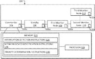
FIG. 1 is a block diagram of an example system for stateful virtual stack recovery. A networking system 100, may include a plurality of network devices 104-112. The plurality of network devices 104-112 may be connected via a communication link to form a single virtual device, also known as a stack. The communication link may be a physical link, such as Ethernet, a wireless link, etc.
A communication link may a logical interface that connects VSF member devices. The physical interfaces assigned to the communication link may automatically form an aggregate VSF link. The links may also be used to synchronize the control plane traffic that helps the VSF stack maintain its topology and state so as to behave like a single switch. The links may also carry encapsulated data plane traffic.
The network devices may, for example, be network switches with routing capabilities such that the network device is responsible for routing data along a route (or equivalently, path) in the network. The network device may perform, for example, routing of data based on routing information accessible by the router. For example, the routing information can be stored on a storage medium of the network device, or on a storage medium separate from but accessible by the network device.
As described above, virtual Stack Forwarding (VSF) is one technology which enables multiple network devices to be connected via an Ethernet link to form a stack. The devices can be connected in, for example, a chain or a ring topology to form the VSF Stack. The VSF stack can span across multiple geographical locations, such as multiple buildings. Each network device in the VSF stack may be assigned a specific role, such as a commander, a standby or a member role.
The commander node may be responsible for managing the forwarding databases, synchronizing them with the Standby and controlling all line cards including that of the Standby. The commander node may also run control and management plane protocols. The standby node is a state-full backup device for the commander node and may take control of the VSF virtual chassis if the commander node crashes. This enables the VSF virtual chassis to continue its operations seamlessly during a failure.
Each of the devices in the VSF stack other than the commander and standby nodes may become member nodes. The member nodes may not run any networking protocols and may not store state information of the network. The ports on this switch may be directly controlled and programmed by the commander switch. When a standby takes over as commander, one of the member nodes may be upgraded to standby role.
In such an implementation, when the stack is initially formed, one network device in the stack will be selected as a commander node and another one will be selected as standby node. The other devices in the stack will act as member nodes. The commander node may synchronize the configuration of the stack to the standby node and/or one or more of the other member nodes, so that in the event of failure of the commander node, the standby (or other) node can take over as the commander node with minimal interruption of service.
The system 100 includes an example VSF stack including network devices designated as a commander device 104, a standby device 106, a first member node 108, a second member node 110 and a third member node 112. Each of these network devices may have a corresponding local database, 104 a-112 a, respectively. The local database may be a centralized database, storing the state and configuration of the network switch as well as state and configuration of other devices of the network or of the network in general. Each device may subscribe to the local database of each other device in the stack, network, etc. to receive changes.
Each network device may store some or all of the configuration, status, states and statistics of the network, and/or other devices on the network at any given point at time. The different state data may be accessed from the database either individually (data for a given time, a given device, etc.) or in aggregate (data aggregated for particular items over a given time period, etc.).
Each network device may also have a corresponding priority value. The priority value may be, for example, a number, letter, etc. The priority value may be configured by a user, such as a network administrator to be used in determining which segment to keep active in the event of a stack split. In the example scenario depicted in FIG. 1, the standby node may have a priority value of 100, the commander node may have a priority value of 100 and each of the member nodes may have a priority value of 10.
System 100 may include a processor 120 and a memory 122 that may be coupled to each other through a communication link (e.g., a bus). Processor 120 may include a single or multiple Central Processing Units (CPU) or another suitable hardware processor(s). In some examples, memory 122 stores machine readable instructions executed by processor 120 for system 100. Memory 122 may include any suitable combination of volatile and/or non-volatile memory, such as combinations of Random Access Memory (RAM), Read-Only Memory (ROM), flash memory, and/or other suitable memory.
Memory 122 stores instructions to be executed by processor 120 including instructions for interruption detection 126, network device identification 128, priority determination 130, and/or other components. According to various implementations, system 100 may be implemented in hardware and/or a combination of hardware and programming that configures hardware. Furthermore, in FIG. 1 and other Figures described herein, different numbers of components or entities than depicted may be used. Although the processor 120 and memory 122 are depicted in FIG. 1 as part of commander 104, this is for example purposes only and each of the plurality of network devices 104-112 may have a similar processor and memory and execute instructions similar to those discussed in FIGS. 1-5
Processor 120 may execute interruption detection instructions 126 to detect, by a first network device, an interruption in the network stack of network devices connected to each other through a plurality of dedicated links, wherein the interruption splits the network stack into two or more fragments. The network stack may include three or more network devices. Multiple physical network devices in a same layer of a network may be virtualized into one Virtual Switching Framework (VSF) stack. No network devices in the network stack may be connected to an intermediary network device used for managing stack splits. For example, neither a management port nor a front-plane port of the first network device may not used to connect the first network device to an intermediary network device used for managing stack splits.
Processor 120 may execute network device identification instructions 128 to identify, by the first network device, a network device in the network stack with a highest split priority. A split priority for each network device in the network stack may be stored on each network device in the network stack, including the first network device.
Processor 120 may execute priority determination instructions 130 to determine, by the first network device, whether the network device with the highest split priority belongs to a first fragment of the network stack including the first network device. If it is determined that the network device with the highest split priority belongs to the first fragment of the network stack, processor 120 may execute priority determination instructions 130 to mark, by the first network device, the first fragment as an active fragment of the network stack. Marking may be done in a variety of ways. For example, a run time state of the fragment may be updated in a run-time state database where all run-time states are stored. Example run-time state databases may be a part of corresponding local database, 104 a-112 a, described above in reference to FIG. 1 and system 100. If previously the fragment was inactive and now it became active (because inactive has gone down), front-plane ports of one or more network switches in the fragment which were previously disabled may be enabled.
If it is determined that the network device with the highest split priority does not belongs to the first fragment of the network stack, processor 120 may execute priority determination instructions 130 to mark, by the first network device, the first fragment as an inactive fragment of the network stack. For example, a run time state of the fragment may be updated in a run-time state database where all run-time states are stored. Example run-time state databases may be a part of corresponding local database, 104 a-112 a, described above in reference to FIG. 1 and system 100.
FIG. 2 is a flow diagram of another example method for virtual stack recovery. This method may be performed by each network device in a network stack, such as network devices 104-112 depicted in system 100 of FIG. 1. The method 200 may begin at block 202 and proceed to block 204 where the method may include detecting a stack split. Detecting a stack split may be done in a variety of ways. For example, if a link connecting Commander 104 and the standby 106 goes down, the commander 104 may detect that the standby is no longer reachable via the link. Likewise, the standby may detect that the commander is no longer reachable via the link and thus the standby 106 may become the new commander for the fragment containing devices 106-112. The stack may split into multiple fragments and each spilt fragment may have all the configuration and state to operate as a stack by itself.
At block 206, the method may include determining if priority based stacking recovery is enabled. Determining if priority based stacing recovery is enabled may be done in a variety of ways. For example, the network devices, such as the network devices 104-112 of system 100 of FIG. 1, may have configuration data bases (104 a-112 a, respectively) where the user configuration is stored. When priority based stacking recovery method is enabled, such as by a system administrator, by factory default, by a user, etc, a configuration item may written/stored into the configuration database.
If it is determined that priority based stacking recovery is not enabled (NO branch of block 206), then the method may proceed to block 208, where the method may end. If it is determined that priority based stack recovery is enabled (YES branch of block 206), then at block 210, the method may include identifying the highest split priority of all members in the stack. As explained above, a split priority may be configured for each network device in the stack. Upon creation of the stack (and/or periodically during operation of the network), the split priority for each network device on the stack may be stored on each network device on the stack. Accordingly, in the event of a stack split, each member device is able to retrieve the split priority for each other member, even in the event that communication links are broken between different devices in the stack. Once a member device has retrieved the split priority for each member of the stack, the member device may compare them and determine which network device or devices have the highest split priority. The split priority may be a numerical value, or some other value. In some aspects, other data may be used as the split priority, such as address, etc.
At block 212, the method may include determining if more than device in the network stack has the highest split priority. As described above, it may be desirable to configure multiple devices to have the highest split priority, if it is desired to have multiple fragments active in the event of a stack split. If it is determined that only 1 device in the network stack has the highest split priority (NO branch of block 212), the method may proceed to block 216. If it is determined that more than 1 device in the network stack has the highest split priority (YES branch of block 212), then the method may proceed to block 214, where the method may include identifying a network device in the stack, from among the network devices having the highest split priority, with the highest secondary indicator. The determined network device is then considered to be the network device with the highest split priority.
A variety of different data may be used as a secondary indicator. In some aspects, each network device may also have a member number and this member number may be used as the secondary indicator. For example, in system 100 in FIG. 1, commander 104 may be member 1 and standby 106 may be member 2. If both devices are configured with same highest split priority network device 104 will become the active fragment since it has lowest member number.
The method may proceed to block 216, where the method may include determining whether the network device with the highest split priority belongs to the same fragment as the network device carrying out the method. As described above, the method 200 may be performed by each network device in the network stack upon detection of a stack split that splits the network into multiple fragments. Accordingly, the network device performing the method will check to determine if the network device with the highest split priority is in the same fragment as the network device performing the method. If it is determined that that the network device with the highest split priority belongs to the same fragment as the network device carrying out the method (YES branch of block 216), the method may proceed to block 218, where the method may include marking the fragment that the network device performing the method belongs to as active. The method may proceed to block 220, where the method may end.
If it is determined that that the network device with the highest split priority does not belong to the same fragment as the network device carrying out the method (NO branch of block 216), the method may proceed to block 222, where the method may include marking the fragment that the network device performing the method belongs to as inactive. If a fragment is marked as inactive, each of the front plane ports on devices in the fragment may be disabled. The method may proceed to block 224, where the method may end.
Turning again, to FIG. 1, an example scenario will be described in reference to system 100. Consider the case when the stack gets split such a way that commander node 104 and standby 106 are in one fragment and member nodes 108-112 are in a second fragment. In a traditional configuration, the second fragment that doesn't have either the commander or standby may become the active fragment because it has a larger number of devices. This, however, may be an undesirable resolution as it may cause network disturbance because there is no uplink connected to the members 3-5.
Using the systems and methods described herein, such as, for example, method 200 the fragment which has the highest priority configured member present will become active and the other fragment will become inactive. If the fragment doesn't have highest priority member configured, then it will go down. In the present example, the both the commander and standby devices have a split priority of 100 and the member devices have a split priority of 10. Accordingly, the stack fragment with the highest split priority is the first fragment and the first fragment will be active and the second fragment will not be active and will go down. With this network connectivity is not lost and users will be able to manage the network.
However, this is merely an example for illustrative purposes and the systems and method described herein can be used in situation where there are other numbers of network devices, different numbers of stack splits and different device priorities. Importantly, the systems and methods described herein work regardless of stack size, position of stack split and without the need of any intermediate device or protocol-based exchange of packets between network devices in the stack. Single or multiple fragments can be made active with this feature.
FIG. 3 is a flow diagram of another example method for virtual stack recovery. The method 300 may begin at block 302 and proceed to block 304 where the method may include detecting, by a first network device, an interruption in a network stack of network devices connected to each other through a plurality of dedicated links, wherein the interruption splits the network stack into two or more fragments. The network stack includes three or more network devices. Multiple physical network devices in a same layer of a network are virtualized into one Virtual Switching Framework (VSF) stack. No network devices in the network stack may be connected to an intermediary network device used for managing stack splits. For example, neither a management port nor a front-plane port of the first network device may not be used to connect the first network device to an intermediary network device used for managing stack split.
At block 306, the method may include identifying, by the first network device, a network device in the network stack with a highest split priority. A split priority for each network device in the network stack is stored on each network device in the network stack, including the first network device.
At block 308, the method may include determining, by the first network device, that the network device with the highest split priority belongs to a first fragment of the network stack, wherein the first network device also belongs to the first fragment of the network stack. At block 310, the method may include marking, by the first network device, the first fragment as an active fragment of the network stack. The method may proceed to block 312, where the method may end.
FIGS. 4A and 4B are flow diagrams of example method for virtual stack recovery.
In some aspects, multiple network devices may be configured with the highest split priority to allow multiple fragments to become active in the case of a stack split. For example, a network administrator may desire that a fragment that has either the commander or standby to remain active after a split. This is described in method 400.
Method 400 may begin at block 402 and proceed to block 404 where the method may include determining, by the first network device, that a second network device in a second fragment of the network stack also has the highest split priority. At block 406, the method may include marking, by the first network device, the first fragment and the second fragment as the active fragment of the network stack. The method may proceed to block 408, where the method may end.
In some aspects, multiple network devices may be configured with the highest split priority, but it is not desired for more than one fragment to be active after a stack split. This is described in method 450.
Method 450 may begin at block 452 and proceed to block 454 where the method may include identifying, by the first network device, a secondary priority indicator, for each network device in the network stack with the highest split priority. In some aspects, a secondary priority indicator may be configured for each network. In other aspects, other data may be used as the secondary priority indicator. For example, the secondary priority indicator may be the network device having the a lowest member number among the members having same highest split priority
At block 456, the method may include determining, by the first network device, a priory network device with a highest se condary priority indicator and the highest split priority. The method may proceed to block 458, where the method may end.
FIG. 5 is a block diagram of an example storage medium storing machine-readable instructions for virtual stack recovery. In the example illustrated in FIG. 5, system 500 includes a processor 502 and a machine-readable storage medium 504. In some aspects, processor 502 and machine-readable storage medium 504 may be part of an Application-specific integrated circuit (ASIC). Although the following descriptions refer to a single processor and a single machine-readable storage medium, the descriptions may also apply to a system with multiple processors and multiple machine-readable storage mediums. In such examples, the instructions may be distributed (e.g., stored) across multiple machine-readable storage mediums and the instructions may be distributed (e.g., executed by) across multiple processors.
Processor 502 may be at least one central processing unit (CPU), microprocessor, and/or other hardware devices suitable for retrieval and execution of instructions stored in machine-readable storage medium 504. In the example illustrated in FIG. 5, processor 502 may fetch, decode, and execute instructions 506, 508, 510 and 512. Processor 502 may include at least one electronic circuit comprising a number of electronic components for performing the functionality of at least one of the instructions in machine-readable storage medium 504. With respect to the executable instruction representations (e.g., boxes) described and shown herein, it should be understood that part or all of the executable instructions and/or electronic circuits included within one box may be included in a different box shown in the figures or in a different box not shown.
Machine-readable storage medium 504 may be any electronic, magnetic, optical, or other physical storage device that stores executable instructions. Thus, machine-readable storage medium 504 may be, for example, Random Access Memory (RAM), an Electrically-Erasable Programmable Read-Only Memory (EEPROM), a storage drive, an optical disc, and the like. Machine-readable storage medium 504 may be disposed within system 500, as shown in FIG. 5. In this situation, the executable instructions may be “installed” on the system 500. Machine-readable storage medium 504 may be a portable, external or remote storage medium, for example, that allows system 500 to download the instructions from the portable/external/remote storage medium. In this situation, the executable instructions may be part of an “installation package”. As described herein, machine-readable storage medium 504 may be encoded with executable instructions for context aware data backup. The machine-readable storage medium may be non-transitory.
Referring to FIG. 5, interruption detect instructions 506, when executed by a processor (e.g., 502), may cause system 500 to detect, by a first network device, an interruption in a network stack of network devices connected to each other through a plurality of dedicated links, wherein the interruption splits the network stack into two or more fragments. The network stack may include three or more network devices.
Multiple physical network devices in a same layer of a network may be virtualized into one Virtual Switching Framework (VSF) stack. No network devices in the network stack may be connected to an intermediary network device used for managing stack splits. For example, neither a management port and a front-plane port of the first network device may not be used to connect the first network device to an intermediary network device used for managing stack splits.
Network device instructions 508, when executed by a processor (e.g., 502), may cause system 500 to identify, by the first network device, a network device in the network stack with a highest split priority. A split priority for each network device in the network stack may be stored on each network device in the network stack, including the first network device
Priority determine instructions 510, when executed by a processor (e.g., 502), may cause system 500 to determine, by the first network device, that the network device with the highest split priority does not belong to a first fragment of the network stack, wherein the first network device also belongs to the first fragment of the network stack.
Fragment mark instructions 512, when executed by a processor (e.g., 502), may cause system 500 to mark, by the first network device, the first fragment as an inactive fragment of the network stack.
The foregoing disclosure describes a number of examples for virtual stack recovery. The disclosed examples may include systems, devices, computer-readable storage media, and methods for virtual stack recovery. For purposes of explanation, certain examples are described with reference to the components illustrated in FIGS. 1-5. The content type of the illustrated components may overlap, however, and may be present in a fewer or greater number of elements and components. Further, all or part of the content type of illustrated elements may co-exist or be distributed among several geographically dispersed locations. Further, the disclosed examples may be implemented in various environments and are not limited to the illustrated examples.
Further, the sequence of operations described in connection with FIGS. 1-5 are examples and are not intended to be limiting. Additional or fewer operations or combinations of operations may be used or may vary without departing from the scope of the disclosed examples. Furthermore, implementations consistent with the disclosed examples need not perform the sequence of operations in any particular order. Thus, the present disclosure merely sets forth possible examples of implementations, and many variations and modifications may be made to the described examples.

Claims (20)

The invention claimed is:
1. A method comprising:
detecting, by a network device, an interruption in a network stack of network devices coupled to each other through a plurality of links, wherein a split priority value is allocated to a respective network device of the network stack, and wherein the interruption splits the network stack into two or more fragments;
in response to detecting the interruption, identifying, by the network device, a first network device with a highest split priority value in the network stack;
determining, by the network device, that the first network device with the highest split priority belongs to a first fragment of the network stack; and
in response to the network device belonging to the first fragment, marking, by the network device, the first fragment as an active fragment of the network stack.
2. The method of claim 1, wherein a split priority for each network device in the network stack is stored on each network device in the network stack.
3. The method of claim 1, wherein a subset of the network devices in a same layer of a network are virtualized into a Virtual Switching Framework (VSF) stack.
4. The method of claim 1, wherein the network devices in the network stack are not connected to an intermediary network device used for managing stack splits.
5. The method of claim 1, wherein a front-plane port of the network device is not coupled to an intermediary network device used for managing stack splits.
6. The method of claim 1, further comprising:
determining, by the network device, that a second network device in a second fragment of the network stack is associated with the highest split priority value.
7. The method of claim 6, further comprising:
marking, by the network device, the first fragment and the second fragment as the active fragment of the network stack.
8. The method of claim 6, further comprising:
identifying, by the network device, a secondary priority indicator for the first and second network devices.
9. The method of claim 8, wherein determining the first fragment as the active fragment of the network stack further comprises:
determining, by the network device, that the first network device is associated with a highest secondary priority indicator and the highest split priority value.
10. A non-transitory machine-readable storage medium encoded with instructions, the instructions executable by a processor of a system to cause the system to:
detect, by a network device, an interruption in a network stack of network devices coupled to each other through a plurality of links, wherein a split priority value is allocated to a respective network device of the network stack, and wherein the interruption splits the network stack into two or more fragments;
in response to detecting the interruption, identify, by the network device, a first network device with a highest split priority value in the network stack;
determine, by the network device, that the first network device with the highest split priority belongs to a first fragment of the network stack; and
in response to the network device belonging to the first fragment, mark, by the network device, the first fragment as an active fragment of the network stack.
11. The non-transitory computer-readable storage medium of claim 10, the instructions executable by the processor to further cause the system to:
determine, in response to the network device not belonging to the first fragment, that the network device belongs in a second fragment of the network stack; and
mark, by the network device, the second fragment as an inactive fragment of the network stack.
12. The non-transitory computer-readable storage medium of claim 10, the instructions executable by the processor to further cause the system to:
determine, by the first network device, that a third network device in a third fragment of the network stack is associated with the highest split priority value; and
mark, by the first network device, the first segment and the third fragment as the active fragment of the network stack.
13. The non-transitory computer-readable storage medium of claim 10, the instructions executable by the processor to further cause the system to:
determine, by the network device, that multiple network devices in the network stack are associated with the highest split priority value; and
identify, by the network device, a secondary priority indicator, for each of the multiple network devices; and
wherein determining the first fragment as the active fragment of the network stack further comprises determining, by the network device, that the first network device is associated with with a highest secondary priority indicator and the highest split priority.
14. The non-transitory computer-readable storage medium of claim 10 wherein the network devices in the network stack are not connected to an intermediary network device used for managing stack splits.
15. The method of claim 10, further comprising:
determining, in response to the network device not belonging to the first fragment, that the network device belongs in a second fragment of the network stack; and
marking, by the network device, the second fragment as an inactive fragment of the network stack.
16. A system comprising:
a processor; and
a memory storing instructions that when executed by the processor cause the system to:
detect, by a network device, an interruption in a network stack of network devices coupled to each other through a plurality of links, wherein a split priority value is allocated to a respective network device of the network stack, and wherein the interruption splits the network stack into two or more fragments;
in response to detecting the interruption, identify, by the network device, a first network device with a highest split priority value in the network stack;
determine, by the network device, that the first network device with the highest split priority belongs to a first fragment of the network stack; and
in response to the network device belonging to the first fragment, mark, by the network device, the first fragment as an active fragment of the network stack.
17. The system of claim 16 wherein a split priority for each network device in the network stack is stored on each network device in the network stack.
18. The system of claim 16 wherein a subset of the network devices in a same layer of a network are virtualized into Virtual Switching Framework (VSF) stack.
19. The system of claim 16 wherein a front-plane port of the network device is not coupled to an intermediary network device used for managing stack splits.
20. The system of claim 16, wherein the instructions that when executed by the processor cause the system further to:
determine, in response to the network device not belonging to the first fragment, that the network device belongs in a second fragment of the network stack; and
mark, by the network device, the second fragment as an inactive fragment of the network stack.
US16/742,042 2019-01-24 2020-01-14 Virtual stack recovery Active 2040-07-04 US11310097B2 (en)

Applications Claiming Priority (2)

Application Number Priority Date Filing Date Title
IN201941003074 2019-01-24

Publications (2)

Publication Number Publication Date
US20200244515A1 US20200244515A1 (en) 2020-07-30
US11310097B2 true US11310097B2 (en) 2022-04-19

Family

ID=71731719

Family Applications (1)

Application Number Title Priority Date Filing Date
US16/742,042 Active 2040-07-04 US11310097B2 (en) 2019-01-24 2020-01-14 Virtual stack recovery

Country Status (1)

Country Link
US (1) US11310097B2 (en)

Families Citing this family (3)

* Cited by examiner, † Cited by third party
Publication number Priority date Publication date Assignee Title
CN112104712B (en) * 2020-08-31 2022-08-30 新华三技术有限公司 Stacking system member equipment and remote management method thereof
CN112636955A (en) * 2020-12-10 2021-04-09 锐捷网络股份有限公司 Stacking double-hanging processing method and device
CN115396385B (en) * 2021-05-19 2023-07-21 中国移动通信集团浙江有限公司 Method and device for quickly recovering service of stack switch and computing equipment

Citations (5)

* Cited by examiner, † Cited by third party
Publication number Priority date Publication date Assignee Title
US20100014433A1 (en) 2008-07-16 2010-01-21 Yong Wang Method for processing multiple active devices in stacking system and stacking member device
US20100329111A1 (en) 2009-06-26 2010-12-30 H3C Technologies Co., Ltd. Multi-Active Detection Method And Stack Member Device
CN102916857A (en) 2012-11-09 2013-02-06 迈普通信技术股份有限公司 Stacking and splitting quick detection method and device
CN104579809A (en) 2013-10-22 2015-04-29 华为技术有限公司 Detection method and device for stacking splitting
US20170331676A1 (en) 2014-11-12 2017-11-16 Hangzhou H3C Technologies Co., Ltd. Handling Failure Of Stacking System

Patent Citations (5)

* Cited by examiner, † Cited by third party
Publication number Priority date Publication date Assignee Title
US20100014433A1 (en) 2008-07-16 2010-01-21 Yong Wang Method for processing multiple active devices in stacking system and stacking member device
US20100329111A1 (en) 2009-06-26 2010-12-30 H3C Technologies Co., Ltd. Multi-Active Detection Method And Stack Member Device
CN102916857A (en) 2012-11-09 2013-02-06 迈普通信技术股份有限公司 Stacking and splitting quick detection method and device
CN104579809A (en) 2013-10-22 2015-04-29 华为技术有限公司 Detection method and device for stacking splitting
US20170331676A1 (en) 2014-11-12 2017-11-16 Hangzhou H3C Technologies Co., Ltd. Handling Failure Of Stacking System

Non-Patent Citations (2)

* Cited by examiner, † Cited by third party
Title
Huawei (S2750EI&S5700 Series Ethernet Switches V200R007(C00&C10); Configuration Guide—Device Management; Issue 06, Date: Dec. 29, 2017) (Year: 2017). *
Semperboni, F., "Cisco 6500 VSS Configuration," CicsoZine, Nov. 26, 2014, https://www.ciscozine.com/cisco-vss-configuration/.

Also Published As

Publication number Publication date
US20200244515A1 (en) 2020-07-30

Similar Documents

Publication Publication Date Title
US11095558B2 (en) ASIC for routing a packet
US10868757B2 (en) Efficient routing in software defined networks
US11310097B2 (en) Virtual stack recovery
US9130858B2 (en) System and method for supporting discovery and routing degraded fat-trees in a middleware machine environment
US11729048B2 (en) System and method for efficient network reconfiguration in fat-trees
US11258635B2 (en) Overlay network routing using a programmable switch
US10880124B2 (en) Offload controller control of programmable switch
US8959201B2 (en) Limiting control traffic in a redundant gateway architecture
US10855584B2 (en) Client-equipment-peering virtual route controller
US9473360B2 (en) System and method for primary switch election in peer groups
JP5941404B2 (en) Communication system, path switching method, and communication apparatus
US20150188731A1 (en) Programmable Distributed Networking
CN104919760B (en) Virtual enclosure system control protocol
EP3316555B1 (en) Mac address synchronization method, device and system
JP2020025201A (en) Transfer device, transfer system, transfer method, and program
JP6109954B2 (en) System and method for pass-through mode in a virtual chassis system
US11171810B1 (en) Misconfigured uplink identification
JP2016501463A (en) A method at a network node and a node operable in a virtual chassis system in which it is determined whether or not a management action issues a warning that triggers a virtual chassis split
US20200106693A1 (en) Stateful virtual stack forwarding
US11405352B2 (en) Fast relearning of workload MAC addresses multi-homed to active and backup gateways

Legal Events

Date Code Title Description
AS Assignment

Owner name: HEWLETT PACKARD ENTERPRISE DEVELOPMENT LP, TEXAS

Free format text: ASSIGNMENT OF ASSIGNORS INTEREST;ASSIGNORS:KOUNDINYA, CHIVUKULA;NATARAJAN, SUBHASHINI;SHIVARAM, HARISH;REEL/FRAME:051586/0902

Effective date: 20190116

FEPP Fee payment procedure

Free format text: ENTITY STATUS SET TO UNDISCOUNTED (ORIGINAL EVENT CODE: BIG.); ENTITY STATUS OF PATENT OWNER: LARGE ENTITY

STPP Information on status: patent application and granting procedure in general

Free format text: DOCKETED NEW CASE - READY FOR EXAMINATION

STPP Information on status: patent application and granting procedure in general

Free format text: NON FINAL ACTION MAILED

STPP Information on status: patent application and granting procedure in general

Free format text: RESPONSE TO NON-FINAL OFFICE ACTION ENTERED AND FORWARDED TO EXAMINER

STPP Information on status: patent application and granting procedure in general

Free format text: NOTICE OF ALLOWANCE MAILED -- APPLICATION RECEIVED IN OFFICE OF PUBLICATIONS

STPP Information on status: patent application and granting procedure in general

Free format text: PUBLICATIONS -- ISSUE FEE PAYMENT VERIFIED

STCF Information on status: patent grant

Free format text: PATENTED CASE