US1129727A - Reversing mechanism for harvesting-machines. - Google Patents
Reversing mechanism for harvesting-machines. Download PDFInfo
- Publication number
- US1129727A US1129727A US78224913A US1913782249A US1129727A US 1129727 A US1129727 A US 1129727A US 78224913 A US78224913 A US 78224913A US 1913782249 A US1913782249 A US 1913782249A US 1129727 A US1129727 A US 1129727A
- Authority
- US
- United States
- Prior art keywords
- shaft
- wheel
- crank
- harvesting
- reversing mechanism
- Prior art date
- Legal status (The legal status is an assumption and is not a legal conclusion. Google has not performed a legal analysis and makes no representation as to the accuracy of the status listed.)
- Expired - Lifetime
Links
- 230000007246 mechanism Effects 0.000 title description 13
- 238000003306 harvesting Methods 0.000 description 11
- 238000010276 construction Methods 0.000 description 3
- 229940000425 combination drug Drugs 0.000 description 1
- 230000001276 controlling effect Effects 0.000 description 1
Images

Classifications
-
- F—MECHANICAL ENGINEERING; LIGHTING; HEATING; WEAPONS; BLASTING
- F16—ENGINEERING ELEMENTS AND UNITS; GENERAL MEASURES FOR PRODUCING AND MAINTAINING EFFECTIVE FUNCTIONING OF MACHINES OR INSTALLATIONS; THERMAL INSULATION IN GENERAL
- F16H—GEARING
- F16H1/00—Toothed gearings for conveying rotary motion
- F16H1/02—Toothed gearings for conveying rotary motion without gears having orbital motion
- F16H1/04—Toothed gearings for conveying rotary motion without gears having orbital motion involving only two intermeshing members
- F16H1/12—Toothed gearings for conveying rotary motion without gears having orbital motion involving only two intermeshing members with non-parallel axes
- F16H1/16—Toothed gearings for conveying rotary motion without gears having orbital motion involving only two intermeshing members with non-parallel axes comprising worm and worm-wheel
-
- Y—GENERAL TAGGING OF NEW TECHNOLOGICAL DEVELOPMENTS; GENERAL TAGGING OF CROSS-SECTIONAL TECHNOLOGIES SPANNING OVER SEVERAL SECTIONS OF THE IPC; TECHNICAL SUBJECTS COVERED BY FORMER USPC CROSS-REFERENCE ART COLLECTIONS [XRACs] AND DIGESTS
- Y10—TECHNICAL SUBJECTS COVERED BY FORMER USPC
- Y10T—TECHNICAL SUBJECTS COVERED BY FORMER US CLASSIFICATION
- Y10T74/00—Machine element or mechanism
- Y10T74/19—Gearing
- Y10T74/19614—Disconnecting means
Definitions
- SHEETSSHEET 14 wnwesses INVENTOR I ATTORNEYS THE NORRIS PErFRs co PHOTOJJTHO WASHINGION, D.
- WITN ESjES ATTORNEYS THE NORRIS PETERS Ca. PHGTO-LITHCL. WASHING ION, D. C
- a spurwheel, pin-wheel, bevel-wheel or the like connected with the driving wheel by a chain gear, is driven by a machine element (preferably a worm or bevel wheel) which is fixed on an auxiliary movable shaft.
- a machine element preferably a worm or bevel wheel
- a crank is hinged, by means of which the shaft, and, therefore, also the machine element, can be simultaneously turned, and, on pressing down said crank, brought into engagement with the spur-wheel or the like
- the shaft is raised again by a spring and the machine element thus moved out of engagement with the spur-wheel or the like.
- the advantage of the device consists in the fact that by the application of a comparatively small amount of force applied near the seat the mowing or harvesting machine can be run backward from the drivers seat and in the automatic release effected before the machine commences its forward motion thus preventing the parts from being broken.
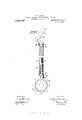
- Figure 1 is a sectional side elevation of my improvement.
- Fig. 2 is a plan view of a portion of same.
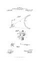
- Fig. 3 is a side elevation showing connections with a mowing machine drive wheel.
- Fig. f is a sectional plan view of Fig. 3.
- Figs. 5 and 6 are sectional elevations of a modified form in a position of rest and of use, respectively.
- a (Figs 1-4) is a spur-wheel connected with the chain wheel 7), which spur-wheel is to be turned by a spiral thread 0
- the disk 0 carrying said spiral thread 0 is secured to'the shaft d, which is adapted to be moved longitudinally in the pipe 6, being commonly kept in a raised position by the spring f.
- the shaft (Z is journaled in the pipe 6 at g and h.
- the lower hearing or guide ring 9 is welded into the pipe 6, while the upper ring it fits on the top rectangular end of said shaft 03 and turns in the casing or sleeve e, a longitudinal motion being prevented by the set screw is Specification of Letters Patent.
- a bevel wheel a is secured to the chain-wheel b, which drives the main wheel 0 of the machine by a chain in known manner.
- a second bevel wheel 0 is fastened to the shaft d, which, as in the construction shown in. Figs. 1%, is adapted to be movedlongitudinally. By axial movement of this shaft the bevel wheel 0 will be brought into engagement with the bevel wheel a, normally, however, the wheel 0 is held by the spring f in the disengaged position.
- the shaft d is turned by a crank Z, which, in the position of rest (Fig. 1), hangs inoperative,
- the herein described reversing mechanism comprising in combination, a rotary machine element adapted to be secured to the driving gear of a harvesting machine, a shaft, a rotary machine element carried thereby, a stationary member supporting the shaft, and means rotatably carried by the stationary member to impart an axial and rotary motion to said shaft.
- the herein described reversing mechanism comprising in combination a machine element adapted to be secured to the driving gear of a harvester, a shaft, a machine element carried thereby, a stationary member supporting said shaft, and means rotatably carried by said stationary member to impart an axial and rotary motion to said shaft.
- the herein described reversing mechanism comprising in combination, a machine element adapted to be secured to the driving gear of a harvester, a shaft, a casing carrying said shaft, a machine element secured to said shaft, and means swiveled in said casing for engaging said shaft and imparting there to a longitudinal and rotary movement whereby the aforesaid machine elements may bebrought into contact.
- the described reversing mechanism comprising in combination, a machine element adapted to be secured to the driving gear of a harvesting machine, a shaft adapted tobe turned and moved longitudinally, a machine element secured to said shaft, a cas inginclosing said shaft, and a crank adapt- Ted to engage said shaft and be turned'in said casing and thus to turn said shaft, substantially as, and for the purpose, set forth.
- Theherein described reversing mechanism comprising in combination a gear wheel adapted to be secured to the driving gear of a harvesting machine, a shaft, a gear wheel carried at one end of said shaft, a stationary support for said casing, and a pivoted crank swiveled in said support at the opposite end of the shaft, whereby a rotary and longitudinal motion may be imparted to the shaft to cause the aforesaid gear wheels to mesh.
- the herein described reversing mecha nism comprising in combination a pinion adapted to be secured to the driving chain wheel of a mowing or harvesting machine, a shaft adapted to be moved longitudinally and rotated, a casing inclosing said shaft, a crank arm rotatably mountedin said casing and pivoted therein whereby it is adapted to be swung into engagement with the aforesaid shaft, a spring within said casing and con trolling said shaft, a spiral worm secured to the lower end of the shaft and adapted for engagement with the spur wheel on the sprocket chain shaft.
- the herein described reversing mechanism for moving a mowing or harvesting machine backward comprising in combina tion, a spur wheel adapted to be secured-to the chain wheel shaft of a mowing or harvesting machine, a shaft adapted to be moved longitudinally and rotated, a casing inclosing said shaft, a collar fitting the upper end of the shaft and rotatably held in the casing, a crank arm pivotally mounted on said collar and adapted to engage the upper end of the aforesaid shaft to cause longitudinal and rotary movement of the same, and a spiral worm wheel on the lower end of theshaft adapted to engage the spur wheel on the chain wheel shaft.
- a gear wheel adapted to be secured to the driving gear of a harvesting machine, a shaft, a gear wheel carried at one end of said shaft, a casing inclosing said shaft, a collar swiveled in said casing and slidably supporting the opposite end of said shaft, a crank pivoted to said collar at one side, and a projection at the opposite side of said collar adapted to be engaged by said crank whereby the shaft may be moved longitudinally and rotated by said crank.
Landscapes
- Harvester Elements (AREA)
- Engineering & Computer Science (AREA)
- General Engineering & Computer Science (AREA)
- Mechanical Engineering (AREA)
Description
H. QUEGWER.
REVERSING MEGHANlSM FOR HARVESTING MACHINES. APPLICATION FILED JULY 31, 1913.
1,1 29,727. Patented Feb. 23, 1915.
3 SHEETSSHEET 14 wnwesses INVENTOR I ATTORNEYS THE NORRIS PErFRs co PHOTOJJTHO WASHINGION, D.
H. QUEGWER. REVEHSING MECHANISM FOR HARVESTING MACHINES.
3 SHEETS-SHEET 2.
Patented Feb. 23, 1915.
- :IlI:=I=:l===I 0" APPLIGATION FILED JULY 31, 1913.
WITN ESjES ATTORNEYS THE NORRIS PETERS Ca. PHGTO-LITHCL. WASHING ION, D. C
H. QUEGWER.
REVERSING MECHANISM FOR HARVESTING MACHINES.
APPLICATION FILED JULY 31, 1913.
Patented Feb. 23, 1915.
3 SHEETS'SHEET 3.
Z N. mm 1N m mw WITNESSES AT TOFFNEYS connected with the driving wheel.
HERMANN QUEGVVER, 01E BUNZLAU, GERMANY.
REVERSING MECHANISM FOR HARVESTING-MACHINES.
Application filed. July 31, 1913.
To all whom it may concern Be it known that I, HERMANN QUEGWER, a subject of the King of Prussia, residing at Bunzlau, Silesia, in the Kingdom of Prussia and German Empire, have invented a new and useful Improved Reversing Mechanism for Harvesting-Machines, of which the following is a specification.
In the machine forming the subjectmatter of the present invention a spurwheel, pin-wheel, bevel-wheel or the like, connected with the driving wheel by a chain gear, is driven by a machine element (preferably a worm or bevel wheel) which is fixed on an auxiliary movable shaft. To this shaft a crank is hinged, by means of which the shaft, and, therefore, also the machine element, can be simultaneously turned, and, on pressing down said crank, brought into engagement with the spur-wheel or the like As soon as the crank is released, the shaft is raised again by a spring and the machine element thus moved out of engagement with the spur-wheel or the like.
The advantage of the device consists in the fact that by the application of a comparatively small amount of force applied near the seat the mowing or harvesting machine can be run backward from the drivers seat and in the automatic release effected before the machine commences its forward motion thus preventing the parts from being broken.
In the drawings Figure 1 is a sectional side elevation of my improvement. Fig. 2 is a plan view of a portion of same. Fig. 3 is a side elevation showing connections with a mowing machine drive wheel. Fig. f is a sectional plan view of Fig. 3. Figs. 5 and 6 are sectional elevations of a modified form in a position of rest and of use, respectively.
a (Figs 1-4) is a spur-wheel connected with the chain wheel 7), which spur-wheel is to be turned by a spiral thread 0 The disk 0 carrying said spiral thread 0 is secured to'the shaft d, which is adapted to be moved longitudinally in the pipe 6, being commonly kept in a raised position by the spring f. The shaft (Z is journaled in the pipe 6 at g and h. Preferably the lower hearing or guide ring 9 is welded into the pipe 6, while the upper ring it fits on the top rectangular end of said shaft 03 and turns in the casing or sleeve e, a longitudinal motion being prevented by the set screw is Specification of Letters Patent.
Patented Feb. 23, 1915.
Serial No. 782,249.
projecting into the groove 2'. To the ring it a pin is secured, on which one end of the crank Z is hinged. This crank has a projection m, which, on turning down said crank, presses on the top end of the shaft d and moves said shaft against the pressure of the spring f so far downward, that the spiral thread 0 comes into engagement with the spur-wheel a. By turning the crank Z the shaft 61 and disk 0 are likewise turned, so that the spur-wheel a is driven with a corresponding purchase. On releasing the crank [the shaft d is raised by the spring f, so that, when the machine is moved forward, said spur-wheel a can turn in the opposite -direction to that in which it previously turned.
In the construction shown in Figs. 5 and 6 a bevel wheel a is secured to the chain-wheel b, which drives the main wheel 0 of the machine by a chain in known manner. A second bevel wheel 0 is fastened to the shaft d, which, as in the construction shown in. Figs. 1%, is adapted to be movedlongitudinally. By axial movement of this shaft the bevel wheel 0 will be brought into engagement with the bevel wheel a, normally, however, the wheel 0 is held by the spring f in the disengaged position. In this construction also the shaft d is turned by a crank Z, which, in the position of rest (Fig. 1), hangs inoperative,
while on turning the crank Z into the position shown in F ig. 6 said crank presses down the shaft (Z, so that the bevel wheel 0 comes into engagement with the wheel a. On again releasing the crank Z the shaft at will be raised automatically by the spring 7 and consequently the bevel wheels will be moved outof engagement.
What I claim and desire to secure by Letters Patent of the United States is 1. The herein described reversing mechanism comprising in combination, a rotary machine element adapted to be secured to the driving gear of a harvesting machine, a shaft, a rotary machine element carried thereby, a stationary member supporting the shaft, and means rotatably carried by the stationary member to impart an axial and rotary motion to said shaft.
2. The herein described reversing mechanism comprising in combination a machine element adapted to be secured to the driving gear of a harvester, a shaft, a machine element carried thereby, a stationary member supporting said shaft, and means rotatably carried by said stationary member to impart an axial and rotary motion to said shaft.
3. The herein described reversing mechanism comprising in combination, a machine element adapted to be secured to the driving gear of a harvester, a shaft, a casing carrying said shaft, a machine element secured to said shaft, and means swiveled in said casing for engaging said shaft and imparting there to a longitudinal and rotary movement whereby the aforesaid machine elements may bebrought into contact.
l. The described reversing mechanism, comprising in combination, a machine element adapted to be secured to the driving gear of a harvesting machine, a shaft adapted tobe turned and moved longitudinally, a machine element secured to said shaft, a cas inginclosing said shaft, and a crank adapt- Ted to engage said shaft and be turned'in said casing and thus to turn said shaft, substantially as, and for the purpose, set forth.
5. Theherein described reversing mechanism comprising in combination a gear wheel adapted to be secured to the driving gear of a harvesting machine, a shaft, a gear wheel carried at one end of said shaft, a stationary support for said casing, and a pivoted crank swiveled in said support at the opposite end of the shaft, whereby a rotary and longitudinal motion may be imparted to the shaft to cause the aforesaid gear wheels to mesh.
6. The herein described reversing mecha nism, comprising in combination a pinion adapted to be secured to the driving chain wheel of a mowing or harvesting machine, a shaft adapted to be moved longitudinally and rotated, a casing inclosing said shaft, a crank arm rotatably mountedin said casing and pivoted therein whereby it is adapted to be swung into engagement with the aforesaid shaft, a spring within said casing and con trolling said shaft, a spiral worm secured to the lower end of the shaft and adapted for engagement with the spur wheel on the sprocket chain shaft.
7. The herein described reversing mechanism for moving a mowing or harvesting machine backward, comprising in combina tion, a spur wheel adapted to be secured-to the chain wheel shaft of a mowing or harvesting machine, a shaft adapted to be moved longitudinally and rotated, a casing inclosing said shaft, a collar fitting the upper end of the shaft and rotatably held in the casing, a crank arm pivotally mounted on said collar and adapted to engage the upper end of the aforesaid shaft to cause longitudinal and rotary movement of the same, and a spiral worm wheel on the lower end of theshaft adapted to engage the spur wheel on the chain wheel shaft.
8. In a reversing mechanism, the combination with a gear wheel adapted to be secured to the driving gear of a harvesting machine, a shaft, a gear wheel carried at one end of said shaft, a casing inclosing said shaft, a collar swiveled in said casing and slidably supporting the opposite end of said shaft, a crank pivoted to said collar at one side, and a projection at the opposite side of said collar adapted to be engaged by said crank whereby the shaft may be moved longitudinally and rotated by said crank.
In testimony whereof I have signed my name to this specification in the presence of two subscribing witnesses.
HERMANN QUEGVVER.
Witnesses HUeo SoHwARzBAoH, GEoRG BEYER.
Copies of this patent may be obtained for five cents each, by addressing the Commissioner of Patents.
Washington, D. 0."
Priority Applications (1)
| Application Number | Priority Date | Filing Date | Title |
|---|---|---|---|
| US78224913A US1129727A (en) | 1913-07-31 | 1913-07-31 | Reversing mechanism for harvesting-machines. |
Applications Claiming Priority (1)
| Application Number | Priority Date | Filing Date | Title |
|---|---|---|---|
| US78224913A US1129727A (en) | 1913-07-31 | 1913-07-31 | Reversing mechanism for harvesting-machines. |
Publications (1)
| Publication Number | Publication Date |
|---|---|
| US1129727A true US1129727A (en) | 1915-02-23 |
Family
ID=3197861
Family Applications (1)
| Application Number | Title | Priority Date | Filing Date |
|---|---|---|---|
| US78224913A Expired - Lifetime US1129727A (en) | 1913-07-31 | 1913-07-31 | Reversing mechanism for harvesting-machines. |
Country Status (1)
| Country | Link |
|---|---|
| US (1) | US1129727A (en) |
-
1913
- 1913-07-31 US US78224913A patent/US1129727A/en not_active Expired - Lifetime
Similar Documents
| Publication | Publication Date | Title |
|---|---|---|
| US1129727A (en) | Reversing mechanism for harvesting-machines. | |
| US1184905A (en) | Automatic reversing machanism. | |
| US457731A (en) | John leeming | |
| US307844A (en) | Reversing mechanism for machinery | |
| US1168779A (en) | Attachment for pipe-dies. | |
| US853564A (en) | Tool-operating mechanism. | |
| US449525A (en) | And charles b | |
| US1067682A (en) | Dividing-head. | |
| US406327A (en) | wright | |
| US1104840A (en) | Winding-machine. | |
| US936291A (en) | Gearing. | |
| US1073055A (en) | Gearing. | |
| US1185616A (en) | Friction-drive for motor-cycles. | |
| US1270489A (en) | Mower. | |
| US1115568A (en) | Reversing mechanism. | |
| US1164116A (en) | Machine-brake. | |
| US1289031A (en) | Self-starting attachment for automobiles. | |
| US575050A (en) | Half to james p | |
| US925769A (en) | Gearing. | |
| US1315434A (en) | Operating mechanism fob- swing-saws | |
| US1322351A (en) | Clutch and actuating mechanism | |
| US754818A (en) | Trimming-machine. | |
| US1099859A (en) | Water elevating and impelling apparatus. | |
| US1106449A (en) | Automobile-starter. | |
| US735701A (en) | Speed-changing mechanism for automatic lathes. |