US11293341B2 - Internal combustion engine for a motor vehicle, more particularly for a motor car, and method for operating such an internal combustion engine - Google Patents
Internal combustion engine for a motor vehicle, more particularly for a motor car, and method for operating such an internal combustion engine Download PDFInfo
- Publication number
- US11293341B2 US11293341B2 US17/055,913 US201917055913A US11293341B2 US 11293341 B2 US11293341 B2 US 11293341B2 US 201917055913 A US201917055913 A US 201917055913A US 11293341 B2 US11293341 B2 US 11293341B2
- Authority
- US
- United States
- Prior art keywords
- exhaust gas
- bypass line
- turbine wheel
- internal combustion
- combustion engine
- Prior art date
- Legal status (The legal status is an assumption and is not a legal conclusion. Google has not performed a legal analysis and makes no representation as to the accuracy of the status listed.)
- Active
Links
Images


Classifications
-
- F—MECHANICAL ENGINEERING; LIGHTING; HEATING; WEAPONS; BLASTING
- F01—MACHINES OR ENGINES IN GENERAL; ENGINE PLANTS IN GENERAL; STEAM ENGINES
- F01N—GAS-FLOW SILENCERS OR EXHAUST APPARATUS FOR MACHINES OR ENGINES IN GENERAL; GAS-FLOW SILENCERS OR EXHAUST APPARATUS FOR INTERNAL-COMBUSTION ENGINES
- F01N3/00—Exhaust or silencing apparatus having means for purifying, rendering innocuous, or otherwise treating exhaust
- F01N3/08—Exhaust or silencing apparatus having means for purifying, rendering innocuous, or otherwise treating exhaust for rendering innocuous
- F01N3/10—Exhaust or silencing apparatus having means for purifying, rendering innocuous, or otherwise treating exhaust for rendering innocuous by thermal or catalytic conversion of noxious components of exhaust
-
- F—MECHANICAL ENGINEERING; LIGHTING; HEATING; WEAPONS; BLASTING
- F02—COMBUSTION ENGINES; HOT-GAS OR COMBUSTION-PRODUCT ENGINE PLANTS
- F02B—INTERNAL-COMBUSTION PISTON ENGINES; COMBUSTION ENGINES IN GENERAL
- F02B37/00—Engines characterised by provision of pumps driven at least for part of the time by exhaust
- F02B37/12—Control of the pumps
- F02B37/18—Control of the pumps by bypassing exhaust from the inlet to the outlet of turbine or to the atmosphere
- F02B37/183—Arrangements of bypass valves or actuators therefor
-
- F—MECHANICAL ENGINEERING; LIGHTING; HEATING; WEAPONS; BLASTING
- F01—MACHINES OR ENGINES IN GENERAL; ENGINE PLANTS IN GENERAL; STEAM ENGINES
- F01N—GAS-FLOW SILENCERS OR EXHAUST APPARATUS FOR MACHINES OR ENGINES IN GENERAL; GAS-FLOW SILENCERS OR EXHAUST APPARATUS FOR INTERNAL-COMBUSTION ENGINES
- F01N3/00—Exhaust or silencing apparatus having means for purifying, rendering innocuous, or otherwise treating exhaust
- F01N3/02—Exhaust or silencing apparatus having means for purifying, rendering innocuous, or otherwise treating exhaust for cooling, or for removing solid constituents of, exhaust
- F01N3/021—Exhaust or silencing apparatus having means for purifying, rendering innocuous, or otherwise treating exhaust for cooling, or for removing solid constituents of, exhaust by means of filters
-
- F—MECHANICAL ENGINEERING; LIGHTING; HEATING; WEAPONS; BLASTING
- F01—MACHINES OR ENGINES IN GENERAL; ENGINE PLANTS IN GENERAL; STEAM ENGINES
- F01N—GAS-FLOW SILENCERS OR EXHAUST APPARATUS FOR MACHINES OR ENGINES IN GENERAL; GAS-FLOW SILENCERS OR EXHAUST APPARATUS FOR INTERNAL-COMBUSTION ENGINES
- F01N3/00—Exhaust or silencing apparatus having means for purifying, rendering innocuous, or otherwise treating exhaust
- F01N3/08—Exhaust or silencing apparatus having means for purifying, rendering innocuous, or otherwise treating exhaust for rendering innocuous
- F01N3/10—Exhaust or silencing apparatus having means for purifying, rendering innocuous, or otherwise treating exhaust for rendering innocuous by thermal or catalytic conversion of noxious components of exhaust
- F01N3/101—Three-way catalysts
-
- F—MECHANICAL ENGINEERING; LIGHTING; HEATING; WEAPONS; BLASTING
- F01—MACHINES OR ENGINES IN GENERAL; ENGINE PLANTS IN GENERAL; STEAM ENGINES
- F01N—GAS-FLOW SILENCERS OR EXHAUST APPARATUS FOR MACHINES OR ENGINES IN GENERAL; GAS-FLOW SILENCERS OR EXHAUST APPARATUS FOR INTERNAL-COMBUSTION ENGINES
- F01N3/00—Exhaust or silencing apparatus having means for purifying, rendering innocuous, or otherwise treating exhaust
- F01N3/08—Exhaust or silencing apparatus having means for purifying, rendering innocuous, or otherwise treating exhaust for rendering innocuous
- F01N3/10—Exhaust or silencing apparatus having means for purifying, rendering innocuous, or otherwise treating exhaust for rendering innocuous by thermal or catalytic conversion of noxious components of exhaust
- F01N3/18—Exhaust or silencing apparatus having means for purifying, rendering innocuous, or otherwise treating exhaust for rendering innocuous by thermal or catalytic conversion of noxious components of exhaust characterised by methods of operation; Control
- F01N3/20—Exhaust or silencing apparatus having means for purifying, rendering innocuous, or otherwise treating exhaust for rendering innocuous by thermal or catalytic conversion of noxious components of exhaust characterised by methods of operation; Control specially adapted for catalytic conversion
- F01N3/2053—By-passing catalytic reactors, e.g. to prevent overheating
-
- F—MECHANICAL ENGINEERING; LIGHTING; HEATING; WEAPONS; BLASTING
- F01—MACHINES OR ENGINES IN GENERAL; ENGINE PLANTS IN GENERAL; STEAM ENGINES
- F01N—GAS-FLOW SILENCERS OR EXHAUST APPARATUS FOR MACHINES OR ENGINES IN GENERAL; GAS-FLOW SILENCERS OR EXHAUST APPARATUS FOR INTERNAL-COMBUSTION ENGINES
- F01N3/00—Exhaust or silencing apparatus having means for purifying, rendering innocuous, or otherwise treating exhaust
- F01N3/08—Exhaust or silencing apparatus having means for purifying, rendering innocuous, or otherwise treating exhaust for rendering innocuous
- F01N3/10—Exhaust or silencing apparatus having means for purifying, rendering innocuous, or otherwise treating exhaust for rendering innocuous by thermal or catalytic conversion of noxious components of exhaust
- F01N3/24—Exhaust or silencing apparatus having means for purifying, rendering innocuous, or otherwise treating exhaust for rendering innocuous by thermal or catalytic conversion of noxious components of exhaust characterised by constructional aspects of converting apparatus
-
- F—MECHANICAL ENGINEERING; LIGHTING; HEATING; WEAPONS; BLASTING
- F02—COMBUSTION ENGINES; HOT-GAS OR COMBUSTION-PRODUCT ENGINE PLANTS
- F02B—INTERNAL-COMBUSTION PISTON ENGINES; COMBUSTION ENGINES IN GENERAL
- F02B39/00—Component parts, details, or accessories relating to, driven charging or scavenging pumps, not provided for in groups F02B33/00 - F02B37/00
- F02B39/02—Drives of pumps; Varying pump drive gear ratio
- F02B39/08—Non-mechanical drives, e.g. fluid drives having variable gear ratio
- F02B39/10—Non-mechanical drives, e.g. fluid drives having variable gear ratio electric
-
- F—MECHANICAL ENGINEERING; LIGHTING; HEATING; WEAPONS; BLASTING
- F01—MACHINES OR ENGINES IN GENERAL; ENGINE PLANTS IN GENERAL; STEAM ENGINES
- F01N—GAS-FLOW SILENCERS OR EXHAUST APPARATUS FOR MACHINES OR ENGINES IN GENERAL; GAS-FLOW SILENCERS OR EXHAUST APPARATUS FOR INTERNAL-COMBUSTION ENGINES
- F01N2240/00—Combination or association of two or more different exhaust treating devices, or of at least one such device with an auxiliary device, not covered by indexing codes F01N2230/00 or F01N2250/00, one of the devices being
- F01N2240/36—Combination or association of two or more different exhaust treating devices, or of at least one such device with an auxiliary device, not covered by indexing codes F01N2230/00 or F01N2250/00, one of the devices being an exhaust flap
-
- F—MECHANICAL ENGINEERING; LIGHTING; HEATING; WEAPONS; BLASTING
- F01—MACHINES OR ENGINES IN GENERAL; ENGINE PLANTS IN GENERAL; STEAM ENGINES
- F01N—GAS-FLOW SILENCERS OR EXHAUST APPARATUS FOR MACHINES OR ENGINES IN GENERAL; GAS-FLOW SILENCERS OR EXHAUST APPARATUS FOR INTERNAL-COMBUSTION ENGINES
- F01N2410/00—By-passing, at least partially, exhaust from inlet to outlet of apparatus, to atmosphere or to other device
- F01N2410/06—By-passing, at least partially, exhaust from inlet to outlet of apparatus, to atmosphere or to other device at cold starting
-
- F—MECHANICAL ENGINEERING; LIGHTING; HEATING; WEAPONS; BLASTING
- F01—MACHINES OR ENGINES IN GENERAL; ENGINE PLANTS IN GENERAL; STEAM ENGINES
- F01N—GAS-FLOW SILENCERS OR EXHAUST APPARATUS FOR MACHINES OR ENGINES IN GENERAL; GAS-FLOW SILENCERS OR EXHAUST APPARATUS FOR INTERNAL-COMBUSTION ENGINES
- F01N2590/00—Exhaust or silencing apparatus adapted to particular use, e.g. for military applications, airplanes, submarines
- F01N2590/11—Exhaust or silencing apparatus adapted to particular use, e.g. for military applications, airplanes, submarines for hybrid vehicles
-
- Y—GENERAL TAGGING OF NEW TECHNOLOGICAL DEVELOPMENTS; GENERAL TAGGING OF CROSS-SECTIONAL TECHNOLOGIES SPANNING OVER SEVERAL SECTIONS OF THE IPC; TECHNICAL SUBJECTS COVERED BY FORMER USPC CROSS-REFERENCE ART COLLECTIONS [XRACs] AND DIGESTS
- Y02—TECHNOLOGIES OR APPLICATIONS FOR MITIGATION OR ADAPTATION AGAINST CLIMATE CHANGE
- Y02A—TECHNOLOGIES FOR ADAPTATION TO CLIMATE CHANGE
- Y02A50/00—TECHNOLOGIES FOR ADAPTATION TO CLIMATE CHANGE in human health protection, e.g. against extreme weather
- Y02A50/20—Air quality improvement or preservation, e.g. vehicle emission control or emission reduction by using catalytic converters
-
- Y—GENERAL TAGGING OF NEW TECHNOLOGICAL DEVELOPMENTS; GENERAL TAGGING OF CROSS-SECTIONAL TECHNOLOGIES SPANNING OVER SEVERAL SECTIONS OF THE IPC; TECHNICAL SUBJECTS COVERED BY FORMER USPC CROSS-REFERENCE ART COLLECTIONS [XRACs] AND DIGESTS
- Y02—TECHNOLOGIES OR APPLICATIONS FOR MITIGATION OR ADAPTATION AGAINST CLIMATE CHANGE
- Y02T—CLIMATE CHANGE MITIGATION TECHNOLOGIES RELATED TO TRANSPORTATION
- Y02T10/00—Road transport of goods or passengers
- Y02T10/10—Internal combustion engine [ICE] based vehicles
- Y02T10/12—Improving ICE efficiencies
Definitions
- the invention relates to an internal combustion engine for a motor vehicle, in particular for an automobile. Furthermore, the invention relates to a method for operating such an internal combustion engine.
- the internal combustion engine comprises an exhaust system through which the exhaust gas from the internal combustion engine can flow and in which at least one exhaust gas aftertreatment element for the aftertreatment of the exhaust gas is arranged.
- the internal combustion engine comprises at least one exhaust gas turbocharger, which has a turbine and a compressor arranged in the exhaust system.
- the turbine comprises a turbine wheel which can be driven by the exhaust gas and is arranged upstream of the at least one exhaust gas aftertreatment element.
- the compressor comprises a compressor wheel which can be driven by the turbine wheel and by means of which air, which is to be supplied to at least one combustion chamber of the internal combustion engine, can be compressed.
- the internal combustion engine comprises at least one electric machine, by means of which at least the turbine wheel can be driven electrically or by an electric engine.
- a bypass device is provided, which has at least one bypass line.
- the bypass line bypasses the turbine wheel, such that the turbine wheel can be bypassed via the bypass line at least by part of the exhaust gas flowing through the exhaust system. This means that the exhaust gas flowing through the exhaust system bypasses the turbine wheel and thus does not drive the turbine wheel. In other words, the turbine wheel is not driven by the exhaust gas flowing through the bypass line.
- DE 10 2007 017 777 A1 discloses a turbocharger arrangement for a motor vehicle, having at least one turbocharger stage which has a turbine and a compressor which are mechanically decoupled from each other.
- a charged internal combustion engine is known from DE 10 2015 208 991 A1.
- the object of the present invention is to develop an internal combustion engine and a method of the type mentioned above in such a way that a particularly low-emission operation of the internal combustion engine can be implemented.
- bypass line also bypasses the at least one exhaust gas aftertreatment element such that the at least one exhaust gas aftertreatment element can also be bypassed at least by part of the exhaust gas.
- a valve arrangement is thus arranged in the bypass line, by means of which a quantity of the exhaust gas flowing through the bypass line and thereby bypassing the turbine wheel and the at least one exhaust gas aftertreatment element can be adjusted.
- the at least one exhaust gas aftertreatment element is preferably an exhaust gas aftertreatment element close to the engine, which is arranged close to the combustion chamber.
- the at least one exhaust gas aftertreatment element can have exactly one exhaust gas aftertreatment component for the aftertreatment of the exhaust gas, or the at least one exhaust gas aftertreatment element is an exhaust gas aftertreatment group which has several exhaust gas aftertreatment components for the aftertreatment of the exhaust gas.
- the at least one exhaust gas aftertreatment element has at least or exactly one catalytic converter, in particular a three-way catalytic converter.
- the at least one exhaust gas aftertreatment element is the first exhaust gas aftertreatment element of the internal combustion engine arranged downstream of the combustion chamber in the exhaust system and designed for the aftertreatment of the exhaust gas.
- the internal combustion engine is designed as a petrol engine.
- the motor vehicle is designed as a hybrid vehicle.
- the respective exhaust gas aftertreatment element can be brought to an advantageous operating temperature particularly quickly and thus for a particularly short time after a cold start or restart of the internal combustion engine, such that the exhaust gas can then be after-treated particularly well.
- a particularly low-emission operation can be guaranteed.
- the bypass line is fluidically connected to the exhaust system at a branch point arranged upstream of the turbine wheel and upstream of the at least one exhaust gas aftertreatment element, such that by means of the bypass line, at least the part of the exhaust gas at the branch point can be branched off from the exhaust system and introduced into the bypass line, wherein the bypass line is fluidically connected to the exhaust system at a discharge point arranged downstream of the turbine wheel and downstream of the at least one exhaust gas aftertreatment element, such that the exhaust gas flowing through the bypass line can be discharged from the bypass line at the discharge point and can be introduced into the exhaust system.
- At least one further exhaust gas aftertreatment element for aftertreatment of the exhaust gas in the exhaust system is arranged downstream of the discharge point.
- the further exhaust gas aftertreatment element has at least one particulate filter.
- the at least one exhaust gas aftertreatment element has a three-way catalytic converter.
- the at least one exhaust gas aftertreatment element in the direction of flow of the exhaust gas flowing through the exhaust system is the first exhaust gas aftertreatment element of the internal combustion engine arranged downstream of the combustion chamber in the exhaust system and designed for the aftertreatment of the exhaust gas.
- the bypass line also bypasses the at least one exhaust gas aftertreatment element such that the at least one exhaust gas aftertreatment element is also bypassed at least by part of the exhaust gas.
- a valve element is arranged in the bypass line, by means of which valve element a quantity of the exhaust gas flowing through the bypass line and thereby bypassing the turbine wheel and the at least one exhaust gas aftertreatment element is adjusted.
- the turbine wheel is rotated by a motor by means of the electric machine for a period of at least substantially or in approximately five seconds in a forward direction of rotation, in which the turbine wheel can be or is driven by the exhaust gas flowing through the exhaust system, in particular in a normal operation, in particular while the internal combustion engine is deactivated, if an external temperature and/or a temperature of a coolant, in particular a cooling liquid, for cooling the internal combustion engine is lower than a predetermined limit value.
- the coolant is water or comprises water, such that the coolant is also referred to as cooling water.
- the electric machine is driven by a motor in the forward direction of rotation, whereby the turbine or the turbine wheel is rotated in the forward direction of rotation.
- the method is a method for heating the at least one exhaust gas aftertreatment element and/or the aforementioned, possibly provided further exhaust gas aftertreatment element, such that a particularly low-emission operation can be guaranteed.
- valve element is opened to the maximum during the method, in particular during heating, i.e., if it is set to about the maximum opening.
- the turbine wheel is rotated by a motor by means of the electric machine in a reverse direction of rotation opposite to the forward direction of rotation, in particular while the internal combustion engine is deactivated.
- exhaust gas is conveyed from the discharge point through the at least one exhaust gas aftertreatment element and through the turbine to the branch point, for example.
- the gas flowing out of the internal combustion engine is referred to as exhaust gas, even if the internal combustion engine is deactivated, since the gas, which circulates promptly after the internal combustion engine has been switched off, is even under this operating condition, an exhaust gas from combustion processes which results from the combustion processes before the internal combustion engine has been switched off.
- the exhaust gas conveyed from the discharge point to the branch point by means of the turbine wheel can flow into the bypass line and flow via the bypass line from the branch point to the discharge point.
- the exhaust gas can flow out of the bypass line and into the exhaust system, also referred to as the exhaust tract, whereupon the exhaust gas is again conveyed by the turbine from the discharge point through the at least one exhaust gas aftertreatment element to the branch point.
- a circulation or recirculation of the exhaust gas can be effected, which in the course of the circulation or recirculation, flows from the branch point through the bypass line to the discharge point and from the discharge point back to the branch point and from there again into the bypass line, such that the exhaust gas circulates in a circle or in a circuit.
- the exhaust gas flows first through the at least one exhaust gas aftertreatment element and then though the turbine, whereupon the exhaust gas flows to the branch point and from there into the bypass line.
- the at least one exhaust gas aftertreatment element is advantageously heated up by the circulating exhaust gas, such that, for example, a particularly advantageous operating temperature of the at least one exhaust gas aftertreatment element can be set particularly quickly.
- a particularly advantageous operating temperature of the at least one exhaust gas aftertreatment element can be set particularly quickly.
- the exhaust gas is conveyed and compressed by the turbine wheel. Since the turbine as a compressor, by means of which the exhaust gas is compressed, has an advantageously low efficiency, the exhaust gas is heated up so strongly that the at least one exhaust gas aftertreatment element can be heated up advantageously.
- the electric machine In order to rotate the turbine wheel, in particular in the forward direction of rotation or the reverse direction of rotation, the electric machine is operated in an engine operation, i.e., by a motor and thus as an electric engine. Furthermore, it is conceivable that the electric machine can be operated in a generator mode and thus as a generator or by means of a generator. In the generator mode, the electric machine is driven by the turbine wheel and thus by the exhaust gas driving the turbine wheel, in particular via a shaft. In this way, the electric machine provides electrical energy or electrical current, which can be stored and/or supplied to at least one electrical consumer, in particular directly.
- FIG. 1 a schematic depiction of an internal combustion engine according to the invention
- FIG. 2 is a schematic depiction of the internal combustion engine in a recirculation mode
- FIG. 3 is a schematic depiction of the internal combustion engine according to a further embodiment
- FIG. 4 is a schematic depiction of the internal combustion engine according to a further embodiment
- FIG. 5 is a schematic depiction of the internal combustion engine according to a further embodiment.
- FIG. 6 is a schematic depiction of the internal combustion engine according to a further embodiment
- FIG. 1 shows, in a schematic depiction, an internal combustion engine 10 for a motor vehicle, which is preferably designed as an automobile, in particular a passenger car.
- the motor vehicle can be driven by means of the internal combustion engine 10 .
- the internal combustion engine 10 comprises a cylinder housing 12 , which forms or delimits several combustion chambers, present in the form of cylinders 14 .
- combustion processes take place in the cylinders 14 , resulting in exhaust gas from the internal combustion engine 10 .
- the internal combustion engine 10 has an exhaust system 16 through which the exhaust gas can flow, which is also referred to as the exhaust tract.
- the internal combustion engine 10 comprises at least one first exhaust gas aftertreatment element 18 , which is arranged in the exhaust system 16 and consequently can be flowed through by the exhaust gas.
- the exhaust gas aftertreatment element 18 is designed as a three-way catalytic converter, for example, or comprises at least or exactly one such three-way catalytic converter.
- the exhaust gas aftertreatment element 18 is the first exhaust gas aftertreatment element of the internal combustion engine 10 arranged downstream of the cylinder 14 and designed for the aftertreatment of the exhaust gas. This means that the exhaust gas can be after-treated by means of the exhaust gas aftertreatment element 18 .
- the internal combustion engine 10 comprises at least or exactly one exhaust gas turbocharger 20 .
- the exhaust gas turbocharger 20 has a turbine 22 arranged in the exhaust system 16 , which has a turbine wheel 24 arranged in the exhaust system 16 and drivable by the exhaust gas flowing through the exhaust system 16 .
- the exhaust gas turbocharger 20 comprises a compressor 28 arranged in an inlet tract 26 of the internal combustion engine 10 .
- the inlet tract 26 also referred to as the intake tract or air path, can be flowed through by air which is conducted to and into the cylinders 14 by means of the inlet tract 26 .
- the compressor 28 comprises a compressor wheel 30 arranged in the inlet tract 26 and drivable by the turbine wheel 24 , by means of which the air flowing through the inlet tract 26 is compressed or can be compressed.
- the exhaust gas turbocharger 20 comprises, for example, a shaft, to which the turbine wheel 24 and the compressor wheel 30 are or can be coupled.
- the compressor wheel 30 can be driven by the turbine wheel 24 via the shaft.
- the turbine wheel 24 can be driven or is driven by the exhaust gas, the energy contained in the exhaust gas is used to compress the air.
- the exhaust gas aftertreatment element 18 is arranged downstream of the turbine wheel 24 in the direction of flow of the exhaust gas, such that the turbine wheel 24 is arranged upstream of the exhaust gas aftertreatment element 18 .
- a charge air cooler 32 is arranged downstream of the compressor wheel 30 in the inlet tract 26 . By compressing the air, this is heated up. In order to still be able to achieve high charging levels, the air heated by the compressor and also referred to as charge air is cooled by means of the charge air cooler 32 before the charge air flows into the cylinders 14 .
- a throttle valve 34 is arranged in the intake tract 26 downstream of the charge air cooler 32 and upstream of the cylinders 14 , by means of which a quantity of the air to be supplied to the cylinders 14 and compressed can be adjusted.
- the internal combustion engine 10 also has an electric machine 36 , by means of which at least the turbine wheel 24 can be electrically driven. It is also conceivable that the compressor wheel 30 can be driven by means of the electric machine 36 . In particular, the turbine wheel 24 and/or the compressor wheel 30 can be driven electrically and thus by means of an electric engine by the electric machine 36 via the aforementioned shaft, in particular in a motor operation of the electric machine 36 .
- the internal combustion engine 10 comprises a bypass device 38 , which has at least or exactly one bypass line 40 .
- the bypass line 40 is fluidically connected to the exhaust system 16 at a branch point A arranged upstream of the turbine wheel 24 and at a discharge point E arranged downstream of the exhaust gas aftertreatment element 18 .
- at least part of the exhaust gas from the cylinders 14 flowing through the exhaust system 16 can be diverted from the exhaust system 16 by means of the bypass line 40 at the branch point A and fed into the bypass line 40 .
- the branched off exhaust gas flowing into the bypass line 40 flows through the bypass line 40 and thus from the branch point A to the discharge point E.
- the branched off exhaust gas flowing through the bypass line 40 can flow out of the bypass line 40 and flow back into the exhaust system 16 . Since the branch point A is arranged upstream of the turbine wheel 24 and the discharge point E is arranged downstream of the turbine wheel 24 , the bypass line 40 bypasses the turbine wheel 24 . This means that, via the bypass line 40 , the turbine wheel 24 can be bypassed at least by the previously mentioned exhaust gas flowing through the bypass line 40 . The exhaust gas flowing through the bypass line 40 thus bypasses the turbine wheel 24 and does not drive the turbine wheel 24 .
- the bypass line 40 is also referred to as waste gate, waste gate line, bypass or bypass line.
- the bypass line 40 also bypasses the at least one exhaust gas aftertreatment element 18 .
- the at least one exhaust gas aftertreatment element 18 can be bypassed by at least the aforementioned part of the exhaust gas.
- the discharge point E is not only arranged downstream of the turbine wheel 24 , but also downstream of the exhaust gas aftertreatment element 18 .
- the exhaust gas flowing through the bypass line 40 therefore does not flow through the exhaust gas aftertreatment element 18 .
- the bypass device 38 comprises a valve element 42 arranged in the bypass line 40 , by means of which a quantity of the exhaust gas flowing through the bypass line 40 and thereby bypassing the turbine wheel 24 and the exhaust gas aftertreatment element 18 can be adjusted or is adjusted.
- the valve element 42 is also referred as waste gate or waste gate valve.
- the exhaust gas flowing through the bypass line 40 is a so-called bypass mass flow, which is not introduced into the exhaust system 16 upstream of the exhaust gas aftertreatment element 18 , but only downstream of the exhaust gas aftertreatment element 18 . While, for example, the bypass mass flow flows through the bypass line 40 , a main exhaust gas flow or main mass flow of the exhaust gas, which is in particular larger than the bypass mass flow, flows through the turbine 22 and through the exhaust gas aftertreatment element 18 .
- the bypass mass flow is fed back to the main exhaust gas flow, such that the bypass mass flow and the main exhaust gas flow are then combined into a total flow.
- the total flow then flows from the discharge point E through the rest of the exhaust system 16 and then, for example, into the environment of the motor vehicle.
- At least one further exhaust gas aftertreatment element 44 is arranged in the exhaust system 16 downstream of the discharge point E for aftertreatment of the exhaust gas. The total mass flow thus flows through the exhaust gas aftertreatment element 44 .
- the exhaust gas aftertreatment element 44 comprises at least or exactly one particulate filter or is designed as such a particulate filter, for example.
- At least the turbine wheel 24 is driven by means of the electric machine 36 , while the internal combustion engine 10 is deactivated per se, i.e., while the internal combustion engine 10 is at a standstill. At a standstill, for example, no combustion processes take place in the cylinders 14 .
- the valve element 42 is at least partially open, preferably at maximum.
- the turbine wheel 24 is driven by means of the electric machine 26 and is thus rotated in a forward direction of rotation in which the turbine wheel 24 is driven and thus rotated during normal operation or during fired operation of the internal combustion engine 10 , for example.
- the turbine wheel 24 is driven by means of the electric machine 36 and thus rotated in a reverse direction of rotation opposite to the forward direction of rotation.
- FIG. 2 shows a circulation mode, also referred to as recirculation mode, of the internal combustion engine 10 .
- the internal combustion engine 10 is at a standstill, also referred to as engine standstill, during which no combustion processes take place in the cylinders 14 .
- the turbine wheel 24 is driven by means of the electric machine 36 and thus by an engine or electric engine and is thus preferably rotated in the forward direction of rotation while the internal combustion engine 10 is at its engine standstill and while the valve element 42 is at least partially open, in particular at maximum.
- the turbine wheel 24 conveys exhaust gas, the flow of which through the exhaust system 16 is illustrated in FIG. 2 by arrows 45 which are not crossed out.
- a circulating flow of exhaust gas is set, wherein the exhaust gas flows, in the course of its circulating flow, from the branch point A into the bypass line 40 , flows through the bypass line 40 , flows to the discharge point E, at the discharge point E flows out of the bypass line 40 and into the exhaust system 16 , then flows from the discharge point E to the branch point A and from there again into the bypass line 40 .
- the circulating exhaust gas flows through the exhaust gas aftertreatment element 18 and then through the turbine 22 .
- the turbine 22 in its function as a pump or conveying device for effecting the circulating flow, i.e., for conveying the exhaust gas, has only a poor efficiency, which is advantageous, however, in that the exhaust gas and thus the exhaust gas aftertreatment element 18 can be heated particularly advantageously and particularly quickly.
- the exhaust gas flows through the exhaust system 16 in a first flow direction which is opposite to a second flow direction in which the exhaust gas flows from the branch point A to the discharge point E during fired operation. As illustrated in FIG.
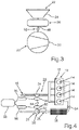
- FIG. 3 shows another embodiment of the internal combustion engine 10 .
- the previously mentioned shaft of the exhaust gas turbocharger 20 is designated 48 .
- the turbine wheel 24 is connected to the shaft 48 in a rotationally fixed manner, for example, wherein the shaft 48 and thus the turbine wheel 24 can be driven by the electric machine 36 .
- the turbine wheel 24 is rotated by means of the electric machine 36 in the forward direction of rotation, which is also referred to as the first direction of rotation.
- a reversal of the direction of rotation of the electric machine 36 is also conceivable.
- the electric machine 36 can turn the shaft 48 and thus the turbine wheel 24 in the reverse direction of rotation opposite to the forward direction of rotation, which is also referred to as the second direction of rotation.
- a coupling device 50 is provided, for example, which can be designed in particular as a freewheel.
- the turbine wheel 24 and the compressor wheel 30 are connected to each other via the coupling device 50 around the shaft 48 , in particular connected to each other in a rotationally fixed manner. If the shaft 48 is then driven by the electric machine 36 and rotated, for example, in the forward direction of rotation, both the turbine wheel 24 and the compressor wheel 30 are driven by the electric machine 36 and rotated in the forward direction of rotation.
- the compressor wheel 30 is thus driven by the coupling device 50 , which is designed to be free-wheeling, for example.
- the shaft 48 and thus the turbine wheel 24 are rotated in the reverse direction by means of the electric machine 36 .
- the compressor wheel 30 is decoupled from the shaft 48 and thus from the turbine wheel 24 , such that, for example, when the turbine wheel 24 rotates in the reverse direction, the electric machine 36 does not drive and rotate the compressor wheel 30 .
- the coupling device which is designed as a coupling element, for example, separates the compressor wheel 30 from the electric machine 36 and from the turbine wheel 24 .
- the compressor wheel 30 is not driven by the electric machine 36 and, for example, the entire engine power provided by the electric machine 36 flows into driving the turbine wheel 24 and thus into heating the exhaust gas in the exhaust system 16 .
- FIG. 4 shows another embodiment of the internal combustion engine 10 .
- a decoupled, dominantly electric exhaust turbocharger is provided.
- the electric machine 36 is assigned to the turbine wheel 24
- the compressor wheel 30 is assigned its own, additional electric machine 52 , by means of which the turbine wheel 24 can be driven, in particular electrically driven.
- An electrical shortcut is illustrated by a connection 54 shown schematically in FIG. 4 .
- the turbine 22 is decoupled from the compressor 28 or vice versa. Nevertheless, an electric motor drive of the turbine wheel 24 in the forward or reverse direction of rotation is possible.
- a respective electronic system 56 and a battery 58 are schematically depicted in FIG. 4 .
- FIG. 5 shows a further embodiment.
- An integrated starter generator 60 is provided, which can be supplied with electrical energy stored in a battery 58 via a power electronic system 62 , and/or the integrated starter generator 60 can provide electric energy, which can be stored in the battery 58 via the power electronic system 62 .
- FIG. 6 shows a further embodiment of the internal combustion engine 10 .
- a decoupling of the turbine 22 from the compressor wheel 30 and vice versa is also provided.
- the turbine wheel 24 can be rotated by means of the electric machine 36 in the forward direction of rotation and in the reverse direction of rotation, while the compressor wheel 30 is not driven by a motor.
- the invention is based in particular on the following findings: internal combustion engines have increased emission values in the exhaust gas in the first seconds of operation after a cold start, since the components of the exhaust gas aftertreatment have not yet been brought to the temperatures required for chemical exhaust gas purification. Therefore, catalytic converter heating measures are carried out, which are traditionally associated with increased fuel consumption. This leads to major disadvantages, in particular in hybridized powertrains, where the internal combustion engine, also referred to as the combustion engine, undergoes a plurality of starting processes.
- the exhaust gas turbocharger can be designed as an electrically assisted exhaust gas turbocharger and can be operated even before the internal combustion engine is actually started.
- bypass line 40 also referred to as the waste gate channel
- the turbine 22 acts as a compressor that sucks in exhaust gas from the exhaust aftertreatment components and conveys it radially outwards. If the charge exchange valves of the internal combustion engine are positioned in such a way that no flow through the cylinders is possible, the exhaust gas conveyed by the turbine 22 has no other choice than to flow through the bypass 40 and then be sucked back through the exhaust aftertreatment components and compressed again by the turbine 22 .
- the compressor 28 can rotate in an undesirable way, such that a part of the introduced electrical power is used to heat the air, also referred to as intake air. This can be avoided by decoupling the compressor 28 from the turbine 22 in the manner described above.
- the coupling device 50 is designed as a carrying clutch, coupling member or freewheel which drives the compressor wheel 30 in only one of the directions of rotation, such that the turbine wheel 24 and the compressor wheel 30 can be rotated together in one direction by the electric machine 36 .
- the turbine wheel 24 can be rotated relative to the compressor wheel 30 in the other direction of rotation opposite to the one direction of rotation, and the compressor wheel 30 is not driven if the turbine wheel 24 is rotated in the other direction of rotation.
- the other direction of rotation is, for example, forward rotation or reverse rotation.
- the turbine 22 can perform the desired heating function while the compressor 28 does not consume any power.
- the entire engine power of the electric machine 36 then flows into the compression and delivery of the exhaust gas in the recirculation mode.
- the coupling device 50 is closed, such that there is a mechanical connection between the turbine 22 , the compressor 28 and the electric machine 36 , which is designed as an electric engine, for example. If necessary, it is advantageous to adapt the blading of the turbine 22 to the particular conditions of reverse rotation.
- FIGS. 5 to 6 it is provided to divide the electrically supported exhaust gas turbocharger 20 into two completely separate components, wherein a first of the components comprises the turbine 22 , having the turbine wheel 24 , and the electric machine 36 , while the other component comprises the compressor 28 , having the compressor wheel 30 , and the electric machine 52 .
- Each component receives its own drive shaft, via which the turbine wheel 24 and the compressor wheel 30 can be driven by the respective electric machine 36 or 52 .
- the respective electric machine 36 or 52 can be operated in generator mode as well as in an engine mode. Then the turbine 22 can perform the desired heating function, while the compressor 28 does not consume any power.
- the entire engine power provided by the electric machine 36 then flows into the compression and delivery of the exhaust gas in the recirculation mode.
- the exhaust gas turbocharger 20 is designed as an electrically supported exhaust gas turbocharger.
- the recirculation operation is carried out before the actual engine start of the internal combustion engine 10 , such that, for example, the electric machine 36 is already operated before the actual engine start.
- the exhaust gas turbocharger 20 is preferably capable of running without oil pressure, since the exhaust gas turbocharger 20 is operated while the internal combustion engine 10 is at a standstill.
- the compressor side is relieved in some way, for example by a flap upstream that does not allow mass flow, a separate recirculation channel that does not allow pressure build-up, or some kind of blow-off device.
- the system is also suitable for multi-stage charged concepts, as long as the exhaust gas aftertreatment elements to be heated are incorporated in the recirculation circuit. It is also advantageous to operate the exhaust gas turbocharger 20 in the opposite direction to the conventional forward direction of rotation and thus to rotate in the reverse direction of rotation, as this results in better thermodynamic conditions for introducing electrical power into the recirculation circuit.
- the respective mechanical shaft of the exhaust gas turbocharger 20 is replaced by a chain of generator, power electronics, battery, power electronics and electric machine.
- the battery when driving downhill, the battery can be charged simultaneously via the drive wheels and the turbine, while the compressor simultaneously conditions the gas state in the intake tract.
- the compressor In the throttled combustion mode, the compressor can take over part or all of the throttling and be operated as a turbine. It is also conceivable that the two units, compressor and turbine, could be used independently of the combustion process, i.e., even when the combustion process is at a standstill, for example to condition the gas state in the intake or exhaust tract, or to heat or cool or supply engine components or components outside the engine.
Landscapes
- Engineering & Computer Science (AREA)
- Chemical & Material Sciences (AREA)
- Combustion & Propulsion (AREA)
- Mechanical Engineering (AREA)
- General Engineering & Computer Science (AREA)
- Chemical Kinetics & Catalysis (AREA)
- Health & Medical Sciences (AREA)
- Toxicology (AREA)
- Materials Engineering (AREA)
- Supercharger (AREA)
- Exhaust Gas After Treatment (AREA)
Abstract
Description
- 10 internal combustion engine
- 12 cylinder housing
- 14 cylinder
- 16 exhaust system
- 18 exhaust gas aftertreatment element
- 20 exhaust gas turbocharger
- 22 turbine
- 24 turbine wheel
- 26 inlet tract
- 28 compressor
- 30 compressor wheel
- 32 charge air cooler
- 34 throttle valve
- 36 electric machine
- 38 bypass device
- 40 bypass line
- 42 valve element
- 44 exhaust gas aftertreatment element
- 45 arrow
- 46 arrow
- 48 shaft
- 50 coupling device
- 52 electric machine
- 54 connection
- 56 electronics
- 58 battery
- 60 integrated Stator Generator
- 62 power electronics
- A branch point
- E discharge point
Claims (8)
Applications Claiming Priority (3)
| Application Number | Priority Date | Filing Date | Title |
|---|---|---|---|
| DE102018003961.8 | 2018-05-17 | ||
| DE102018003961.8A DE102018003961A1 (en) | 2018-05-17 | 2018-05-17 | Internal combustion engine for a motor vehicle, in particular for a motor vehicle, and method for operating such a combustion engine |
| PCT/EP2019/062370 WO2019219701A1 (en) | 2018-05-17 | 2019-05-14 | Internal combustion engine for a motor vehicle, more particularly for a motor car, and method for operating such an internal combustion engine |
Publications (2)
| Publication Number | Publication Date |
|---|---|
| US20210189948A1 US20210189948A1 (en) | 2021-06-24 |
| US11293341B2 true US11293341B2 (en) | 2022-04-05 |
Family
ID=66589542
Family Applications (1)
| Application Number | Title | Priority Date | Filing Date |
|---|---|---|---|
| US17/055,913 Active US11293341B2 (en) | 2018-05-17 | 2019-05-14 | Internal combustion engine for a motor vehicle, more particularly for a motor car, and method for operating such an internal combustion engine |
Country Status (4)
| Country | Link |
|---|---|
| US (1) | US11293341B2 (en) |
| CN (1) | CN112119208A (en) |
| DE (1) | DE102018003961A1 (en) |
| WO (1) | WO2019219701A1 (en) |
Families Citing this family (11)
| Publication number | Priority date | Publication date | Assignee | Title |
|---|---|---|---|---|
| DE102020004717B4 (en) * | 2020-08-05 | 2024-03-07 | Mercedes-Benz Group AG | Internal combustion engine with a recirculation circuit for heating an exhaust tract for a motor vehicle and motor vehicle |
| DE102020004729B4 (en) | 2020-08-05 | 2023-12-28 | Mercedes-Benz Group AG | Internal combustion engine for a motor vehicle and motor vehicle |
| DE102020004716B8 (en) | 2020-08-05 | 2022-06-09 | Mercedes-Benz Group AG | Internal combustion engine for a motor vehicle and motor vehicle |
| DE102020004917A1 (en) * | 2020-08-13 | 2022-02-17 | Daimler Ag | Method for operating an internal combustion engine of a motor vehicle and internal combustion engine |
| CN111963279A (en) * | 2020-09-08 | 2020-11-20 | 浙江银轮智能装备有限公司 | DPF pipeline type heated air circulation heating device |
| US11846257B2 (en) | 2021-05-03 | 2023-12-19 | Deere & Company | Engine system with reversible exhaust gas recirculation pump for controlling bypass flow |
| US11591992B2 (en) | 2021-05-05 | 2023-02-28 | Deere & Company | Engine system with air pump for enhanced turbocharger air exchange |
| US11572824B2 (en) * | 2021-05-13 | 2023-02-07 | Deere & Company | Electrified engine boost components for mitigating engine stalling in a work vehicle |
| US11536213B2 (en) | 2021-05-19 | 2022-12-27 | Deere & Company | Engine system with electrified air system components for managing emissions of nitrogen oxides in a work vehicle |
| US11572673B2 (en) | 2021-06-25 | 2023-02-07 | Deere & Company | Work vehicle power system with decoupled engine air system components |
| US11939929B2 (en) | 2021-08-19 | 2024-03-26 | Deere &Company | Engine electrified air system including electric turbocharger and exhaust gas recirculation pump |
Citations (12)
| Publication number | Priority date | Publication date | Assignee | Title |
|---|---|---|---|---|
| US20030074899A1 (en) * | 2001-10-24 | 2003-04-24 | Hitachi, Ltd. | Engine supercharging system |
| DE102007017777A1 (en) | 2007-04-16 | 2008-10-23 | Siemens Ag | Turbocharger arrangement and turbochargeable internal combustion engine |
| US20110131978A1 (en) | 2008-12-26 | 2011-06-09 | Toyota Jidosha Kabushiki Kaisha | Exhaust gas purifying apparatus for supercharger-equipped internal combustion engine |
| EP2385231A2 (en) | 2010-05-04 | 2011-11-09 | Alpraaz AB | Exhaust system for a combustion engine |
| DE102011005654A1 (en) | 2011-03-16 | 2012-09-20 | Man Diesel & Turbo Se | Internal combustion engine e.g. heavy oil powered marine diesel engine has exhaust gas bypass pipe which is guided by filter, so that exhaust gas is bypassed over bypass pipe in direction of selective catalytic reduction catalyst converter |
| US20140060006A1 (en) | 2012-08-29 | 2014-03-06 | Ford Global Technologies, Llc | Method and system for operating an engine turbocharger |
| US20150107228A1 (en) * | 2012-04-13 | 2015-04-23 | Umicore Ag & Co. Kg | Pollutant abatement system for gasoline vehicles |
| DE202015103035U1 (en) | 2015-05-15 | 2015-06-24 | Ford Global Technologies, Llc | Internal combustion engine with electrically driven turbocharger |
| JP2016011632A (en) | 2014-06-30 | 2016-01-21 | 日産自動車株式会社 | Control device for internal combustion engine |
| DE102015208991A1 (en) | 2015-05-15 | 2016-11-17 | Ford Global Technologies, Llc | Internal combustion engine with electrically driven turbocharger and method for operating such an internal combustion engine |
| US20180058287A1 (en) | 2016-08-30 | 2018-03-01 | Ford Global Technologies, Llc | Engine exhaust system control |
| US20190120180A1 (en) * | 2017-08-11 | 2019-04-25 | Ford Global Technologies, Llc | Systems and methods for particulate filter cleaning |
Family Cites Families (1)
| Publication number | Priority date | Publication date | Assignee | Title |
|---|---|---|---|---|
| DE102015201899B4 (en) | 2015-02-04 | 2021-11-04 | Bayerische Motoren Werke Aktiengesellschaft | Method for protecting a high-voltage electrical system of a motor vehicle with a first and a second energy source, computer program product and motor vehicle |
-
2018
- 2018-05-17 DE DE102018003961.8A patent/DE102018003961A1/en active Pending
-
2019
- 2019-05-14 WO PCT/EP2019/062370 patent/WO2019219701A1/en not_active Ceased
- 2019-05-14 US US17/055,913 patent/US11293341B2/en active Active
- 2019-05-14 CN CN201980032767.3A patent/CN112119208A/en active Pending
Patent Citations (17)
| Publication number | Priority date | Publication date | Assignee | Title |
|---|---|---|---|---|
| US20030074899A1 (en) * | 2001-10-24 | 2003-04-24 | Hitachi, Ltd. | Engine supercharging system |
| DE102007017777A1 (en) | 2007-04-16 | 2008-10-23 | Siemens Ag | Turbocharger arrangement and turbochargeable internal combustion engine |
| US20110131978A1 (en) | 2008-12-26 | 2011-06-09 | Toyota Jidosha Kabushiki Kaisha | Exhaust gas purifying apparatus for supercharger-equipped internal combustion engine |
| CN102187068A (en) | 2008-12-26 | 2011-09-14 | 丰田自动车株式会社 | Exhaust gas purification device for internal combustion engines with supercharger |
| US8516814B2 (en) * | 2008-12-26 | 2013-08-27 | Toyota Jidosha Kabushiki Kaisha | Exhaust gas purifying apparatus for a turbocharged internal combustion engine |
| EP2385231A2 (en) | 2010-05-04 | 2011-11-09 | Alpraaz AB | Exhaust system for a combustion engine |
| US20110271673A1 (en) * | 2010-05-04 | 2011-11-10 | Alpraaz Ab | Exhaust system for a combustion engine |
| DE102011005654A1 (en) | 2011-03-16 | 2012-09-20 | Man Diesel & Turbo Se | Internal combustion engine e.g. heavy oil powered marine diesel engine has exhaust gas bypass pipe which is guided by filter, so that exhaust gas is bypassed over bypass pipe in direction of selective catalytic reduction catalyst converter |
| US20150107228A1 (en) * | 2012-04-13 | 2015-04-23 | Umicore Ag & Co. Kg | Pollutant abatement system for gasoline vehicles |
| US20140060006A1 (en) | 2012-08-29 | 2014-03-06 | Ford Global Technologies, Llc | Method and system for operating an engine turbocharger |
| CN103670675A (en) | 2012-08-29 | 2014-03-26 | 福特环球技术公司 | Method and system for operating an engine turbocharger |
| JP2016011632A (en) | 2014-06-30 | 2016-01-21 | 日産自動車株式会社 | Control device for internal combustion engine |
| DE202015103035U1 (en) | 2015-05-15 | 2015-06-24 | Ford Global Technologies, Llc | Internal combustion engine with electrically driven turbocharger |
| DE102015208991A1 (en) | 2015-05-15 | 2016-11-17 | Ford Global Technologies, Llc | Internal combustion engine with electrically driven turbocharger and method for operating such an internal combustion engine |
| US20180058287A1 (en) | 2016-08-30 | 2018-03-01 | Ford Global Technologies, Llc | Engine exhaust system control |
| CN107795357A (en) | 2016-08-30 | 2018-03-13 | 福特环球技术公司 | Engine exhaust system controls |
| US20190120180A1 (en) * | 2017-08-11 | 2019-04-25 | Ford Global Technologies, Llc | Systems and methods for particulate filter cleaning |
Non-Patent Citations (2)
| Title |
|---|
| Chinese-language Office Action issued in Chinese Application No. 201980032767.3 dated Nov. 3, 2021 with English translation (12 pages). |
| PCT/EP2019/062370, International Search Report dated Jun. 26, 2019 (Two (2) pages). |
Also Published As
| Publication number | Publication date |
|---|---|
| US20210189948A1 (en) | 2021-06-24 |
| WO2019219701A1 (en) | 2019-11-21 |
| CN112119208A (en) | 2020-12-22 |
| DE102018003961A1 (en) | 2019-11-21 |
Similar Documents
| Publication | Publication Date | Title |
|---|---|---|
| US11293341B2 (en) | Internal combustion engine for a motor vehicle, more particularly for a motor car, and method for operating such an internal combustion engine | |
| US8739531B2 (en) | Hybrid power plant with waste heat recovery system | |
| RU2580981C2 (en) | Supercharged internal combustion engine cooling system | |
| CN102562236B (en) | Engine waste heat recovery and cooling device | |
| US10330033B2 (en) | Method and system for exhaust heat recovery | |
| JP5293236B2 (en) | Diesel engine starting method and apparatus | |
| RU2426001C2 (en) | Internal combustion engine with cooler running on recirculated waste gases | |
| US11162460B2 (en) | Methods and systems for an engine with exhaust gas recirculation | |
| JP5918722B2 (en) | Diesel engine and method for improving output of the diesel engine | |
| US11959409B2 (en) | Internal-combustion-engine warm-up apparatus | |
| JP2013032751A (en) | Engine system | |
| CN111648880A (en) | Engine with electric compressor supercharging and special exhaust gas recirculation system | |
| CN111878209B (en) | Efficient hybrid engine cooling system and engine cooling method | |
| WO2019078213A1 (en) | Cooling control device for internal combustion engine | |
| JP5831430B2 (en) | Internal combustion engine | |
| EP2483092A1 (en) | System and method for monitoring the temperature of the passenger compartment of a motor vehicle | |
| JP2010121596A (en) | Exhaust emission control system | |
| JP3630001B2 (en) | Intake heating system | |
| US20250196578A1 (en) | Cooling system for hybrid vehicle | |
| CN212337426U (en) | High-efficient thoughtlessly moves engine cooling system | |
| CN121671263A (en) | Intake air compressor and charge air cooler as heat sources for hybrid vehicles | |
| JP3921835B2 (en) | Vehicle heating device and exhaust gas recirculation device | |
| WO2023187853A1 (en) | Diagnostic method for vehicle cooling system and diagnostic device for vehicle cooling system | |
| CN116438368A (en) | Method and system for managing an active SCR device of an aftertreatment system ATS | |
| FR2926600A1 (en) | Internal combustion engine e.g. stratify direct injection type engine, for motor vehicle, has exhaust gas recycling circuit emerging in exhaust circuit downstream of thermal contact between evaporator and exhaust circuit |
Legal Events
| Date | Code | Title | Description |
|---|---|---|---|
| FEPP | Fee payment procedure |
Free format text: ENTITY STATUS SET TO UNDISCOUNTED (ORIGINAL EVENT CODE: BIG.); ENTITY STATUS OF PATENT OWNER: LARGE ENTITY |
|
| STPP | Information on status: patent application and granting procedure in general |
Free format text: DOCKETED NEW CASE - READY FOR EXAMINATION |
|
| STPP | Information on status: patent application and granting procedure in general |
Free format text: NON FINAL ACTION MAILED |
|
| AS | Assignment |
Owner name: DAIMLER AG, GERMANY Free format text: ASSIGNMENT OF ASSIGNORS INTEREST;ASSIGNORS:KUHN, THOMAS;BRINKERT, NILS;ERNST, RENE;SIGNING DATES FROM 20201110 TO 20201210;REEL/FRAME:057210/0114 |
|
| STPP | Information on status: patent application and granting procedure in general |
Free format text: RESPONSE TO NON-FINAL OFFICE ACTION ENTERED AND FORWARDED TO EXAMINER |
|
| STPP | Information on status: patent application and granting procedure in general |
Free format text: NOTICE OF ALLOWANCE MAILED -- APPLICATION RECEIVED IN OFFICE OF PUBLICATIONS |
|
| STPP | Information on status: patent application and granting procedure in general |
Free format text: PUBLICATIONS -- ISSUE FEE PAYMENT VERIFIED |
|
| STCF | Information on status: patent grant |
Free format text: PATENTED CASE |
|
| AS | Assignment |
Owner name: MERCEDES BENZ GROUP AG, GERMANY Free format text: CHANGE OF NAME;ASSIGNOR:DAIMLER AG;REEL/FRAME:072886/0467 Effective date: 20211001 |
|
| MAFP | Maintenance fee payment |
Free format text: PAYMENT OF MAINTENANCE FEE, 4TH YEAR, LARGE ENTITY (ORIGINAL EVENT CODE: M1551); ENTITY STATUS OF PATENT OWNER: LARGE ENTITY Year of fee payment: 4 |