US11283167B2 - Power adjustment method and apparatus, and human body security check device - Google Patents
Power adjustment method and apparatus, and human body security check device Download PDFInfo
- Publication number
- US11283167B2 US11283167B2 US16/331,113 US201716331113A US11283167B2 US 11283167 B2 US11283167 B2 US 11283167B2 US 201716331113 A US201716331113 A US 201716331113A US 11283167 B2 US11283167 B2 US 11283167B2
- Authority
- US
- United States
- Prior art keywords
- power
- millimeter wave
- attenuation value
- value
- power attenuation
- Prior art date
- Legal status (The legal status is an assumption and is not a legal conclusion. Google has not performed a legal analysis and makes no representation as to the accuracy of the status listed.)
- Active, expires
Links
Images


Classifications
-
- H—ELECTRICITY
- H01—ELECTRIC ELEMENTS
- H01Q—ANTENNAS, i.e. RADIO AERIALS
- H01Q3/00—Arrangements for changing or varying the orientation or the shape of the directional pattern of the waves radiated from an antenna or antenna system
- H01Q3/22—Arrangements for changing or varying the orientation or the shape of the directional pattern of the waves radiated from an antenna or antenna system varying the orientation in accordance with variation of frequency of radiated wave
-
- G—PHYSICS
- G01—MEASURING; TESTING
- G01V—GEOPHYSICS; GRAVITATIONAL MEASUREMENTS; DETECTING MASSES OR OBJECTS; TAGS
- G01V8/00—Prospecting or detecting by optical means
- G01V8/005—Prospecting or detecting by optical means operating with millimetre waves, e.g. measuring the black losey radiation
-
- G—PHYSICS
- G01—MEASURING; TESTING
- G01S—RADIO DIRECTION-FINDING; RADIO NAVIGATION; DETERMINING DISTANCE OR VELOCITY BY USE OF RADIO WAVES; LOCATING OR PRESENCE-DETECTING BY USE OF THE REFLECTION OR RERADIATION OF RADIO WAVES; ANALOGOUS ARRANGEMENTS USING OTHER WAVES
- G01S13/00—Systems using the reflection or reradiation of radio waves, e.g. radar systems; Analogous systems using reflection or reradiation of waves whose nature or wavelength is irrelevant or unspecified
- G01S13/88—Radar or analogous systems specially adapted for specific applications
- G01S13/89—Radar or analogous systems specially adapted for specific applications for mapping or imaging
-
- G—PHYSICS
- G01—MEASURING; TESTING
- G01V—GEOPHYSICS; GRAVITATIONAL MEASUREMENTS; DETECTING MASSES OR OBJECTS; TAGS
- G01V3/00—Electric or magnetic prospecting or detecting; Measuring magnetic field characteristics of the earth, e.g. declination, deviation
- G01V3/15—Electric or magnetic prospecting or detecting; Measuring magnetic field characteristics of the earth, e.g. declination, deviation specially adapted for use during transport, e.g. by a person, vehicle or boat
- G01V3/17—Electric or magnetic prospecting or detecting; Measuring magnetic field characteristics of the earth, e.g. declination, deviation specially adapted for use during transport, e.g. by a person, vehicle or boat operating with electromagnetic waves
-
- G—PHYSICS
- G01—MEASURING; TESTING
- G01V—GEOPHYSICS; GRAVITATIONAL MEASUREMENTS; DETECTING MASSES OR OBJECTS; TAGS
- G01V8/00—Prospecting or detecting by optical means
- G01V8/10—Detecting, e.g. by using light barriers
- G01V8/20—Detecting, e.g. by using light barriers using multiple transmitters or receivers
-
- G—PHYSICS
- G06—COMPUTING; CALCULATING OR COUNTING
- G06F—ELECTRIC DIGITAL DATA PROCESSING
- G06F17/00—Digital computing or data processing equipment or methods, specially adapted for specific functions
- G06F17/10—Complex mathematical operations
- G06F17/14—Fourier, Walsh or analogous domain transformations, e.g. Laplace, Hilbert, Karhunen-Loeve, transforms
Definitions
- the disclosure relates to the technical field of inspection, in particular to a power adjustment method and apparatus, and a human body security check device.
- Millimeter waves are electromagnetic waves with a wavelength of 1-10 mm, and the frequency thereof is 30-300 GHz. In practical engineering applications, the low-end frequency of millimeter waves is often reduced to 26 GHz.
- millimeter waves are located in the wavelength range where microwaves and far infrared waves overlap, thus having the characteristics of both spectra.
- the characteristics that a millimeter wave system's narrow-beam and high-gain antennae can be realized easily give the system a high spatial resolution and high anti-interference capabilities; besides, millimeter wave components are small in size and light in weight, so the millimeter wave system is easier to integrate.
- millimeter waves Compared with infrared waves and lasers, millimeter waves have little attenuation when transmitted in the atmosphere. Natural light and heat radiation sources have little influence on millimeter waves, but millimeter waves are greatly affected by humidity. It is these unique properties that give the millimeter wave technology extensive application prospects, especially in the field of security check.
- naked body scanner type human body security check imaging devices can effectively detect dangerous articles carried by human bodies based on the property that X-rays can penetrate clothing, human skin and other substances, but the health problems caused by X-rays have long been controversial. According to relevant research reports, the ionizing radiation ability of X-rays can inhibit the growth of biological cells, destroy biological cells or even cause necrosis of biological cells. For the above reasons, many countries require that “naked body scanners” should not be used in public places unless necessary. Therefore, millimeter wave human body scanning imaging security check devices (“human body security check devices” for short) with advantages in terms of rapidity, safety, reliability and privacy protection have been widely used and play an irreplaceable role in human body security check.
- the millimeter wave imaging mechanism comprises passive millimeter wave imaging and active millimeter wave imaging.
- the advantages of a passive millimeter wave imaging system are simple structure and low implementation cost, and the disadvantages thereof are long imaging time and poor imaging resolution.
- Active millimeter wave imaging includes synthetic aperture imaging and holographic imaging.
- the method of millimeter wave holographic imaging originates from the principle of optical holography, i.e. based on the coherence principle of electromagnetic waves.
- a transmitter firstly transmits a highly stable millimeter wave signal to a target to be detected, a receiver receives an echo signal of the target and carries out coherent processing with a highly coherent reference signal to extract the amplitude and phase information of the echo signal, so as to obtain the transmission characteristics at a target point.
- the millimeter wave image of the target in a scene can be obtained through data and image processing.
- a millimeter wave image obtained by active millimeter wave holographic imaging has a high resolution, which can greatly shorten imaging time and realize engineering by matching with mechanical scanning. Therefore, millimeter wave holographic imaging is especially suitable for millimeter wave short-range active imaging. However, millimeter waves are greatly affected by ambient humidity.
- imaging definition will be affected when millimeter waves are greatly attenuated, while if a large microwave transmission signal intensity is used, certain radiation hazard will be caused to human bodies when millimeter waves are slightly attenuated.
- the disclosure describes a power adjustment method and apparatus, and a human body security check device, which can reduce radiation hazard while ensuring the definition of an image.
- a power adjustment method is applied in a human body security check device or an inspection device provided with a millimeter wave transceiver, an adjustable power attenuator is provided in a millimeter wave signal transmitting link of the millimeter wave transceiver, and the method comprises:
- controlling the adjustable power attenuator to adjust its power attenuation value to be consistent with the target power attenuation value.
- a power adjustment apparatus is applied in a human body security check device or an inspection device provided with a millimeter wave transceiver, the power adjustment apparatus comprises a humidity sensor, a power controller and an adjustable power attenuator, and the adjustable power attenuator is provided in a millimeter wave signal transmitting link of the millimeter wave transceiver;
- the humidity sensor is configured to detect the ambient humidity around the millimeter wave transceiver to obtain a current humidity value
- the power controller is configured to determine a target power attenuation value of the adjustable power attenuator according to the current humidity value, and control the adjustable power attenuator to adjust its power attenuation value to be consistent with the target power attenuation value, wherein the sum of the target power attenuation value and a power attenuation value caused to a millimeter wave signal by the ambient humidity is a constant value.
- a human body security check device comprises a millimeter wave transceiver and a power adjustment apparatus, wherein the power adjustment apparatus comprises a humidity sensor, a power controller and an adjustable power attenuator, the power controller is connected to the humidity sensor and the adjustable power attenuator, and the adjustable power attenuator is provided in a millimeter wave signal transmitting link of the millimeter wave transceiver;
- the humidity sensor is configured to detect the ambient humidity around the millimeter wave transceiver to obtain a current humidity value
- the power controller is configured to determine a target power attenuation value of the adjustable power attenuator according to the current humidity value, and control the adjustable power attenuator to adjust its power attenuation value to be consistent with the target power attenuation value, wherein the sum of the target power attenuation value and a power attenuation value caused to a millimeter wave signal by the ambient humidity is a constant value.
- the current humidity value is obtained by detecting the ambient humidity around the millimeter wave transceiver using the preset humidity sensor; the target power attenuation value of the adjustable power attenuator is determined according to the current humidity value, wherein the sum of the target power attenuation value and the power attenuation value caused to the millimeter wave signal by the ambient humidity being a constant value; and the adjustable power attenuator is controlled to adjust its power attenuation value to be consistent with the target power attenuation value; in this way, the power attenuation value of the adjustable power attenuator is determined based on the current humidity value, and the power attenuation value caused to the millimeter wave signal by the ambient humidity is compensated based on the power attenuation value of the adjustable power attenuator, so that the power radiated to a detected target can be kept constant at a power level which ensures the definition of the image and the minimum radiation hazard, that is, the power attenuation value of the
- FIG. 1 is a schematic diagram showing the implementation process of a power adjustment method according to exemplary embodiment 1 of the present disclosure
- FIG. 2 is a structure diagram of a power adjustment apparatus according to exemplary embodiment 2 of the present disclosure
- FIG. 3 is a first structure diagram of a human body security check device according to exemplary embodiment 3 of the present disclosure
- FIG. 4 is a detailed structure diagram of a millimeter wave transceiver of FIG. 3 in one of the exemplary embodiments;
- FIG. 5 is a second structure diagram of the human body security check device according to exemplary embodiment 3 of the present disclosure.
- FIG. 6 is a schematic diagram showing the detailed structure of a scanning device in FIG. 5 and the positional relationship with a millimeter wave transceiver;
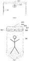
- FIG. 7 is an application schematic diagram of the human body security check device according to exemplary embodiment 3 of the present disclosure.
- a power value capable of realizing the minimum radiation hazard can be found within the power range allowing the image to be clear, and the power value is taken as the optimal power value radiated to a detected target (hereinafter referred to as target power value). If the power value radiated to the detected target can be maintained at the target power value regardless of the change of the ambient humidity (i.e., the power radiated to the detected target is kept at a constant value), radiation hazard can be reduced as much as possible while ensuring the definition of the image.
- the power of a signal attenuation part caused by the influence of the ambient humidity on the millimeter wave signal is compensated.
- the compensation is correspondingly low, and when the humidity is high, the compensation is correspondingly high.
- an adjustable power attenuator is arranged in the millimeter wave signal transmitting link of the millimeter wave transceiver in the exemplary embodiments of the disclosure; when low compensation is needed, the power attenuation value of the adjustable power attenuator is controlled to be large, and when high compensation is needed, the power attenuation value of the adjustable power attenuator is controlled to be small.
- the power attenuation value of the adjustable power attenuator and the power attenuation value caused to the millimeter wave signal by the ambient humidity are controlled to be a constant value.
- Exemplary embodiment 1 of the present disclosure provides a power adjustment method, which is applied in a human body security check device with a millimeter wave transceiver or other inspection devices with a millimeter wave transceiver.
- An adjustable power attenuator is provided in a millimeter wave signal transmitting link of the millimeter wave transceiver.
- FIG. 1 is a schematic diagram showing the implementation process of the power adjustment method according to exemplary embodiment 1 of the present disclosure. As shown in FIG. 1 , the power adjustment method according to exemplary embodiment 1 comprises:
- a current humidity value is obtained by detecting the ambient humidity around the millimeter wave transceiver using a preset humidity sensor.
- a humidity sensor can be arranged in the environment where the millimeter wave transceiver is located, and the ambient humidity around the millimeter wave transceiver can be detected by the humidity sensor to obtain a humidity detection result of the humidity sensor, namely the current humidity value.
- the plurality of humidity sensors are installed at different positions in a detection area of the human body security check device/inspection device respectively, and the average value of the humidity values detected by the plurality of humidity sensors can be calculated, and the calculated average value is taken as the current humidity value.
- a target power attenuation value of the adjustable power attenuator is determined according to the current humidity value, wherein the sum of the target power attenuation value and a power attenuation value caused to a millimeter wave signal by the ambient humidity is a constant value.
- the total power attenuation value is equal to the difference between the maximum transmission power of the millimeter wave transceiver and the above-mentioned target power value, which is a constant value, and the total power attenuation value can be preset, wherein the maximum transmission power value refers to the transmission power of the millimeter wave transceiver when the power attenuation value of the adjustable power attenuator is zero.
- the target power attenuation value can also be determined by looking up a table.
- the step of determining the target power attenuation value of the adjustable power attenuator according to the current humidity value may comprise: according to the current humidity and the corresponding relations between the current humidity value as well as a preset humidity value and the power attenuation value of the adjustable power attenuator, searching for the target power attenuation value corresponding to the current humidity value.
- the corresponding relation between the humidity value and the power attenuation value of the adjustable power attenuator is established in advance, and after obtaining the current humidity value, the target power attenuation value corresponding to the current humidity value needs to be searched for from the corresponding relation.
- the adjustable power attenuator is controlled to adjust its power attenuation value to be consistent with the target power attenuation value.
- an adjustment instruction carrying the target power attenuation value can be sent to the adjustable power attenuator, and after receiving the adjustment instruction, the adjustable power attenuator adjusts its own power attenuation value to be consistent with the target power attenuation value.
- the current humidity value is obtained by detecting the ambient humidity around the millimeter wave transceiver using the preset humidity sensor; the target power attenuation value of the adjustable power attenuator is determined according to the current humidity value, wherein the sum of the target power attenuation value and the power attenuation value caused to the millimeter wave signal by the ambient humidity is a constant value; and the adjustable power attenuator is controlled to adjust its power attenuation value to be consistent with the target power attenuation value; in this way, the power attenuation value of the adjustable power attenuator is determined based on the current humidity value, and the power attenuation value caused to the millimeter wave signal by the ambient humidity is compensated based on the power attenuation value of the adjustable power attenuator, so that the power radiated to a detected target can be kept constant at a power level which ensures the definition of an image and the minimum radiation hazard, that is, the power attenuation value of the adjustable
- exemplary embodiment 2 of the present disclosure provides a power adjustment apparatus, which is applied in a human body security check device or an inspection device provided with a millimeter wave transceiver.
- FIG. 2 is a structure diagram of the power adjustment apparatus according to exemplary embodiment 2 of the present disclosure.
- the power adjustment apparatus in the present embodiment comprises a humidity sensor 201 , a power controller 202 and an adjustable power attenuator 203 , the power controller 202 is connected to the humidity sensor 201 and the adjustable power attenuator 203 , and the adjustable power attenuator 203 is provided in a millimeter wave signal transmitting link of the millimeter wave transceiver.
- the humidity sensor 201 is used for detecting the ambient humidity around the millimeter wave transceiver to obtain a current humidity value
- the power controller 202 is used for determining a target power attenuation value of the adjustable power attenuator according to the current humidity value, and controlling the adjustable power attenuator 203 to adjust its power attenuation value to be consistent with the target power attenuation value, wherein the sum of the target power attenuation value and a power attenuation value caused to a millimeter wave signal by the ambient humidity is a constant value.
- FIG. 3 is a structure diagram of the human body security check device according to exemplary embodiment 3 of the present disclosure.
- the human body security check device in the present embodiment comprises a power adjustment apparatus 301 and a millimeter wave transceiver 302
- the power adjustment apparatus 301 comprises a humidity sensor 3011 , a power controller 3012 and an adjustable power attenuator 3013
- the power controller 3012 is connected to the humidity sensor 3011 and the adjustable power attenuator 3013
- the adjustable power attenuator 3013 is provided in a millimeter wave signal transmitting link of the millimeter wave transceiver 302 .
- the humidity sensor 3011 is used for detecting the ambient humidity around the millimeter wave transceiver to obtain a current humidity value
- the power controller 3012 is used for determining a target power attenuation value of the adjustable power attenuator 3013 according to the current humidity value, and controlling the adjustable power attenuator 3013 to adjust its power attenuation value to be consistent with the target power attenuation value, wherein the sum of the target power attenuation value and a power attenuation value caused to a millimeter wave signal by the ambient humidity is a constant value.
- the millimeter wave transceiver 302 may comprise a first signal source 401 , a second signal source 402 , a first directional coupler 403 , a second directional coupler 404 , a first power amplifier 405 , a second power amplifier 406 , a third power amplifier 407 , a first frequency mixer 408 , a second frequency mixer 409 , a third frequency mixer 410 , a first frequency doubler 411 , a second frequency doubler 412 , a third frequency doubler 413 , a low noise amplifier 414 , a transmitting antenna 415 and a receiving antenna 416 ;
- the first power amplifier 405 , the adjustable power attenuator 2013 , the first frequency doubler 411 and the transmitting antenna 415 are sequentially connected;
- an input end of the first directional coupler 403 is connected to an output end of the first signal source 401 , a straight-through end of the first directional coupler 403 is connected to an input end of the first power amplifier 405 , and a coupling end of the first directional coupler 403 is connected to a radio frequency end of the first frequency mixer 408 ;
- an intermediate frequency end of the first frequency mixer 408 is connected to a straight-through end of the second directional coupler 404 , an input end of the second directional coupler 404 is connected to an output end of the second signal source 402 , a local oscillator end of the first frequency mixer 408 is connected to an input end of the second power amplifier 406 , an output end of the second power amplifier 406 is connected to an input end of the second frequency doubler 412 , an output end of the second frequency doubler 412 is connected to a local oscillator end of the second frequency mixer 409 , and a radio frequency end of the second frequency mixer 409 is connected to the receiving antenna; and
- a coupling end of the second directional coupler 404 is connected to an input end of the third power amplifier 407 , an output end of the third power amplifier 407 is connected to an input end of the third frequency doubler 413 , an output end of the third frequency doubler 413 is connected to a local oscillation end of the third frequency mixer 410 , a radio frequency end of the third frequency mixer 410 is connected to an intermediate frequency end of the second frequency mixer 409 , and an intermediate frequency end of the third frequency mixer 410 is connected to the low noise amplifier 414 .
- the first signal source 401 may be a signal source with a working frequency of 17.5-22.5 GHz
- the second signal source 402 may be a voltage-controlled oscillator with a working frequency of 50 MHz.
- the first directional coupler 403 is a three-port device, and the straight-through end thereof is input to the first power amplifier 405 ; after passing through the adjustable power attenuator 3013 , the power of the present link (millimeter wave signal transmitting link) reaches the safe input power range of the first frequency doubler 411 ; and after passing through the first frequency doubler 411 , the input power of the present link is multiplied to 35-45 GHz, and finally radiated to a detected target by the transmitting antenna 415 .
- the first frequency mixer 308 is also a three-port device, the intermediate frequency end thereof is connected to the straight-through end of the second directional coupler 404 to input an intermediate frequency signal of 50 MHz, the radio frequency end thereof is connected to the coupling end of the first directional coupler 303 to input a signal of 17.5-22.5 GHz, and the local oscillator end thereof outputs a difference frequency signal of the radio frequency signal (signal of 17.5-22.5 GHz) and the intermediate frequency signal (intermediate frequency signal of 50 MHz) and then inputs the difference frequency signal to the second power amplifier 406 , so that the signal power thereof is amplified to be within the safe working range of the second frequency doubler 412 .
- the third frequency mixer 410 outputs a downconverted signal with target information, the local oscillator end thereof is input a 100 MHz continuous wave signal, which is emitted by the second signal source through the coupling end of the second directional coupler 404 , the third power amplifier 407 , and the third frequency doubler 413 , and the intermediate frequency end thereof outputs a second downconverted signal with the target information.
- the low noise amplifier 414 amplifies the weak intermediate frequency signal which is generated by executing downconversion twice to improve the signal-to-noise ratio and detection sensitivity of the output signal.
- FIG. 4 shows a preferred structure of the millimeter wave transceiver 302 , and the millimeter wave transceiver may include only one part of the components shown in FIG. 4 according to requirements.
- a single-pole multi-throw switch 417 may be connected between the second signal source 402 and the second directional coupler 404 , so that switching among a plurality of millimeter wave transceivers 302 can be realized through one single-pole multi-throw switch 417 .
- the single-pole multi-throw switch 417 may be a single-pole eight-throw switch, so that switching among the eight millimeter wave transceivers 302 can be realized through one single-pole eight-throw switch.
- the plurality of millimeter wave transceivers 302 are controlled by a two-layer single-pole multiple-throw switch.
- the two-layer single-pole multi-throw switch is connected between the second signal source 402 and the second directional coupler 402 .
- the two-layer single-pole multi-throw switch can realize n 2 switch combinations, wherein n represents the throw number.
- the two-layer single-pole eight-throw switch has a throw number of 8, so that 64 switch combinations can be realized; therefore, switching between 64 millimeter wave transceivers 202 can be realized through the two-layer single-pole eight-throw switch, and the 64 millimeter wave transceivers do not work at the same time, but are controlled by the two-layer single-pole eight-throw switch to transmit and receive one by one.
- the human body security check device of the disclosure may further comprise a scanning device 303 .
- the scanning device 303 comprises a cantilever 3031 and a driving motor 3032 .
- the millimeter wave transceiver 302 is hung at an end of the cantilever 3031 , and the driving motor drives the cantilever to move in a circle so as to detect the front and back of the detected target.
- the plurality of millimeter wave transceivers 302 may be vertically arranged in two columns, and the two columns of millimeter wave transceivers 302 are hung at two ends of the cantilever 3031 respectively.
- the human body security check device of the disclosure may further comprise a data acquiring and processing unit 304 and an image display unit 305 .
- the data acquiring and processing unit 304 is connected to the millimeter wave transceiver 302 and the image display unit 305 , and the data acquiring and processing unit 304 is used for acquiring an echo signal from the millimeter wave transceiver 302 , performing Fourier transform of geometric characteristics on the acquired echo signal, simplifying and deforming the resulting data of Fourier transform, then performing inverse Fourier transform to obtain a target three-dimensional image, and transmitting the target three-dimensional image to the image display unit for display.
- Fourier transform of geometric characteristics, simplification and deformation of the result data of Fourier transform, and inverse Fourier transform can all be implemented by existing methods, which will not be described in detail here.
- the detected target 306 e.g., a person
- the driving motor 3032 and the cantilever 3041 can be arranged on the top of the human body security check device, and a row of millimeter wave transceivers 3021 and 3022 are hung at two ends of 3041 respectively.
- the driving motor 3032 drives the millimeter wave transceivers 3021 and 3022 to move in a circle to scan the front and back of the detected target ( 306 ).
- the millimeter wave transceivers 3021 and 3022 radiate the millimeter wave signal to the detected target 306 , the detected target 306 returns electromagnetic waves (called echo signal) with target information, and the echo signal is processed by the data acquiring and processing unit 304 to generate a three-dimensional image of the detected target 306 for display on the image display unit 305 .
Abstract
Description
Claims (8)
Applications Claiming Priority (3)
| Application Number | Priority Date | Filing Date | Title |
|---|---|---|---|
| CN201610808565.1 | 2016-09-07 | ||
| CN201610808565.1A CN106291740B (en) | 2016-09-07 | 2016-09-07 | Power regulating method, device and human body safety check equipment |
| PCT/CN2017/100720 WO2018045964A1 (en) | 2016-09-07 | 2017-09-06 | Power adjustment method and apparatus, and human body security check device |
Publications (2)
| Publication Number | Publication Date |
|---|---|
| US20190260121A1 US20190260121A1 (en) | 2019-08-22 |
| US11283167B2 true US11283167B2 (en) | 2022-03-22 |
Family
ID=57711013
Family Applications (1)
| Application Number | Title | Priority Date | Filing Date |
|---|---|---|---|
| US16/331,113 Active 2039-02-22 US11283167B2 (en) | 2016-09-07 | 2017-09-06 | Power adjustment method and apparatus, and human body security check device |
Country Status (4)
| Country | Link |
|---|---|
| US (1) | US11283167B2 (en) |
| EP (1) | EP3511745B1 (en) |
| CN (1) | CN106291740B (en) |
| WO (1) | WO2018045964A1 (en) |
Families Citing this family (6)
| Publication number | Priority date | Publication date | Assignee | Title |
|---|---|---|---|---|
| CN106291740B (en) | 2016-09-07 | 2017-09-15 | 华讯方舟科技有限公司 | Power regulating method, device and human body safety check equipment |
| CN210155349U (en) * | 2018-03-09 | 2020-03-17 | 同方威视技术股份有限公司 | Extensible millimeter wave security inspection system and scanning unit |
| CN108983211B (en) * | 2018-07-02 | 2022-08-09 | Oppo广东移动通信有限公司 | Proximity sensor, method of controlling the same, electronic device, and computer-readable storage medium |
| CN110672639A (en) * | 2019-08-19 | 2020-01-10 | 珠海格力电器股份有限公司 | Humidity detection method and device based on millimeter waves, humidity adjustment equipment and air conditioner |
| CN113514903B (en) * | 2021-06-29 | 2023-07-25 | 昆山亚伯兰软件科技有限公司 | Infrared correlation tube power compensation method and system |
| CN114917482B (en) * | 2022-06-24 | 2023-12-01 | 北京中成康富科技股份有限公司 | Millimeter wave therapeutic apparatus for prostate |
Citations (20)
| Publication number | Priority date | Publication date | Assignee | Title |
|---|---|---|---|---|
| WO2008054865A2 (en) | 2006-04-26 | 2008-05-08 | L-3 Communications Security And Detection Systems, Inc. | Multi-source surveillance systems |
| US20100214150A1 (en) | 2003-08-12 | 2010-08-26 | Trex Enterprises Corp. | Millimeter wave imaging system with frequency scanning antenna |
| CN101977022A (en) | 2010-09-03 | 2011-02-16 | 中兴通讯股份有限公司 | Complementary-multiplicative power compensation method, device and communication equipment |
| CN102426361A (en) | 2011-10-30 | 2012-04-25 | 北京无线电计量测试研究所 | Human body security inspection system used for millimeter wave active three-dimensional holographic imaging |
| CN102759753A (en) | 2011-04-29 | 2012-10-31 | 同方威视技术股份有限公司 | Method and device for detecting hidden dangerous article |
| CN104062620A (en) | 2014-07-16 | 2014-09-24 | 中国科学院上海微系统与信息技术研究所 | Power calibration test system and power calibration measurement method |
| CN204154908U (en) | 2014-08-28 | 2015-02-11 | 北京环境特性研究所 | Terahertz rays safety detection apparatus |
| CN204228978U (en) | 2014-11-07 | 2015-03-25 | 深圳市一体投资控股集团有限公司 | A kind of three-dimensional image forming apparatus |
| CN104833969A (en) | 2015-05-04 | 2015-08-12 | 安徽美意希提光电科技有限公司 | Active millimeter wave contraband detecting instrument |
| CN105224002A (en) | 2014-06-30 | 2016-01-06 | 展讯通信(上海)有限公司 | Radio system temperature compensation, device and mobile terminal |
| CN105372647A (en) | 2014-08-27 | 2016-03-02 | 北京顶亮科技有限公司 | Millimeter wave range finder system and method based on active phased array transceiver component |
| CN105372665A (en) | 2014-08-27 | 2016-03-02 | 北京顶亮科技有限公司 | Infrared millimeter-wave ranging device and method |
| CN105510911A (en) | 2015-12-25 | 2016-04-20 | 深圳市太赫兹科技创新研究院 | Linear frequency modulation-based multi-human body safety inspection apparatus and method |
| CN105759269A (en) | 2016-04-25 | 2016-07-13 | 深圳市无牙太赫兹科技有限公司 | Three-dimensional holographic imaging safety inspection system and method thereof |
| CN105938206A (en) | 2016-07-06 | 2016-09-14 | 华讯方舟科技有限公司 | Millimeter wave security check instrument debugging system and millimeter wave security check instrument debugging method |
| CN106094734A (en) | 2016-07-21 | 2016-11-09 | 华讯方舟科技有限公司 | Safety check instrument kinetic control system |
| CN106291740A (en) | 2016-09-07 | 2017-01-04 | 华讯方舟科技有限公司 | Power regulating method, device and human body safety check equipment |
| CN206020692U (en) | 2016-09-07 | 2017-03-15 | 华讯方舟科技有限公司 | PCU Power Conditioning Unit and human body safety check equipment |
| CN106680814A (en) | 2016-12-09 | 2017-05-17 | 华讯方舟科技有限公司 | Rotary scanning 3D imaging system |
| CN206339649U (en) | 2016-12-09 | 2017-07-18 | 华讯方舟科技有限公司 | Rotation sweep 3-D imaging system |
-
2016
- 2016-09-07 CN CN201610808565.1A patent/CN106291740B/en active Active
-
2017
- 2017-09-06 EP EP17848137.0A patent/EP3511745B1/en active Active
- 2017-09-06 US US16/331,113 patent/US11283167B2/en active Active
- 2017-09-06 WO PCT/CN2017/100720 patent/WO2018045964A1/en unknown
Patent Citations (22)
| Publication number | Priority date | Publication date | Assignee | Title |
|---|---|---|---|---|
| US20100214150A1 (en) | 2003-08-12 | 2010-08-26 | Trex Enterprises Corp. | Millimeter wave imaging system with frequency scanning antenna |
| US7948428B2 (en) | 2003-08-12 | 2011-05-24 | Trex Enterprises Corp. | Millimeter wave imaging system with frequency scanning antenna |
| WO2008054865A2 (en) | 2006-04-26 | 2008-05-08 | L-3 Communications Security And Detection Systems, Inc. | Multi-source surveillance systems |
| CN101977022A (en) | 2010-09-03 | 2011-02-16 | 中兴通讯股份有限公司 | Complementary-multiplicative power compensation method, device and communication equipment |
| CN102759753A (en) | 2011-04-29 | 2012-10-31 | 同方威视技术股份有限公司 | Method and device for detecting hidden dangerous article |
| CN102426361A (en) | 2011-10-30 | 2012-04-25 | 北京无线电计量测试研究所 | Human body security inspection system used for millimeter wave active three-dimensional holographic imaging |
| CN105224002A (en) | 2014-06-30 | 2016-01-06 | 展讯通信(上海)有限公司 | Radio system temperature compensation, device and mobile terminal |
| CN104062620A (en) | 2014-07-16 | 2014-09-24 | 中国科学院上海微系统与信息技术研究所 | Power calibration test system and power calibration measurement method |
| CN105372647A (en) | 2014-08-27 | 2016-03-02 | 北京顶亮科技有限公司 | Millimeter wave range finder system and method based on active phased array transceiver component |
| CN105372665A (en) | 2014-08-27 | 2016-03-02 | 北京顶亮科技有限公司 | Infrared millimeter-wave ranging device and method |
| CN204154908U (en) | 2014-08-28 | 2015-02-11 | 北京环境特性研究所 | Terahertz rays safety detection apparatus |
| CN204228978U (en) | 2014-11-07 | 2015-03-25 | 深圳市一体投资控股集团有限公司 | A kind of three-dimensional image forming apparatus |
| CN104833969A (en) | 2015-05-04 | 2015-08-12 | 安徽美意希提光电科技有限公司 | Active millimeter wave contraband detecting instrument |
| CN105510911A (en) | 2015-12-25 | 2016-04-20 | 深圳市太赫兹科技创新研究院 | Linear frequency modulation-based multi-human body safety inspection apparatus and method |
| US20190025421A1 (en) * | 2015-12-25 | 2019-01-24 | Shenzhen Cct Thz Technology Co., Ltd. | Apparatus and method for security check of multiple human bodies based on linear frequency modulation |
| CN105759269A (en) | 2016-04-25 | 2016-07-13 | 深圳市无牙太赫兹科技有限公司 | Three-dimensional holographic imaging safety inspection system and method thereof |
| CN105938206A (en) | 2016-07-06 | 2016-09-14 | 华讯方舟科技有限公司 | Millimeter wave security check instrument debugging system and millimeter wave security check instrument debugging method |
| CN106094734A (en) | 2016-07-21 | 2016-11-09 | 华讯方舟科技有限公司 | Safety check instrument kinetic control system |
| CN106291740A (en) | 2016-09-07 | 2017-01-04 | 华讯方舟科技有限公司 | Power regulating method, device and human body safety check equipment |
| CN206020692U (en) | 2016-09-07 | 2017-03-15 | 华讯方舟科技有限公司 | PCU Power Conditioning Unit and human body safety check equipment |
| CN106680814A (en) | 2016-12-09 | 2017-05-17 | 华讯方舟科技有限公司 | Rotary scanning 3D imaging system |
| CN206339649U (en) | 2016-12-09 | 2017-07-18 | 华讯方舟科技有限公司 | Rotation sweep 3-D imaging system |
Non-Patent Citations (4)
| Title |
|---|
| CN105224002 translation (Year: 2016). * |
| Joan Figueras Tugas, "Privacy and Body Scanners at EU Airports", Nov. 1, 2013 (Nov. 1, 2013), XP055681167, Retrieved from the Internet: URL:https://www.researchgate.net/publication/317369679_Privacy_and_Body_Scanners_at_EU_Airports/, [retrieved on Mar. 31, 2020]. |
| Marcus et al., "Millimeter Wave Propagation; Spectrum Management Implications", IEEE Microwave Magazine, IEEESERVICE Center, Piscataway, NJ, US, vol. 6, No. 2, 1 Jun. 1, 2005, pp. 54-62, XP011137132, ISSN: 1527-3342, DOI: 10.1109/MMW.2005.1491267. |
| MARCUS M., PATTAN B.: "Millimeter wave propagation; spectrum management implications", IEEE MICROWAVE MAGAZINE., IEEESERVICE CENTER, PISCATAWAY, NJ., US, vol. 6, no. 2, 1 June 2005 (2005-06-01), US , pages 54 - 62, XP011137132, ISSN: 1527-3342, DOI: 10.1109/MMW.2005.1491267 |
Also Published As
| Publication number | Publication date |
|---|---|
| WO2018045964A1 (en) | 2018-03-15 |
| EP3511745A4 (en) | 2020-05-06 |
| EP3511745A1 (en) | 2019-07-17 |
| EP3511745B1 (en) | 2023-01-11 |
| US20190260121A1 (en) | 2019-08-22 |
| CN106291740A (en) | 2017-01-04 |
| CN106291740B (en) | 2017-09-15 |
Similar Documents
| Publication | Publication Date | Title |
|---|---|---|
| US11283167B2 (en) | Power adjustment method and apparatus, and human body security check device | |
| US11313963B2 (en) | Millimeter wave holographic three-dimensional imaging detection system and method | |
| WO2017107283A1 (en) | Apparatus and method for security check of multiple human bodies based on linear frequency modulation | |
| US20210088649A1 (en) | Millimeter-wave real-time imaging based safety inspection system and safety inspection method | |
| US11125906B2 (en) | Millimeter wave imaging-based omni-directional security detection system | |
| JP2006267102A (en) | System and method for inspecting transportable items using microwave imaging | |
| EP1813963A2 (en) | Target detection apparatus and system | |
| US9013348B2 (en) | Radiometric imaging device and corresponding method | |
| US20050099331A1 (en) | Concealed object detection | |
| CN205608180U (en) | Three -dimensional holographic imaging's security inspection system | |
| CN108152821A (en) | A kind of active MMW imaging safety detecting system and safety detection method | |
| Kapilevich et al. | Detecting hidden objects on human body using active millimeter wave sensor | |
| CN105974486A (en) | Equipment of detecting articles in shoes | |
| KR102152133B1 (en) | Millimeter wave radiometer system | |
| Nemati et al. | Experimental validation of a novel multistatic toroidal reflector nearfield imaging system for concealed threat detection | |
| Mencia-Oliva et al. | 100-GHz FMCW radar front-end for ISAR and 3D imaging | |
| CN205450266U (en) | Human security installations of many people based on linear FM | |
| KR20140066875A (en) | Terahertz real-time detection and imaging system for nondestructive testing based on high power terahertz radiation source | |
| CN206020692U (en) | PCU Power Conditioning Unit and human body safety check equipment | |
| Monnai | Terahertz Radar Based on Leaky-Wave Coherence Tomography | |
| RU2522853C1 (en) | Method and apparatus for detecting and identifying objects hidden under clothes on human body | |
| Hozhabri et al. | Experimental comparison study of UWB technologies for static human detection | |
| Liang et al. | Millimeter-wave near-field holographic imaging based on VNA | |
| RU164965U1 (en) | THERAHZ RADAR | |
| Paulter et al. | Design of an active mm-wave concealed-object imaging system |
Legal Events
| Date | Code | Title | Description |
|---|---|---|---|
| FEPP | Fee payment procedure |
Free format text: ENTITY STATUS SET TO UNDISCOUNTED (ORIGINAL EVENT CODE: BIG.); ENTITY STATUS OF PATENT OWNER: SMALL ENTITY |
|
| FEPP | Fee payment procedure |
Free format text: ENTITY STATUS SET TO SMALL (ORIGINAL EVENT CODE: SMAL); ENTITY STATUS OF PATENT OWNER: SMALL ENTITY |
|
| AS | Assignment |
Owner name: SHENZHEN INSTITUTE OF TERAHERTZ TECHNOLOGY AND INNOVATION, CHINA Free format text: ASSIGNMENT OF ASSIGNORS INTEREST;ASSIGNORS:QI, CHUNCHAO;ZHAO, SHUKAI;CHEN, HANJIANG;AND OTHERS;REEL/FRAME:048696/0757 Effective date: 20190306 Owner name: CHINA COMMUNICATION TECHNOLOGY CO., LTD., CHINA Free format text: ASSIGNMENT OF ASSIGNORS INTEREST;ASSIGNORS:QI, CHUNCHAO;ZHAO, SHUKAI;CHEN, HANJIANG;AND OTHERS;REEL/FRAME:048696/0757 Effective date: 20190306 Owner name: SHENZHEN INSTITUTE OF TERAHERTZ TECHNOLOGY AND INN Free format text: ASSIGNMENT OF ASSIGNORS INTEREST;ASSIGNORS:QI, CHUNCHAO;ZHAO, SHUKAI;CHEN, HANJIANG;AND OTHERS;REEL/FRAME:048696/0757 Effective date: 20190306 |
|
| STPP | Information on status: patent application and granting procedure in general |
Free format text: DOCKETED NEW CASE - READY FOR EXAMINATION |
|
| STPP | Information on status: patent application and granting procedure in general |
Free format text: NON FINAL ACTION MAILED |
|
| STPP | Information on status: patent application and granting procedure in general |
Free format text: RESPONSE TO NON-FINAL OFFICE ACTION ENTERED AND FORWARDED TO EXAMINER |
|
| STCF | Information on status: patent grant |
Free format text: PATENTED CASE |