US11268257B1 - Swivel bucket - Google Patents
Swivel bucket Download PDFInfo
- Publication number
- US11268257B1 US11268257B1 US17/090,503 US202017090503A US11268257B1 US 11268257 B1 US11268257 B1 US 11268257B1 US 202017090503 A US202017090503 A US 202017090503A US 11268257 B1 US11268257 B1 US 11268257B1
- Authority
- US
- United States
- Prior art keywords
- bucket
- floor
- axis
- pivot plate
- attached
- Prior art date
- Legal status (The legal status is an assumption and is not a legal conclusion. Google has not performed a legal analysis and makes no representation as to the accuracy of the status listed.)
- Active
Links
- 238000000034 method Methods 0.000 description 3
- 210000005069 ears Anatomy 0.000 description 1
- 238000012986 modification Methods 0.000 description 1
- 230000004048 modification Effects 0.000 description 1
- 238000007790 scraping Methods 0.000 description 1
Images


Classifications
-
- E—FIXED CONSTRUCTIONS
- E02—HYDRAULIC ENGINEERING; FOUNDATIONS; SOIL SHIFTING
- E02F—DREDGING; SOIL-SHIFTING
- E02F3/00—Dredgers; Soil-shifting machines
- E02F3/04—Dredgers; Soil-shifting machines mechanically-driven
- E02F3/28—Dredgers; Soil-shifting machines mechanically-driven with digging tools mounted on a dipper- or bucket-arm, i.e. there is either one arm or a pair of arms, e.g. dippers, buckets
- E02F3/34—Dredgers; Soil-shifting machines mechanically-driven with digging tools mounted on a dipper- or bucket-arm, i.e. there is either one arm or a pair of arms, e.g. dippers, buckets with bucket-arms, i.e. a pair of arms, e.g. manufacturing processes, form, geometry, material of bucket-arms directly pivoted on the frames of tractors or self-propelled machines
- E02F3/3417—Buckets emptying by tilting
-
- E—FIXED CONSTRUCTIONS
- E02—HYDRAULIC ENGINEERING; FOUNDATIONS; SOIL SHIFTING
- E02F—DREDGING; SOIL-SHIFTING
- E02F3/00—Dredgers; Soil-shifting machines
- E02F3/04—Dredgers; Soil-shifting machines mechanically-driven
- E02F3/28—Dredgers; Soil-shifting machines mechanically-driven with digging tools mounted on a dipper- or bucket-arm, i.e. there is either one arm or a pair of arms, e.g. dippers, buckets
- E02F3/34—Dredgers; Soil-shifting machines mechanically-driven with digging tools mounted on a dipper- or bucket-arm, i.e. there is either one arm or a pair of arms, e.g. dippers, buckets with bucket-arms, i.e. a pair of arms, e.g. manufacturing processes, form, geometry, material of bucket-arms directly pivoted on the frames of tractors or self-propelled machines
- E02F3/345—Buckets emptying side-ways
-
- E—FIXED CONSTRUCTIONS
- E02—HYDRAULIC ENGINEERING; FOUNDATIONS; SOIL SHIFTING
- E02F—DREDGING; SOIL-SHIFTING
- E02F3/00—Dredgers; Soil-shifting machines
- E02F3/04—Dredgers; Soil-shifting machines mechanically-driven
- E02F3/28—Dredgers; Soil-shifting machines mechanically-driven with digging tools mounted on a dipper- or bucket-arm, i.e. there is either one arm or a pair of arms, e.g. dippers, buckets
- E02F3/36—Component parts
- E02F3/3604—Devices to connect tools to arms, booms or the like
- E02F3/3677—Devices to connect tools to arms, booms or the like allowing movement, e.g. rotation or translation, of the tool around or along another axis as the movement implied by the boom or arms, e.g. for tilting buckets
-
- E—FIXED CONSTRUCTIONS
- E02—HYDRAULIC ENGINEERING; FOUNDATIONS; SOIL SHIFTING
- E02F—DREDGING; SOIL-SHIFTING
- E02F3/00—Dredgers; Soil-shifting machines
- E02F3/04—Dredgers; Soil-shifting machines mechanically-driven
- E02F3/28—Dredgers; Soil-shifting machines mechanically-driven with digging tools mounted on a dipper- or bucket-arm, i.e. there is either one arm or a pair of arms, e.g. dippers, buckets
- E02F3/36—Component parts
- E02F3/40—Dippers; Buckets ; Grab devices, e.g. manufacturing processes for buckets, form, geometry or material of buckets
-
- E—FIXED CONSTRUCTIONS
- E02—HYDRAULIC ENGINEERING; FOUNDATIONS; SOIL SHIFTING
- E02F—DREDGING; SOIL-SHIFTING
- E02F3/00—Dredgers; Soil-shifting machines
- E02F3/04—Dredgers; Soil-shifting machines mechanically-driven
- E02F3/64—Buckets cars, i.e. having scraper bowls
- E02F3/65—Component parts, e.g. drives, control devices
- E02F3/651—Hydraulic or pneumatic drives; Electric or electro-mechanical control devices
-
- E—FIXED CONSTRUCTIONS
- E02—HYDRAULIC ENGINEERING; FOUNDATIONS; SOIL SHIFTING
- E02F—DREDGING; SOIL-SHIFTING
- E02F3/00—Dredgers; Soil-shifting machines
- E02F3/04—Dredgers; Soil-shifting machines mechanically-driven
- E02F3/28—Dredgers; Soil-shifting machines mechanically-driven with digging tools mounted on a dipper- or bucket-arm, i.e. there is either one arm or a pair of arms, e.g. dippers, buckets
- E02F3/36—Component parts
- E02F3/40—Dippers; Buckets ; Grab devices, e.g. manufacturing processes for buckets, form, geometry or material of buckets
- E02F3/407—Dippers; Buckets ; Grab devices, e.g. manufacturing processes for buckets, form, geometry or material of buckets with ejecting or other unloading device
Definitions
- the present disclosure is directed generally to a pivoting bucket. Specifically, a bucket which can be attached to a machine and rotated along multiple axes.
- Buckets are commonly used by people to move large amounts of material or heavy items. These buckets are often attached to machines such as skid steers, mini skid steers, tractors, or others. Some problems that conventional buckets have are they are not capable of moving in small spaces, they are not easily maneuverable, and they cannot be dumped into tall containers.
- Conventional buckets can only move on the y-axis and the z-axis, meaning that they can only be moved up and down and be dumped. Therefore, when a user wants to be able to load the bucket from the left or the right or wants to dump the bucket to the left or the right the user has to move the entire machine to place the bucket into a different location. Most conventional buckets can only be dumped into container that are the height the machine extends, this is a problem for dumping into tall containers or trucks. While some buckets are capable of high dumping, they are not also capable of rotating.
- the present disclosure is directed to a swivel bucket.
- the swivel bucket can be rotated along multiple axes, including the x-axis, y-axis, and the z-axis.
- the swivel bucket can be attached to a mini skid steer, regular skid steer, tractor, or another suitable device (as should be understood by a person of skill in the art in conjunction with a review of this disclosure).
- the swivel bucket can high dump, meaning that it can be dumped from a higher elevation than a regular or low dumping bucket. This allows for the contents of the bucket to be emptied into the back or trucks or taller containers.
- high dump is achieved by the attachment device being attached to the lower portion of the bottom of the bucket as opposed to the top of the bottom of the bucket.
- the bucket is capable of moving on the x-axis, the y-axis, and the z-axis. This is better for collecting items and moving into smaller spaces.
- the rotation of the bucket allows the swivel bucket to move into smaller spaces, to be dumped at different spots, and to be loaded in varying ways all without the user moving the device in which the bucket is attached to.
- Typical buckets require movement of the entire device to move the position of the bucket.
- a bucket assembly for mounting to a machine, comprising a bucket defined by a floor having an inwardly and outwardly facing surfaces, a rear wall extending upwardly from the floor, opposing side walls each extending upwardly from the floor and connected along a rear edge to the rear wall, and an open front defined by the space between front edges of the opposing side walls, wherein the spacing between the front edges of the side walls is greater than the spacing between the rear edges of the side walls, and the floor grades downwardly from the rear wall towards the open front; a mounting assembly for mounting the bucket to the machine, comprising: a mounting plate adapted for secure attachment to the machine; a pivot plate extending in a plane and pivotally attached to the outwardly facing surface of the floor; a dumping mechanism extending between the outwardly facing surface of the floor and the pivot plate that is actuable to pivotally move the bucket about a horizontal axis between dumping and loading positions; a swivel mechanism attached to the pivot plate that is actuable to rotate the bucket about
- the swivel mechanism comprises a piston and cylinder attached at a fixed end to the mounting plate and at an extendible/retractible end to the pivot plate, wherein extension or retraction of the cylinder causes rotation of the bucket about the longitudinal bearing axis.
- the dumping mechanism comprises a piston and cylinder attached at a fixed end to the pivot plate and to an extendible/retractible end to the outwardly facing surface of the floor by a pin that extends along a pivot axis, wherein extension of retraction of the cylinder causes pivoting or the bucket about the pivot axis.
- FIG. 1 is a front view of an example of a swivel bucket, in accordance with an embodiment.
- FIG. 2 is a back view of an example of a swivel bucket, in accordance with an embodiment.
- FIG. 3 is a bottom view of an example of a swivel bucket, in accordance with an embodiment.
- FIG. 4 is a bottom view of an example of a swivel bucket, in accordance with an embodiment.
- FIG. 5 is a top view of an example of a swivel bucket, in accordance with an embodiment.
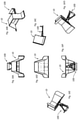
- FIG. 6 is a perspective view of an example of a swivel bucket, in accordance with an embodiment.
- FIG. 7 is a perspective view of an example of a swivel bucket, in accordance with an embodiment.
- FIG. 8 is a perspective view of an example of a swivel bucket, in accordance with an embodiment.
- FIG. 9 is a side view of an example of a swivel bucket, in accordance with an embodiment.
- FIG. 10 is a side view of an example of a swivel bucket, in accordance with an embodiment.
- FIG. 11 is a perspective view of an example of a swivel bucket, in accordance with an embodiment.
- FIG. 12 is an enlarged bottom view of an example of a swivel bucket, in accordance with an embodiment.
- FIG. 13 is a perspective view of an example of a swivel bucket with arrows illustrating possible movement, in accordance with an embodiment.
- FIG. 14 is a perspective view of an example of a swivel bucket with arrows illustrating possible movement, in accordance with an embodiment.
- FIG. 15 is a perspective view of an example of a swivel bucket with arrows illustrating possible movement, in accordance with an embodiment.
- FIGS. 16A-16G are multiple elevation views of an example of a swivel bucket, in accordance with an embodiment.
- FIGS. 17A-17G are multiple elevation views of the mounting plate and rods of an example of the attachment device of a swivel bucket, in accordance with an embodiment.
- FIG. 18A-18E are multiple elevation views of the pivot plate and bracket of an example of an attachment device of a swivel bucket, in accordance with an embodiment.
- FIG. 19 is a labeled front view of an example of a swivel bucket, in accordance with an embodiment.
- FIG. 20 is a back view of an example of a swivel bucket, in accordance with an embodiment.
- FIG. 21 is a perspective view of a machine having a swivel bucket mounted thereto, in accordance with an embodiment.
- FIG. 22A-22F are multiple elevation views of notched plate, in accordance with an embodiment.
- FIG. 23 is a perspective view of a gear arrangement, in accordance with an embodiment.
- the present disclosure describes a swivel bucket capable of movement relative to the x-axis, y-axis, and z-axis.
- Bucket 10 adapted for mounting to a machine 12 such as a tractor, skid steer, and the like by means of an attachment assembly, designated generally by reference numeral 100 .
- Bucket 10 generally comprises a back wall 14 , a floor comprising three panels 16 , 18 and 20 , opposing side walls each of which comprises two panels 22 , 24 , and 26 , 28 , respectively, and an open front 30 .
- Side wall panels 22 and 26 each extend forward from back wall 14
- side wall panels 24 and 28 extend forward from panels 22 and 26 , respectively, and taper outwardly towards the open front 30 .
- open front 30 is of a greater width than is the back wall 14 .
- Floor panel 16 extends forward from the bottom of back wall 14
- middle floor panel 18 extends forward from panel 16
- forward floor panel 20 extends forward from middle panel 18 .
- Middle and forward floor panels 18 and 20 each slope downwardly, and the leading edge of forward panel 20 includes a scraping edge.
- Attachment assembly 100 comprises a mounting plate 102 that is adapted to securely attach to machine 12 in a conventional manner and a pivot plate 104 that attaches to the outwardly facing surface of floor panel 18 .
- Mounting plate 102 is attached to pivot plate 104 via a pair of diagonally extending braces 106 , 108 that extend from the outer edges of the mounting plate 102 diagonally inwardly to pivot plate 104 .
- Brace 106 includes a yoke (or ears) 110 to which one end of a piston/cylinder 112 is attached via a pin.
- Pivot plate 104 further includes an opening 116 formed therethrough and through which a bearing 118 is mounted; bearing 118 can absorb both thrust for when the bucket 10 is loaded, as well as permit rotation about the axis X-X that extends through opening 116 .
- Mounting assembly 100 further comprises a second piston/cylinder 120 that has its fixed end pined to pivot plate 104 and its extendible/retractable end pinned to the outwardly facing surface of floor plate 18 .
- Piston/cylinders 112 and 120 can be hydraulically driven, electrically driven solenoids, or any other form of extensible element known in the art.
- bucket 10 can be raised or lowered using the conventional lift arms on machine 12 , and can then be rotated about axis X-X through control of piston/cylinder 112 that can extend or retract and in so doing, rotate the bucket about axis X-X (i.e., about the bearing 118 ).
- the bucket 10 can then be pivoted about the axis Y-Y that extends through the pin that connects retractable/extendible arm of piston/cylinder 120 to the floor plate 18 .
- bucket 10 can also be lowered into engagement with the ground and/or raised to permit a high dumping of contents.
- That element can be replaced with a notched plate 200 (plate 200 has a series of notches 201 cut out in spaced intervals about its periphery) as shown in FIGS. 22A-22F .
- Notched plate 200 connects to pivot plate 104 and includes a pin 202 that can be moved into and out of engagement with any one of the notches formed around the perimeter of plate 200 .
- the plate 200 is semi-circular, but could form more or less of a circle as desired could permit rotation up to 360 degrees), but as shown permits rotation of up to 180 degrees.
- Pin 202 can be formed at the end of a rod 204 that can be manually or automatically moved towards and away from plate 200 to secure or release and permit the rotational positioning of bucket 10 .
- a gear 300 can be used in place of plate 200 , and a drive gear 302 can be engaged with gear 300 used to effect rotation of bucket 10 about the axis X-X.
Abstract
A bucket assembly for attachment to a machine, such as a skid steer or tractor, that includes a bucket and a mounting assembly that permits swiveling of the bucket about a vertical axis and pivoting of the bucket about a horizontal axis.
Description
This application claims priority to U.S. Provisional Patent Application Ser. No. 62/930,918, filed on Nov. 5, 2019, and entitled “Swivel Bucket,” the entire disclosure of which is incorporated herein by reference.
The present disclosure is directed generally to a pivoting bucket. Specifically, a bucket which can be attached to a machine and rotated along multiple axes.
Buckets are commonly used by people to move large amounts of material or heavy items. These buckets are often attached to machines such as skid steers, mini skid steers, tractors, or others. Some problems that conventional buckets have are they are not capable of moving in small spaces, they are not easily maneuverable, and they cannot be dumped into tall containers.
Conventional buckets can only move on the y-axis and the z-axis, meaning that they can only be moved up and down and be dumped. Therefore, when a user wants to be able to load the bucket from the left or the right or wants to dump the bucket to the left or the right the user has to move the entire machine to place the bucket into a different location. Most conventional buckets can only be dumped into container that are the height the machine extends, this is a problem for dumping into tall containers or trucks. While some buckets are capable of high dumping, they are not also capable of rotating.
Description of the Related Art Section Disclaimer: To the extent that specific patents/publications/products are discussed above in this Background Section or elsewhere in this Application, these discussions should not be taken as an admission that the discussed patents/publications/products are prior art for patent law purposes. For example, some or all of the discussed patents/publications/products may not be sufficiently early in time, may not reflect subject matter developed early enough in time and/or may not be sufficiently enabling so as to amount to prior art for patent law purposes. To the extent that specific patents/publications/products are discussed above in this Background Section and/or throughout the application, the descriptions/disclosures of which are all hereby incorporated by reference into this document in their respective entirety(ies).
The present disclosure is directed to a swivel bucket.
To solve the above-mentioned problems the swivel bucket can be rotated along multiple axes, including the x-axis, y-axis, and the z-axis. The swivel bucket can be attached to a mini skid steer, regular skid steer, tractor, or another suitable device (as should be understood by a person of skill in the art in conjunction with a review of this disclosure). The swivel bucket can high dump, meaning that it can be dumped from a higher elevation than a regular or low dumping bucket. This allows for the contents of the bucket to be emptied into the back or trucks or taller containers. In one example, high dump is achieved by the attachment device being attached to the lower portion of the bottom of the bucket as opposed to the top of the bottom of the bucket.
The bucket is capable of moving on the x-axis, the y-axis, and the z-axis. This is better for collecting items and moving into smaller spaces. The rotation of the bucket allows the swivel bucket to move into smaller spaces, to be dumped at different spots, and to be loaded in varying ways all without the user moving the device in which the bucket is attached to. Typical buckets require movement of the entire device to move the position of the bucket.
According to an aspect is a bucket assembly for mounting to a machine, comprising a bucket defined by a floor having an inwardly and outwardly facing surfaces, a rear wall extending upwardly from the floor, opposing side walls each extending upwardly from the floor and connected along a rear edge to the rear wall, and an open front defined by the space between front edges of the opposing side walls, wherein the spacing between the front edges of the side walls is greater than the spacing between the rear edges of the side walls, and the floor grades downwardly from the rear wall towards the open front; a mounting assembly for mounting the bucket to the machine, comprising: a mounting plate adapted for secure attachment to the machine; a pivot plate extending in a plane and pivotally attached to the outwardly facing surface of the floor; a dumping mechanism extending between the outwardly facing surface of the floor and the pivot plate that is actuable to pivotally move the bucket about a horizontal axis between dumping and loading positions; a swivel mechanism attached to the pivot plate that is actuable to rotate the bucket about a vertical axis; and a bearing attached to the pivot plate that includes a longitudinal bearing axis extending therethrough.
According to an embodiment, the swivel mechanism comprises a piston and cylinder attached at a fixed end to the mounting plate and at an extendible/retractible end to the pivot plate, wherein extension or retraction of the cylinder causes rotation of the bucket about the longitudinal bearing axis.
According to an embodiment, the dumping mechanism comprises a piston and cylinder attached at a fixed end to the pivot plate and to an extendible/retractible end to the outwardly facing surface of the floor by a pin that extends along a pivot axis, wherein extension of retraction of the cylinder causes pivoting or the bucket about the pivot axis.
These and other aspects of the invention will be apparent from the embodiments described below.
The present invention will be more fully understood and appreciated by reading the following Detailed Description in conjunction with the accompanying drawings, in which:
The present disclosure describes a swivel bucket capable of movement relative to the x-axis, y-axis, and z-axis.
Referring to FIG. 21 , in one embodiment, is a bucket 10 adapted for mounting to a machine 12 such as a tractor, skid steer, and the like by means of an attachment assembly, designated generally by reference numeral 100. Bucket 10 generally comprises a back wall 14, a floor comprising three panels 16, 18 and 20, opposing side walls each of which comprises two panels 22, 24, and 26, 28, respectively, and an open front 30.
In use, bucket 10 can be raised or lowered using the conventional lift arms on machine 12, and can then be rotated about axis X-X through control of piston/cylinder 112 that can extend or retract and in so doing, rotate the bucket about axis X-X (i.e., about the bearing 118). Once the angular position of bucket 10 is at a desired orientation, the bucket 10 can then be pivoted about the axis Y-Y that extends through the pin that connects retractable/extendible arm of piston/cylinder 120 to the floor plate 18. Through the spacing created by braces 106, 108, bucket 10 can also be lowered into engagement with the ground and/or raised to permit a high dumping of contents.
In another embodiment, instead of swiveling via piston/cylinder 112, that element can be replaced with a notched plate 200 (plate 200 has a series of notches 201 cut out in spaced intervals about its periphery) as shown in FIGS. 22A-22F . Notched plate 200 connects to pivot plate 104 and includes a pin 202 that can be moved into and out of engagement with any one of the notches formed around the perimeter of plate 200. In the embodiment shown, the plate 200 is semi-circular, but could form more or less of a circle as desired could permit rotation up to 360 degrees), but as shown permits rotation of up to 180 degrees. Pin 202 can be formed at the end of a rod 204 that can be manually or automatically moved towards and away from plate 200 to secure or release and permit the rotational positioning of bucket 10.
In another embodiment, as shown in FIG. 23 a gear 300 can be used in place of plate 200, and a drive gear 302 can be engaged with gear 300 used to effect rotation of bucket 10 about the axis X-X.
While various embodiments have been described and illustrated herein, those of ordinary skill in the art will readily envision a variety of other means and/or structures for performing the function and/or obtaining the results and/or one or more of the advantages described herein, and each of such variations and/or modifications is deemed to be within the scope of the embodiments described herein. More generally, those skilled in the art will readily appreciate that all parameters, dimensions, materials, and configurations described herein are meant to be exemplary and that the actual parameters, dimensions, materials, and/or configurations will depend upon the specific application or applications for which the teachings is/are used. Those skilled in the art will recognize, or be able to ascertain using no more than routine experimentation, many equivalents to the specific embodiments described herein. It is, therefore, to be understood that the foregoing embodiments are presented by way of example only and that, within the scope of the appended claims and equivalents thereto, embodiments may be practiced otherwise than as specifically described and claimed. Embodiments of the present disclosure are directed to each individual feature, system, article, material, kit, and/or method described herein. In addition, any combination of two or more such features, systems, articles, materials, kits, and/or methods, if such features, systems, articles, materials, kits, and/or methods are not mutually inconsistent, is included within the scope of the present disclosure.
Claims (5)
1. A bucket assembly for mounting to a machine, comprising:
a. a bucket defined by a floor having an inwardly and outwardly facing surfaces, a rear wall extending upwardly from the floor, opposing side walls each extending upwardly from the floor and connected along a rear edge to the rear wall, and an open front defined by a space between front edges of the opposing side walls;
b. a mounting assembly for mounting the bucket to the machine, comprising:
i. a mounting plate adapted for secure attachment to the machine;
ii. a pivot plate extending in a plane and pivotally attached to the outwardly facing surface of the floor;
iii. a dumping mechanism extending between the outwardly facing surface of the floor and the pivot plate that is actuable to pivotally move the bucket about a horizontal axis between dumping and loading positions;
iv. a swivel mechanism attached to the pivot plate that is actuable to rotate the bucket about a vertical axis; and
v. a bearing attached to the pivot plate that includes a longitudinal bearing axis extending therethrough.
2. The bucket assembly according to claim 1 , wherein the swivel mechanism comprises a piston and cylinder attached at a fixed end to the mounting plate and at an extendible/retractible end to the pivot plate, wherein extension or retraction of the cylinder causes rotation of the bucket about the longitudinal bearing axis.
3. The bucket assembly according to claim 1 , wherein the dumping mechanism comprises a piston and cylinder attached at a fixed end to the pivot plate and to an extendible/retractible end to the outwardly facing surface of the floor by a pin that extends along a pivot axis, wherein extension of retraction of the cylinder causes pivoting or the bucket about the pivot axis.
4. The bucket assembly according to claim 1 , wherein the space between the front edges of the side walls is greater than a space between rear edges of the side walls.
5. The bucket assembly according to claim 1 , wherein the floor grades downwardly from the rear wall towards the open front.
Priority Applications (1)
| Application Number | Priority Date | Filing Date | Title |
|---|---|---|---|
| US17/090,503 US11268257B1 (en) | 2019-11-05 | 2020-11-05 | Swivel bucket |
Applications Claiming Priority (2)
| Application Number | Priority Date | Filing Date | Title |
|---|---|---|---|
| US201962930918P | 2019-11-05 | 2019-11-05 | |
| US17/090,503 US11268257B1 (en) | 2019-11-05 | 2020-11-05 | Swivel bucket |
Publications (1)
| Publication Number | Publication Date |
|---|---|
| US11268257B1 true US11268257B1 (en) | 2022-03-08 |
Family
ID=80473311
Family Applications (1)
| Application Number | Title | Priority Date | Filing Date |
|---|---|---|---|
| US17/090,503 Active US11268257B1 (en) | 2019-11-05 | 2020-11-05 | Swivel bucket |
Country Status (1)
| Country | Link |
|---|---|
| US (1) | US11268257B1 (en) |
Citations (5)
| Publication number | Priority date | Publication date | Assignee | Title |
|---|---|---|---|---|
| US3917089A (en) * | 1971-12-16 | 1975-11-04 | Atlas Copco Ab | Loading machine |
| US3985250A (en) * | 1974-06-20 | 1976-10-12 | Sakari Matti Mononen | Vehicles for taking on, transporting, and discharging a load |
| US4207022A (en) * | 1975-06-09 | 1980-06-10 | COVEM - Compagnie de Vente d'Engins Mecaniques | Powered vehicle for loading, transportation and unloading of heaped materials |
| US5706591A (en) * | 1996-03-13 | 1998-01-13 | Wissmiller; Joseph E. | Hitch for a moldboard snow plow |
| US11041284B2 (en) * | 2017-02-20 | 2021-06-22 | Cnh Industrial America Llc | System and method for coupling an implement to a work vehicle |
-
2020
- 2020-11-05 US US17/090,503 patent/US11268257B1/en active Active
Patent Citations (5)
| Publication number | Priority date | Publication date | Assignee | Title |
|---|---|---|---|---|
| US3917089A (en) * | 1971-12-16 | 1975-11-04 | Atlas Copco Ab | Loading machine |
| US3985250A (en) * | 1974-06-20 | 1976-10-12 | Sakari Matti Mononen | Vehicles for taking on, transporting, and discharging a load |
| US4207022A (en) * | 1975-06-09 | 1980-06-10 | COVEM - Compagnie de Vente d'Engins Mecaniques | Powered vehicle for loading, transportation and unloading of heaped materials |
| US5706591A (en) * | 1996-03-13 | 1998-01-13 | Wissmiller; Joseph E. | Hitch for a moldboard snow plow |
| US11041284B2 (en) * | 2017-02-20 | 2021-06-22 | Cnh Industrial America Llc | System and method for coupling an implement to a work vehicle |
Similar Documents
| Publication | Publication Date | Title |
|---|---|---|
| US4175903A (en) | Pick-up apparatus and containing assembly | |
| US4983092A (en) | Retractable arm/loader assembly | |
| US6347670B1 (en) | Earth moving scraper | |
| US4629203A (en) | Yard caddy | |
| US10017091B2 (en) | Self-propelled trailer | |
| US4948326A (en) | Load lifting attachment mounted on a truck frame | |
| US10464463B2 (en) | Mobile storage device | |
| US20050253445A1 (en) | Self propelled trailer | |
| US7128515B2 (en) | Refuse receptacle lifter | |
| US9517713B2 (en) | Rotatable cargo platform for trailer vehicle | |
| US10131264B2 (en) | Hooklift trailer | |
| EP2922773B1 (en) | Bin for a rubbish collection vehicle with improved compaction | |
| US4403906A (en) | Material handling apparatus | |
| US11268257B1 (en) | Swivel bucket | |
| US7845893B2 (en) | Compact refuse cart lifter with rotating latch | |
| EP3049583A1 (en) | Equipment for forming surfaces, method of manufacture and use of the equipment for forming surfaces and mobile unit including the equipment for forming surfaces | |
| US20180187392A1 (en) | Skid steer scoop shovel | |
| US5940996A (en) | Material ejecting loader bucket | |
| DE2526100C2 (en) | Self-loading transport vehicle | |
| US6758649B1 (en) | Fork lift attachment | |
| US20030082037A1 (en) | Combination roll-off bed and grapple arm for mounting to a chassis of a truck | |
| KR102044089B1 (en) | Dump body module for general truck mounting | |
| US20040184902A1 (en) | Refuse cart lifter with an improved range of operation | |
| US11447925B2 (en) | Retrofittable conversion tine system for bucket loaders | |
| FR2538016A1 (en) | MIXED MOTOR VEHICLE, IN PARTICULAR A LIGHTWEIGHT TRUCK EXCAVATOR FAST INTERVENTION TRUCK |
Legal Events
| Date | Code | Title | Description |
|---|---|---|---|
| FEPP | Fee payment procedure |
Free format text: ENTITY STATUS SET TO UNDISCOUNTED (ORIGINAL EVENT CODE: BIG.); ENTITY STATUS OF PATENT OWNER: SMALL ENTITY |
|
| FEPP | Fee payment procedure |
Free format text: ENTITY STATUS SET TO SMALL (ORIGINAL EVENT CODE: SMAL); ENTITY STATUS OF PATENT OWNER: SMALL ENTITY |
|
| STCF | Information on status: patent grant |
Free format text: PATENTED CASE |