US11261907B2 - Bearing closure device and method for operating the same - Google Patents
Bearing closure device and method for operating the same Download PDFInfo
- Publication number
- US11261907B2 US11261907B2 US16/618,341 US201816618341A US11261907B2 US 11261907 B2 US11261907 B2 US 11261907B2 US 201816618341 A US201816618341 A US 201816618341A US 11261907 B2 US11261907 B2 US 11261907B2
- Authority
- US
- United States
- Prior art keywords
- ring
- roll
- bearing
- threaded
- nut
- Prior art date
- Legal status (The legal status is an assumption and is not a legal conclusion. Google has not performed a legal analysis and makes no representation as to the accuracy of the status listed.)
- Active, expires
Links
Images


Classifications
-
- B—PERFORMING OPERATIONS; TRANSPORTING
- B21—MECHANICAL METAL-WORKING WITHOUT ESSENTIALLY REMOVING MATERIAL; PUNCHING METAL
- B21B—ROLLING OF METAL
- B21B31/00—Rolling stand structures; Mounting, adjusting, or interchanging rolls, roll mountings, or stand frames
- B21B31/07—Adaptation of roll neck bearings
-
- F—MECHANICAL ENGINEERING; LIGHTING; HEATING; WEAPONS; BLASTING
- F16—ENGINEERING ELEMENTS AND UNITS; GENERAL MEASURES FOR PRODUCING AND MAINTAINING EFFECTIVE FUNCTIONING OF MACHINES OR INSTALLATIONS; THERMAL INSULATION IN GENERAL
- F16C—SHAFTS; FLEXIBLE SHAFTS; ELEMENTS OR CRANKSHAFT MECHANISMS; ROTARY BODIES OTHER THAN GEARING ELEMENTS; BEARINGS
- F16C13/00—Rolls, drums, discs, or the like; Bearings or mountings therefor
- F16C13/02—Bearings
-
- B—PERFORMING OPERATIONS; TRANSPORTING
- B23—MACHINE TOOLS; METAL-WORKING NOT OTHERWISE PROVIDED FOR
- B23P—METAL-WORKING NOT OTHERWISE PROVIDED FOR; COMBINED OPERATIONS; UNIVERSAL MACHINE TOOLS
- B23P15/00—Making specific metal objects by operations not covered by a single other subclass or a group in this subclass
- B23P15/003—Making specific metal objects by operations not covered by a single other subclass or a group in this subclass bearings
-
- B—PERFORMING OPERATIONS; TRANSPORTING
- B23—MACHINE TOOLS; METAL-WORKING NOT OTHERWISE PROVIDED FOR
- B23P—METAL-WORKING NOT OTHERWISE PROVIDED FOR; COMBINED OPERATIONS; UNIVERSAL MACHINE TOOLS
- B23P19/00—Machines for simply fitting together or separating metal parts or objects, or metal and non-metal parts, whether or not involving some deformation; Tools or devices therefor so far as not provided for in other classes
- B23P19/02—Machines for simply fitting together or separating metal parts or objects, or metal and non-metal parts, whether or not involving some deformation; Tools or devices therefor so far as not provided for in other classes for connecting objects by press fit or for detaching same
-
- B—PERFORMING OPERATIONS; TRANSPORTING
- B25—HAND TOOLS; PORTABLE POWER-DRIVEN TOOLS; MANIPULATORS
- B25B—TOOLS OR BENCH DEVICES NOT OTHERWISE PROVIDED FOR, FOR FASTENING, CONNECTING, DISENGAGING OR HOLDING
- B25B27/00—Hand tools, specially adapted for fitting together or separating parts or objects whether or not involving some deformation, not otherwise provided for
- B25B27/02—Hand tools, specially adapted for fitting together or separating parts or objects whether or not involving some deformation, not otherwise provided for for connecting objects by press fit or detaching same
- B25B27/06—Hand tools, specially adapted for fitting together or separating parts or objects whether or not involving some deformation, not otherwise provided for for connecting objects by press fit or detaching same inserting or withdrawing sleeves or bearing races
- B25B27/062—Hand tools, specially adapted for fitting together or separating parts or objects whether or not involving some deformation, not otherwise provided for for connecting objects by press fit or detaching same inserting or withdrawing sleeves or bearing races using screws
-
- F—MECHANICAL ENGINEERING; LIGHTING; HEATING; WEAPONS; BLASTING
- F16—ENGINEERING ELEMENTS AND UNITS; GENERAL MEASURES FOR PRODUCING AND MAINTAINING EFFECTIVE FUNCTIONING OF MACHINES OR INSTALLATIONS; THERMAL INSULATION IN GENERAL
- F16C—SHAFTS; FLEXIBLE SHAFTS; ELEMENTS OR CRANKSHAFT MECHANISMS; ROTARY BODIES OTHER THAN GEARING ELEMENTS; BEARINGS
- F16C35/00—Rigid support of bearing units; Housings, e.g. caps, covers
- F16C35/04—Rigid support of bearing units; Housings, e.g. caps, covers in the case of ball or roller bearings
- F16C35/06—Mounting or dismounting of ball or roller bearings; Fixing them onto shaft or in housing
-
- B—PERFORMING OPERATIONS; TRANSPORTING
- B21—MECHANICAL METAL-WORKING WITHOUT ESSENTIALLY REMOVING MATERIAL; PUNCHING METAL
- B21B—ROLLING OF METAL
- B21B31/00—Rolling stand structures; Mounting, adjusting, or interchanging rolls, roll mountings, or stand frames
- B21B31/16—Adjusting or positioning rolls
- B21B31/18—Adjusting or positioning rolls by moving rolls axially
-
- B—PERFORMING OPERATIONS; TRANSPORTING
- B25—HAND TOOLS; PORTABLE POWER-DRIVEN TOOLS; MANIPULATORS
- B25B—TOOLS OR BENCH DEVICES NOT OTHERWISE PROVIDED FOR, FOR FASTENING, CONNECTING, DISENGAGING OR HOLDING
- B25B27/00—Hand tools, specially adapted for fitting together or separating parts or objects whether or not involving some deformation, not otherwise provided for
- B25B27/02—Hand tools, specially adapted for fitting together or separating parts or objects whether or not involving some deformation, not otherwise provided for for connecting objects by press fit or detaching same
-
- F—MECHANICAL ENGINEERING; LIGHTING; HEATING; WEAPONS; BLASTING
- F16—ENGINEERING ELEMENTS AND UNITS; GENERAL MEASURES FOR PRODUCING AND MAINTAINING EFFECTIVE FUNCTIONING OF MACHINES OR INSTALLATIONS; THERMAL INSULATION IN GENERAL
- F16C—SHAFTS; FLEXIBLE SHAFTS; ELEMENTS OR CRANKSHAFT MECHANISMS; ROTARY BODIES OTHER THAN GEARING ELEMENTS; BEARINGS
- F16C2226/00—Joining parts; Fastening; Assembling or mounting parts
- F16C2226/50—Positive connections
- F16C2226/60—Positive connections with threaded parts, e.g. bolt and nut connections
-
- F—MECHANICAL ENGINEERING; LIGHTING; HEATING; WEAPONS; BLASTING
- F16—ENGINEERING ELEMENTS AND UNITS; GENERAL MEASURES FOR PRODUCING AND MAINTAINING EFFECTIVE FUNCTIONING OF MACHINES OR INSTALLATIONS; THERMAL INSULATION IN GENERAL
- F16C—SHAFTS; FLEXIBLE SHAFTS; ELEMENTS OR CRANKSHAFT MECHANISMS; ROTARY BODIES OTHER THAN GEARING ELEMENTS; BEARINGS
- F16C2322/00—Apparatus used in shaping articles
- F16C2322/12—Rolling apparatus, e.g. rolling stands, rolls
Definitions
- the disclosure relates to a closure device for a bearing on a roll journal of a roller for rolling, in particular, metallic rolling stock. With the assistance of the bearing, the roller is rotatably mounted in a roll stand.
- the disclosure relates to a method for operating the bearing closure device to, on the one hand, draw the bearing on the roll journal and, on the other hand, drawn off the bearing from the roll journal.
- Bearing closure devices are generally known in the prior art.
- An example of a well-known bearing closure device is shown in FIG. 19 . It is known under the name “QC-Quick Change.”
- This known bearing closure device 100 is used to fasten at least one bearing 200 to a roll journal 310 of a roller, wherein the bearing 200 is formed to hold the roller in a roll stand.
- the bearing closure device 100 has a threaded ring 110 that can be slid onto a roll shoulder 320 of the roll journal 310 .
- a first section 111 of the threaded ring 110 has an external thread 112 .
- a stop in the form of a hinged ring 120 ′ or a bayonet lock 120 ′′ is arranged in order to limit the axial movement of the threaded ring 110 .
- the known bearing closure device 100 includes a ring nut 130 with an internal thread 132 for screwing onto the external thread 112 of the threaded ring 110 .
- the bearing 200 is traditionally drawn on the roll journal with the assistance of a crane, which first pre-positions the bearing together with the bearing closure device 100 on the roll journal or journal shoulder. After such pre-positioning, the hinged ring 120 ′ is closed in a groove in the roll shoulder, or the bayonet lock 120 ′′ is locked on the roll shoulder; i.e., the stop is fitted. The ring nut 130 is then tightened with the assistance of a crane rope. Thereby, the ring nut 130 is displaced axially in the direction of the bearing 200 as shown in FIG. 19 , by which the bearing 200 is displaced further to the left in the direction of the roll barrel 330 on the roll journal 310 .
- the bearing 200 is traditionally drawn off from the roll journal as follows: Initially, the ring nut 130 is unscrewed by means of the crane rope; in FIG. 19 , the nut moves to the right until it is supported by its outer collar or flange on the intermediate ring 150 . During such support, due to the coupling via the thread 112 , 132 , the threaded ring 110 moves to the left when the ring nut 130 is turned further until the threaded ring 110 hits the roll journal 310 at the stop 315 . Thereby the stop or hinged ring 120 ′ is free of any pre-load and can be opened or removed. When the hinged ring is removed, the path is clear for the axial drawing off of the bearing closure device 100 together with the bearing 200 from the roll journal by means of the crane.
- a disadvantage of such known prior art is the necessity that the ring nut 130 must either be tightened or loosened with the assistance of a crane rope. Such approach is dangerous for an operator and inaccurate with regard to the desired exact positioning of the bearing on the roll journal.
- EP 2 143 521 A1 discloses a flange connection with the assistance of screw bolts. Peripherally to a main bolt, which connects the two flanges there, a plurality of smaller screws serving to build up a pre-load of a predetermined size is arranged. The bolts remain under the pre-load even during the operation or during the existence of the flange connection. This is disadvantageous.
- the invention is based on the object of making a known bearing closure device, along with known methods for drawing the bearing on a roll journal and for releasing the bearing from the roll journal safer with the assistance of the bearing closure device, in particular because the crane rope is no longer required, and of permanently relieving the load on the screws that are used.
- the bearing closure device includes a pressure ring between the bearing and the threaded ring, which pressure ring is likewise mounted in a displaceable manner in the axial direction and which at least partially overlaps in the radial direction with both the threaded ring and with the ring nut.
- a plurality of screws are mounted rotatably in axial threaded bores for pressing against the pressure ring in the axial direction.
- the ring nut can be screwed and adjusted in the axial direction against the pressure ring.
- the necessary force to draw the bearing on the roll journal is initially applied with the assistance of screws, which are tightened with a torque wrench or another suitable tool.
- screws which are tightened with a torque wrench or another suitable tool.
- the ring nut is screwed against the pressure ring until it touches it.
- the pressure ring and thus also the bearing are fixed in their axial position by the ring nut.
- the screws are then turned back prior to operating the roll and are thus relieved of the axial compressive force.
- the screws in the threaded ring are used only briefly to decouple the pressure ring and ring nut; only for this purpose are the screws in the threaded ring temporarily subjected to heavy axial loads; they are then screwed back again and thus relieved axially.
- the bearing closure device also includes a ring-shaped end cap for overlapping at least radially outer parts of the bearing—which do not rotate with the roller.
- the end cap is formed to engage with the bearing in such a manner that, when an axial force is applied to the end cap, the bearing is axially drawn out from the roll journal as well.
- the force is applied by screws which are directly or indirectly connected to the end cap and the ring nut in order to build up axial tension between the end cap and the ring nut for the axial drawing off of the bearing.
- this stop which is remote from the roll barrel, can be formed as a hinged ring or a bayonet lock.
- the pressure ring can be mounted in an axially displaceable manner at least in part, for example on an extension (2nd section) of the threaded ring in the direction of the bearing, on the roll journal or on a filling ring between the bearing and the threaded ring.
- the threaded ring is limited in its axial movement to the roll barrel and can be supported by a stop close to the roll barrel.
- a stop close to the roll barrel can be formed by a second ring-shaped section of the roll journal, i.e. the roll shoulder, with a diameter formed smaller than the first ring-shaped section of the roll journal.
- the stop close to the roll barrel for the threaded ring can also be formed by a type of feather key in the roll journal at the height of the threaded ring.
- the bearing is drawn on the roll journal preferably with a predetermined axial force.
- the pressure ring has a pressure measuring cell to record the drawing force that is actually applied.
- the aforementioned object of the invention is further achieved by a method for drawing the bearing on the roll journal and by a method for releasing and/or drawing off the bearing from the roll journal, in each case with the assistance of the disclosed bearing closure device.
- the advantages of such methods correspond to the advantages mentioned above with regard to the claimed bearing closure device.
- FIG. 1 shows a bearing closure device with a first exemplary embodiment of a stop remote from the roll barrel, for an end cap ring nut arrangement and for a roll journal threaded ring arrangement.
- FIG. 2 shows a second exemplary embodiment of the stop remote from the roll barrel.
- FIGS. 3-7 show the drawing of a bearing on a roll journal with the assistance of the bearing closure device.
- FIGS. 8-13 show the drawing off or releasing of the bearing from the roll journal.
- FIG. 14 shows a second exemplary embodiment of an end cap ring nut arrangement.
- FIG. 15 shows a third exemplary embodiment of an end cap ring nut arrangement.
- FIG. 16 shows a second exemplary embodiment of the roll journal threaded ring arrangement.
- FIG. 17 shows a third exemplary embodiment of the roll journal threaded ring arrangement.
- FIG. 18 shows a fourth exemplary embodiment of the roll journal threaded ring arrangement.
- FIG. 19 shows a bearing closure device known from the prior art.
- FIGS. 1 to 18 in the form of exemplary embodiments.
- the same technical elements are designated with the same reference signs.
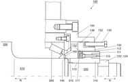
- FIG. 1 shows the bearing closure device 100 in a first embodiment. It is used to draw at least one bearing 200 on a roll journal 310 , to hold the bearing 200 on the roll journal or to release the bearing 200 from the roll journal 310 of a roller.
- the bearing closure device 100 has a threaded ring 110 , which can be slid axially onto a roll shoulder 320 of the roll journal 310 .
- the threaded ring 110 has a first axially extending section 111 , which carries an external thread 112 on its external side.
- the threaded ring 110 has a second ring-shaped section 113 .
- the second ring-shaped section is formed with a smaller outer diameter than the first ring-shaped section 111 , thereby forming a stop 117 in the transition area between the two sections 111 , 113 .
- the threaded ring 110 is installed in the bearing closure device in such a manner that the first section 111 is arranged further away from the roll barrel 330 of the roller than the second section 113 .
- the bearing closure device 100 also has a stop 120 that can be attached to the end of the roll shoulder 320 remote from the roll barrel in order to limit the axial movement of the threaded ring 110 , which is mounted on the roll shoulder 320 in an axially displaceable manner.
- the stop 120 can be either in the form of a hinged ring 120 ′ or in the form of a bayonet lock 120 ′′, as shown in FIG. 2 .
- the bearing closure device 100 also has a ring nut 130 with an internal thread 132 for screwing onto the external thread 112 of the threaded ring 110 .
- the ring nut 130 has a flange 138 that extends in a radial outward manner.
- This flange 138 can be formed with or without axial bores; see also FIG. 14 .
- the ring nut can also be formed completely without an outer flange; see FIG. 15 .
- the bearing closure device 100 has a pressure ring 140 that is mounted on the second ring-shaped section 113 of the threaded ring 110 in a displaceable manner in the axial direction R.
- a plurality of screws 115 are rotatably mounted in axial threaded bores for pressing against the pressure ring 140 in the axial direction R.
- the bearing closure device 100 has a ring-shaped intermediate ring 150 , which is formed in such a manner that it partially overlaps or engages at least the radially outer parts of the bearing 200 that do not rotate with the roller. This means that the bearing is displaced onto the roll journal by the intermediate ring or pressure ring or released or drawn off from the roll journal.
- the intermediate ring 150 and the bearing 200 thus form one unit.
- second screws 135 are provided, which are directly or indirectly connected to the intermediate ring 150 and the ring nut 130 in order to build up an axial force between the intermediate ring 150 and the ring nut 130 for the axial drawing off of the bearing 200 .
- FIG. 1 shows a first variant.
- the ring nut 130 for such first variant has the flange 138 that projects radially outwardly.
- the ring-shaped intermediate ring 150 has an axially and radially extending inner flange 152 in its radial inner area.
- Such flange is formed to overlap the outer flange 138 of the ring nut 130 in such a manner that the end face of the flange 138 of the ring nut 130 remote from the barrel is opposite the end face of the flange 152 of the intermediate ring close to the barrel.
- the second bolts 135 can be screwed into axial bores in the flange 152 of the extension ring, as shown in FIG. 1 , in order to build up an axial force between the extension ring 150 and the ring nut 130 , if the second bolts 135 are screwed against the flange 138 and are supported there.
- FIG. 14 shows a second variant for the arrangement of the intermediate ring 150 and the ring nut 130 .
- the flange 138 of the ring nut 130 with the second variant has a plurality of axially aligned bores distributed around the circumference of the flange.
- the ring-shaped intermediate ring 150 now does not overlap the flange 138 of the ring nut but is located with its radial inner area opposite the end face of the outer flange 138 close to the barrel.
- the intermediate ring 150 has a plurality of axially aligned internally threaded bores distributed around its circumference, wherein the bores in the intermediate ring 150 are aligned with the bores in the flange 138 of the ring nut 130 .
- the second bolts 135 can be passed through the bores in the flange 138 of the ring nut and screwed into the threaded bores in the intermediate ring 150 in order to build up the tensile stress between the intermediate ring and the ring nut.
- the second screws 135 are tightened, wherein the force builds up between the intermediate ring and the ring nut, because the screws are supported by the flange 138 with their screw heads. Due to the positive-locking connection between the intermediate ring 150 and the bearing 200 , the bearing is then released or drawn off from the roll journal together with the intermediate ring or with the assistance of the intermediate ring; this applies to all three variants.
- FIG. 15 shows the third variant.
- an additional ring 170 is provided for axial mounting on the end face of the ring nut 130 remote from the barrel.
- the additional ring 170 has a plurality of axially aligned bores distributed around its periphery, which bores are formed radially outside the ring nut.
- the ring-shaped intermediate ring 150 with its radial inner area is located opposite the end face of the periphery of the additional ring 170 close to the barrel.
- the intermediate ring In its radial internal area, has a plurality of axially aligned bores with internal threads distributed around its circumference, wherein such bores are aligned with the bores in the additional ring 170 .
- the second screws 135 can be passed through the bores in the additional ring 170 and screwed into the bores in the intermediate ring 150 in order to build up the force between the intermediate ring of the ring nut and the additional ring 170 to release the bearing 200 from the roll journal 310 , wherein the screws 135 are supported with their screw heads on the additional ring 170 .
- the pressure ring 140 has a pressure measuring cell 160 for recording a drawing force actually applied by the first screws 115 when the bearing 200 is drawn on the roll journal.
- a method for drawing the bearing 200 on the roll journal 310 of a roller with the assistance of the bearing closure device 100 comprises the following steps:
- the bearing is pre-positioned on the roll journal 310 in positive-locking connection with the bearing closure device 100 .
- the bearing 200 is positioned closer to the barrel on the roll journal than the bearing closure device 100 ; the latter is pre-positioned, as shown in FIG. 3 , axially further out on the roll shoulder 320 .
- the pre-positioning of the bearing and the bearing closure device is typically carried out with a crane or a drawing-on machine.
- the stop 120 is axially fixed on the end of the roll shoulder 320 remote from the roll barrel according to FIG. 4 .
- the stop 120 for example in the form of the hinged ring 120 ′ or the bayonet lock 120 ′′, serves as a right-side travel limit for the axial movement of the threaded ring 110 .
- the actual positioning of the bearing 200 on the roll journal 310 with a predetermined drawing force is carried out by axially displacing the pressure ring 140 , by way of example in FIGS. 3 and 4 to the left against the bearing 200 .
- This axial displacement of the pressure ring 140 and the bearing 200 is achieved by screwing the first screws 115 into the axial threaded bores in the first ring-shaped section 111 of the threaded ring 110 against the pressure ring 140 .
- the threaded ring 110 is supported by the axially fixed stop 120 , 120 ′.
- the application of the specified predetermined drawing force is carried out by tightening the first screws 115 to a predetermined torque with the assistance of a torque wrench or another suitable tool; see FIG. 5 .
- the ring nut 130 is turned against the pressure ring 140 and locked in such position in a positive-locking manner; see FIG. 6 .
- the ring nut 130 thus takes the place of the screws and takes over the maintenance of the necessary drawing force for these, also during the later operation of the roller and the bearing.
- the first screws 115 can now be turned back and relieved from load in this manner, as shown in FIG. 7 .
- the bearing 200 has thus been drawn on.
- a method for releasing and/or drawing off the bearing from the roll journal comprises the following steps:
- the starting configuration for the drawing-off process corresponds to the final configuration or the condition of the bearing closure device at the end of the drawing-on process, with the only difference that the second screws 135 are now also screwed into the bores in the flange 152 of the extension ring 150 .
- Such second screws 135 are only relevant for the drawing-off process, but not for the drawing-on process.
- FIG. 8 shows the starting position for the drawing-off process.
- the tension between the pressure ring 140 and the ring nut 130 must first be released.
- the first screws 115 are tightened uniformly to a predetermined amount of torque, such that they press against the pressure ring 140 in the axial direction with a predetermined (drawing) force.
- the first screws 115 are supported by the threaded ring 110 and the stop 120 on the roll journal.
- the pressure ring 140 then passes the drawing force applied by the first screws 115 to the bearing 200 , causing the bearing to be drawn a little further onto the roll journal 310 . This releases the ring nut 130 , i.e.
- the ring nut 130 is then unlocked and is turned back from its stop position in the axial direction away from the roll barrel 330 .
- the screws 115 can also be turned back away from the bearing; see FIG. 11 .
- FIG. 12 shows that the second bolts 135 are now tightened against the flange 138 of the ring nut 130 in order to build up a force between the end cap and the ring nut to release and/or draw off the bearing from the roll journal.
- the force is built up because, with the first variant shown in FIG. 12 for the arrangement of the end cap ring nut constellation, the threaded ring 110 , which engages with the ring nut 130 via its external thread 112 , is displaced a little in the axial direction towards the roll barrel 330 or towards the bearing 200 , and can be supported in the roll journal 310 at the stop 315 close to the roll barrel.
- FIGS. 14 and 15 have already been mentioned in the text above.
- FIG. 16 shows a second exemplary embodiment of the design of the interaction of the roll journal and the threaded ring.
- the roll journal 310 is formed to extend a little to the right, such that the pressure ring 140 is now completely mounted on the roll journal 310 in an axially displaceable manner.
- the second axial section 113 of the threaded ring 110 has been completely omitted, because it is no longer required as a bearing surface for the pressure ring 140 with this second embodiment; in this second embodiment without the second section 113 , the threaded ring 110 is narrower than in FIG. 1 with the specified second section; rather, the threaded ring 110 now extends only over the width of the previous first section 111 .
- the threaded ring 110 can still be displaced axially between the stop 120 or 120 ′ remote from the roll barrel and the stop 315 close to the roll barrel. If the ring nut 130 is not set against the pressure ring 140 , as shown in FIG. 16 , the pressure ring is mounted in an axially displaceable manner between the bearing 200 and the end face 117 of the threaded ring 110 close to the roll barrel.
- FIG. 17 shows a third variant for the arrangement of the roll journal in conjunction with the threaded ring.
- the extension of the roll journal 310 to the right is omitted according to FIG. 16 ; rather, it is formed to be similarly long or short as with the first exemplary embodiment according to FIG. 1 .
- the specified second section 113 of the threaded ring 110 is omitted here as well; i.e., the width of the threaded ring 110 is reduced to the original first axial section 111 .
- a filling ring 190 is now arranged or is mounted in an axially displaceable manner between the stop 315 close to the barrel for the threaded ring and the threaded ring 110 itself, or more precisely its end face 117 on the side of the roll barrel.
- the filling ring 190 serves as a carrier or support ring for the pressure ring 140 .
- the pressure ring 140 can be displaced in an axially free manner; in particular, its radial height corresponds, for example, to the difference between the outer diameter of the roll journal 310 and the outer diameter of the roll shoulder 320 .
- the end face of the filling ring 190 remote from the roll barrel now serves as a direct stop close to the roll barrel for the threaded ring 110 , wherein, in the event of a stop, the filling ring 190 in turn is supported on the stop 315 ; in this respect, the stop 315 remains as an indirect stop for the threaded ring 110 even when the filling ring 190 is used.
- FIG. 18 shows a fourth exemplary embodiment of the design of the roll journal 310 with the threaded ring 110 .
- the roll journal 310 is now formed with a uniform outer diameter throughout; a reduction of the outer diameter in the form of the roll shoulder 320 is now no longer necessary.
- the width of the threaded ring 110 is also limited to its first axial section 111 ; the axial extension 113 for carrying the pressure ring 140 is completely omitted, as is already the case with the exemplary embodiments 2 and 3 described above. Since the roll journal now has an essentially continuous outer diameter, with the fourth exemplary embodiment discussed here, the pressure ring 140 is again displaced onto the roll journal over its entire width. The same applies to the threaded ring 110 .
- Both the pressure ring 140 and the threaded ring 110 are now mounted directly on the roll journal 310 in an axially displaceable manner. Since the pressure ring 140 is now mounted on the roll journal in a displaceable manner, there is no need to provide the filling ring 190 as a radial support for the pressure ring 140 .
- the stop 120 remote from the barrel, serves as the right-side limit for the movement of the threaded ring 110 .
- a feather key 325 inserted into the threaded ring 110 serves as a stop close to the roll barrel, which feather key engages in a local axial groove 326 in the surface of the roll journal 310 and, if applicable, hits the limit of the groove 326 close to the barrel.
Landscapes
- Engineering & Computer Science (AREA)
- Mechanical Engineering (AREA)
- General Engineering & Computer Science (AREA)
- Rolling Contact Bearings (AREA)
- Rolls And Other Rotary Bodies (AREA)
- Mounting Of Bearings Or Others (AREA)
Abstract
Description
-
- 100 Bearing closure device
- 110 Threaded ring
- 111 First ring-shaped section of the threaded ring
- 112 External thread
- 113 Second ring-shaped section of the threaded ring
- 115 First screws
- 117 Stop for the pressure ring
- 120 Stop
- 120′ Hinged ring
- 120″ Bayonet lock
- 130 Ring nut
- 132 Internal thread
- 135 Second screws
- 138 Outer flange
- 140 Pressure ring
- 150 Intermediate ring
- 152 Inner flange of the intermediate ring
- 160 Pressure measuring cell
- 170 Additional ring
- 190 Filling ring
- 200 Bearing
- 310 Roll journal, in particular first ring-shaped section of the roll journal
- 315 Stop close to roll barrel in the roll journal
- 320 Roll shoulder (=second ring-shaped section of the roll journal)
- 325 Feather key
- 326 Axial groove
- 330 Roll barrels
- R Axial direction
Claims (14)
Applications Claiming Priority (5)
| Application Number | Priority Date | Filing Date | Title |
|---|---|---|---|
| DE102017209304.8 | 2017-06-01 | ||
| DE102017209304 | 2017-06-01 | ||
| DE102017217562.1A DE102017217562A1 (en) | 2017-06-01 | 2017-10-04 | Bearing locking device and method for its operation |
| DE102017217562.1 | 2017-10-04 | ||
| PCT/EP2018/063895 WO2018219850A1 (en) | 2017-06-01 | 2018-05-28 | Bearing closure device and method for operating same |
Publications (2)
| Publication Number | Publication Date |
|---|---|
| US20210140470A1 US20210140470A1 (en) | 2021-05-13 |
| US11261907B2 true US11261907B2 (en) | 2022-03-01 |
Family
ID=64279316
Family Applications (1)
| Application Number | Title | Priority Date | Filing Date |
|---|---|---|---|
| US16/618,341 Active 2038-12-05 US11261907B2 (en) | 2017-06-01 | 2018-05-28 | Bearing closure device and method for operating the same |
Country Status (8)
| Country | Link |
|---|---|
| US (1) | US11261907B2 (en) |
| EP (1) | EP3630381B1 (en) |
| JP (1) | JP6920476B2 (en) |
| KR (1) | KR102327797B1 (en) |
| CN (1) | CN110678273B (en) |
| DE (1) | DE102017217562A1 (en) |
| RU (1) | RU2732458C1 (en) |
| WO (1) | WO2018219850A1 (en) |
Families Citing this family (5)
| Publication number | Priority date | Publication date | Assignee | Title |
|---|---|---|---|---|
| DE102021205276A1 (en) * | 2021-05-21 | 2021-07-22 | Sms Group Gmbh | Journal bushing as part of an oil film bearing |
| DE202021001817U1 (en) | 2021-05-21 | 2021-07-05 | Sms Group Gmbh | Journal bushing as part of an oil film bearing |
| CN113550982B (en) * | 2021-08-18 | 2022-07-29 | 闻军 | Make things convenient for bearing block fastening's bearing frame |
| CN114571407B (en) * | 2022-03-21 | 2024-06-21 | 吉林大学 | Bearing disassembly tool suitable for different spindle sizes |
| CN114714064B (en) * | 2022-05-06 | 2023-07-18 | 南京晨光集团有限责任公司 | Knuckle bearing rolling tool |
Citations (17)
| Publication number | Priority date | Publication date | Assignee | Title |
|---|---|---|---|---|
| FR1254487A (en) | 1960-01-12 | 1961-02-24 | Timken Roller Bearing Co | Mounting of bearings intended for use on tapered trunnions of rolling mill rolls and the like |
| US3080199A (en) | 1961-09-01 | 1963-03-05 | Morgan Construction Co | Integral bearing mounting and dismounting means |
| US3966282A (en) | 1973-08-31 | 1976-06-29 | Republic Steel Corporation | Bearing chocking assembly for mill rolls |
| SU820944A1 (en) | 1979-06-13 | 1981-04-15 | Ижевский механический институт | Rolling roll bearing assembly |
| GB2060820A (en) | 1979-09-24 | 1981-05-07 | Morgan Construction Co | Mounting roll neck bearings |
| JPS6069825U (en) | 1983-10-20 | 1985-05-17 | 日本精工株式会社 | Roller bearing device for axle of railway vehicle |
| US4938615A (en) | 1989-10-26 | 1990-07-03 | The Timken Company | Roll neck bearing |
| RU2048220C1 (en) | 1993-10-08 | 1995-11-20 | Акционерное общество "Северсталь" | Device for radial and axial adjustment of stand roll |
| JPH1015610A (en) | 1996-07-02 | 1998-01-20 | Kobe Steel Ltd | Method and device for delivering steel bar onto cooling bed |
| US6132101A (en) * | 1999-07-28 | 2000-10-17 | Voest Alpine Industries, Inc. | Roll bearing assembly having integral components |
| JP2001065583A (en) | 1999-07-29 | 2001-03-16 | Morgan Construction Co | Mounting and demounting device for mounting and demounting bearing ot neck part of rolling machine roll |
| US20100000375A1 (en) | 2008-07-07 | 2010-01-07 | Steinbock Robert C | Tamper resistant jackbolts for a tensioner |
| US8690743B2 (en) | 2010-12-23 | 2014-04-08 | Sms Siemag Aktiengesellschaft | Bearing arrangement and rolling unit for a rolling-mill roll |
| CN104438990A (en) | 2014-10-15 | 2015-03-25 | 张家港海陆环形锻件有限公司 | Large vertical type composite ring rolling mill and control method |
| CN204448832U (en) | 2014-12-29 | 2015-07-08 | 鞍钢股份有限公司 | Roller bearing box locking ring in high-speed wire rod mill |
| CN204610423U (en) | 2015-01-27 | 2015-09-02 | 博斯特(上海)有限公司 | A kind of rotary-piston for printing plate cylinder locking |
| CN204710856U (en) | 2015-06-19 | 2015-10-21 | 邯钢集团邯宝钢铁有限公司 | A kind of snap joint locking device of improvement |
Family Cites Families (3)
| Publication number | Priority date | Publication date | Assignee | Title |
|---|---|---|---|---|
| DE19819063A1 (en) * | 1998-04-29 | 1999-11-04 | Schloemann Siemag Ag | Straightening machine for rolled beams |
| DE19945070A1 (en) * | 1999-09-20 | 2001-03-22 | Sms Demag Ag | Device for mounting and removing a support roller bearing unit |
| US7500374B2 (en) * | 2007-04-03 | 2009-03-10 | Morgan Construction Company | Apparatus for urging an oil film bearing onto and off of a roll neck in a rolling mill |
-
2017
- 2017-10-04 DE DE102017217562.1A patent/DE102017217562A1/en not_active Withdrawn
-
2018
- 2018-05-28 KR KR1020197038253A patent/KR102327797B1/en active Active
- 2018-05-28 WO PCT/EP2018/063895 patent/WO2018219850A1/en not_active Ceased
- 2018-05-28 US US16/618,341 patent/US11261907B2/en active Active
- 2018-05-28 EP EP18735503.7A patent/EP3630381B1/en active Active
- 2018-05-28 JP JP2019566072A patent/JP6920476B2/en active Active
- 2018-05-28 CN CN201880036307.3A patent/CN110678273B/en active Active
- 2018-05-28 RU RU2019138553A patent/RU2732458C1/en active
Patent Citations (20)
| Publication number | Priority date | Publication date | Assignee | Title |
|---|---|---|---|---|
| FR1254487A (en) | 1960-01-12 | 1961-02-24 | Timken Roller Bearing Co | Mounting of bearings intended for use on tapered trunnions of rolling mill rolls and the like |
| US3080199A (en) | 1961-09-01 | 1963-03-05 | Morgan Construction Co | Integral bearing mounting and dismounting means |
| DE1254108B (en) | 1961-09-01 | 1967-11-16 | Morgan Construction Co | Roll neck bearings |
| US3966282A (en) | 1973-08-31 | 1976-06-29 | Republic Steel Corporation | Bearing chocking assembly for mill rolls |
| SU820944A1 (en) | 1979-06-13 | 1981-04-15 | Ижевский механический институт | Rolling roll bearing assembly |
| GB2060820A (en) | 1979-09-24 | 1981-05-07 | Morgan Construction Co | Mounting roll neck bearings |
| JPS6069825U (en) | 1983-10-20 | 1985-05-17 | 日本精工株式会社 | Roller bearing device for axle of railway vehicle |
| US4938615A (en) | 1989-10-26 | 1990-07-03 | The Timken Company | Roll neck bearing |
| DE69010141T2 (en) | 1989-10-26 | 1994-11-17 | Timken Co | Bearing and bearing arrangement. |
| RU2048220C1 (en) | 1993-10-08 | 1995-11-20 | Акционерное общество "Северсталь" | Device for radial and axial adjustment of stand roll |
| JPH1015610A (en) | 1996-07-02 | 1998-01-20 | Kobe Steel Ltd | Method and device for delivering steel bar onto cooling bed |
| US6132101A (en) * | 1999-07-28 | 2000-10-17 | Voest Alpine Industries, Inc. | Roll bearing assembly having integral components |
| JP2001065583A (en) | 1999-07-29 | 2001-03-16 | Morgan Construction Co | Mounting and demounting device for mounting and demounting bearing ot neck part of rolling machine roll |
| US20100000375A1 (en) | 2008-07-07 | 2010-01-07 | Steinbock Robert C | Tamper resistant jackbolts for a tensioner |
| EP2143521A1 (en) | 2008-07-07 | 2010-01-13 | Steinbock Machinery Co. | A multi jackbolt tensioner including tamper resistant jackbolts |
| US8690743B2 (en) | 2010-12-23 | 2014-04-08 | Sms Siemag Aktiengesellschaft | Bearing arrangement and rolling unit for a rolling-mill roll |
| CN104438990A (en) | 2014-10-15 | 2015-03-25 | 张家港海陆环形锻件有限公司 | Large vertical type composite ring rolling mill and control method |
| CN204448832U (en) | 2014-12-29 | 2015-07-08 | 鞍钢股份有限公司 | Roller bearing box locking ring in high-speed wire rod mill |
| CN204610423U (en) | 2015-01-27 | 2015-09-02 | 博斯特(上海)有限公司 | A kind of rotary-piston for printing plate cylinder locking |
| CN204710856U (en) | 2015-06-19 | 2015-10-21 | 邯钢集团邯宝钢铁有限公司 | A kind of snap joint locking device of improvement |
Also Published As
| Publication number | Publication date |
|---|---|
| KR102327797B1 (en) | 2021-11-17 |
| EP3630381B1 (en) | 2022-08-17 |
| EP3630381A1 (en) | 2020-04-08 |
| US20210140470A1 (en) | 2021-05-13 |
| WO2018219850A1 (en) | 2018-12-06 |
| KR20200011484A (en) | 2020-02-03 |
| JP2020521922A (en) | 2020-07-27 |
| RU2732458C1 (en) | 2020-09-16 |
| CN110678273B (en) | 2021-03-26 |
| DE102017217562A1 (en) | 2018-12-06 |
| CN110678273A (en) | 2020-01-10 |
| BR112019025260A2 (en) | 2020-06-23 |
| JP6920476B2 (en) | 2021-08-18 |
Similar Documents
| Publication | Publication Date | Title |
|---|---|---|
| US11261907B2 (en) | Bearing closure device and method for operating the same | |
| US20100239390A1 (en) | Washer and method for tightening and loosening threaded connectors | |
| EP2848426B1 (en) | Wheel hub, in particular aircraft wheel hub | |
| US7386939B2 (en) | Hydraulic fast locking and loosening device for bearing assemblies of rolling-mill cylinders, and corresponding method of use | |
| US20170087675A1 (en) | Tensioning Device for a Screw Connection, Method for Tightening a Screw Connection, and Threaded Nut | |
| US20110220376A1 (en) | Method for tightening and loosening threaded connectors | |
| US20090293418A1 (en) | Foundation Bolt Tensioner | |
| US9314910B2 (en) | Hot bolting clamp | |
| DE102011000626A1 (en) | Wheel bearing for a vehicle wheel and wheel hub for attaching a vehicle wheel | |
| US11840347B2 (en) | Assembly comprising a translationally and rotationally immobile link axis, engine attachment or aircraft comprising such an assembly | |
| US20120134617A1 (en) | Roller bearer fastening | |
| CN114833561A (en) | Arrangement of a fastening device and a safety device for a threaded connection | |
| EP2812156B1 (en) | Pretensioning tool and method for tightening a nut | |
| US20090120234A1 (en) | Device for a clamping bolt | |
| CN112478138A (en) | Anti-loosening pull rod and mounting method thereof | |
| US7179035B2 (en) | Locking nut | |
| US9555666B2 (en) | Assembly tool for wheel hub | |
| DE102016123370A1 (en) | brake disc | |
| BR112019025260B1 (en) | BEARING CLOSING DEVICE, PROCESS FOR ASSEMBLING A BEARING AND PROCESS FOR REMOVING A BEARING | |
| EP3341619B1 (en) | Locking arrangement for a nut | |
| EP4242472B1 (en) | Nut, fastening assembly and method for fastening a load | |
| IT201800011185A1 (en) | Fixing device equipped with a swivel washer | |
| DE1112699B (en) | Brake drum for spoked wheels of heavy vehicles and trailers | |
| US20120034026A1 (en) | Single-sided fitting | |
| CN206655898U (en) | Drive axle wheel edge locking nut fastening structure |
Legal Events
| Date | Code | Title | Description |
|---|---|---|---|
| AS | Assignment |
Owner name: SMS GROUP GMBH, GERMANY Free format text: ASSIGNMENT OF ASSIGNORS INTEREST;ASSIGNORS:TUCAK, ANDREJ;KNIE, DANIEL;WILL, ROLAND;SIGNING DATES FROM 20191121 TO 20191122;REEL/FRAME:051145/0644 |
|
| FEPP | Fee payment procedure |
Free format text: ENTITY STATUS SET TO UNDISCOUNTED (ORIGINAL EVENT CODE: BIG.); ENTITY STATUS OF PATENT OWNER: LARGE ENTITY |
|
| STPP | Information on status: patent application and granting procedure in general |
Free format text: PRE-INTERVIEW COMMUNICATION MAILED |
|
| STPP | Information on status: patent application and granting procedure in general |
Free format text: RESPONSE TO NON-FINAL OFFICE ACTION ENTERED AND FORWARDED TO EXAMINER |
|
| STPP | Information on status: patent application and granting procedure in general |
Free format text: NON FINAL ACTION MAILED |
|
| STPP | Information on status: patent application and granting procedure in general |
Free format text: RESPONSE TO NON-FINAL OFFICE ACTION ENTERED AND FORWARDED TO EXAMINER |
|
| STPP | Information on status: patent application and granting procedure in general |
Free format text: NOTICE OF ALLOWANCE MAILED -- APPLICATION RECEIVED IN OFFICE OF PUBLICATIONS |
|
| STCF | Information on status: patent grant |
Free format text: PATENTED CASE |
|
| MAFP | Maintenance fee payment |
Free format text: PAYMENT OF MAINTENANCE FEE, 4TH YEAR, LARGE ENTITY (ORIGINAL EVENT CODE: M1551); ENTITY STATUS OF PATENT OWNER: LARGE ENTITY Year of fee payment: 4 |