US11260784B2 - Active vehicle footrest - Google Patents
Active vehicle footrest Download PDFInfo
- Publication number
- US11260784B2 US11260784B2 US16/370,531 US201916370531A US11260784B2 US 11260784 B2 US11260784 B2 US 11260784B2 US 201916370531 A US201916370531 A US 201916370531A US 11260784 B2 US11260784 B2 US 11260784B2
- Authority
- US
- United States
- Prior art keywords
- footrest
- moveable
- vehicle
- ingress
- mounting
- Prior art date
- Legal status (The legal status is an assumption and is not a legal conclusion. Google has not performed a legal analysis and makes no representation as to the accuracy of the status listed.)
- Active, expires
Links
Images


Classifications
-
- B—PERFORMING OPERATIONS; TRANSPORTING
- B60—VEHICLES IN GENERAL
- B60N—SEATS SPECIALLY ADAPTED FOR VEHICLES; VEHICLE PASSENGER ACCOMMODATION NOT OTHERWISE PROVIDED FOR
- B60N3/00—Arrangements or adaptations of other passenger fittings, not otherwise provided for
- B60N3/06—Arrangements or adaptations of other passenger fittings, not otherwise provided for of footrests
- B60N3/063—Arrangements or adaptations of other passenger fittings, not otherwise provided for of footrests with adjustment systems
-
- B—PERFORMING OPERATIONS; TRANSPORTING
- B62—LAND VEHICLES FOR TRAVELLING OTHERWISE THAN ON RAILS
- B62J—CYCLE SADDLES OR SEATS; AUXILIARY DEVICES OR ACCESSORIES SPECIALLY ADAPTED TO CYCLES AND NOT OTHERWISE PROVIDED FOR, e.g. ARTICLE CARRIERS OR CYCLE PROTECTORS
- B62J1/00—Saddles or other seats for cycles; Arrangement thereof; Component parts
- B62J1/12—Box-shaped seats; Bench-type seats, e.g. dual or twin seats
-
- B—PERFORMING OPERATIONS; TRANSPORTING
- B62—LAND VEHICLES FOR TRAVELLING OTHERWISE THAN ON RAILS
- B62J—CYCLE SADDLES OR SEATS; AUXILIARY DEVICES OR ACCESSORIES SPECIALLY ADAPTED TO CYCLES AND NOT OTHERWISE PROVIDED FOR, e.g. ARTICLE CARRIERS OR CYCLE PROTECTORS
- B62J1/00—Saddles or other seats for cycles; Arrangement thereof; Component parts
- B62J1/14—Separate pillions
-
- B—PERFORMING OPERATIONS; TRANSPORTING
- B62—LAND VEHICLES FOR TRAVELLING OTHERWISE THAN ON RAILS
- B62J—CYCLE SADDLES OR SEATS; AUXILIARY DEVICES OR ACCESSORIES SPECIALLY ADAPTED TO CYCLES AND NOT OTHERWISE PROVIDED FOR, e.g. ARTICLE CARRIERS OR CYCLE PROTECTORS
- B62J1/00—Saddles or other seats for cycles; Arrangement thereof; Component parts
- B62J1/28—Other additional equipment, e.g. back-rests for children
-
- B—PERFORMING OPERATIONS; TRANSPORTING
- B62—LAND VEHICLES FOR TRAVELLING OTHERWISE THAN ON RAILS
- B62J—CYCLE SADDLES OR SEATS; AUXILIARY DEVICES OR ACCESSORIES SPECIALLY ADAPTED TO CYCLES AND NOT OTHERWISE PROVIDED FOR, e.g. ARTICLE CARRIERS OR CYCLE PROTECTORS
- B62J25/00—Foot-rests; Knee grips; Passenger hand-grips
- B62J25/04—Floor-type foot rests
-
- B—PERFORMING OPERATIONS; TRANSPORTING
- B62—LAND VEHICLES FOR TRAVELLING OTHERWISE THAN ON RAILS
- B62K—CYCLES; CYCLE FRAMES; CYCLE STEERING DEVICES; RIDER-OPERATED TERMINAL CONTROLS SPECIALLY ADAPTED FOR CYCLES; CYCLE AXLE SUSPENSIONS; CYCLE SIDECARS, FORECARS, OR THE LIKE
- B62K5/00—Cycles with handlebars, equipped with three or more main road wheels
- B62K5/02—Tricycles
- B62K5/05—Tricycles characterised by a single rear wheel
-
- B—PERFORMING OPERATIONS; TRANSPORTING
- B62—LAND VEHICLES FOR TRAVELLING OTHERWISE THAN ON RAILS
- B62K—CYCLES; CYCLE FRAMES; CYCLE STEERING DEVICES; RIDER-OPERATED TERMINAL CONTROLS SPECIALLY ADAPTED FOR CYCLES; CYCLE AXLE SUSPENSIONS; CYCLE SIDECARS, FORECARS, OR THE LIKE
- B62K5/00—Cycles with handlebars, equipped with three or more main road wheels
- B62K5/02—Tricycles
- B62K5/06—Frames for tricycles
-
- B—PERFORMING OPERATIONS; TRANSPORTING
- B62—LAND VEHICLES FOR TRAVELLING OTHERWISE THAN ON RAILS
- B62K—CYCLES; CYCLE FRAMES; CYCLE STEERING DEVICES; RIDER-OPERATED TERMINAL CONTROLS SPECIALLY ADAPTED FOR CYCLES; CYCLE AXLE SUSPENSIONS; CYCLE SIDECARS, FORECARS, OR THE LIKE
- B62K7/00—Freight- or passenger-carrying cycles
- B62K7/02—Frames
- B62K7/04—Frames having a carrying platform
-
- B—PERFORMING OPERATIONS; TRANSPORTING
- B62—LAND VEHICLES FOR TRAVELLING OTHERWISE THAN ON RAILS
- B62J—CYCLE SADDLES OR SEATS; AUXILIARY DEVICES OR ACCESSORIES SPECIALLY ADAPTED TO CYCLES AND NOT OTHERWISE PROVIDED FOR, e.g. ARTICLE CARRIERS OR CYCLE PROTECTORS
- B62J45/00—Electrical equipment arrangements specially adapted for use as accessories on cycles, not otherwise provided for
- B62J45/40—Sensor arrangements; Mounting thereof
- B62J45/41—Sensor arrangements; Mounting thereof characterised by the type of sensor
-
- B—PERFORMING OPERATIONS; TRANSPORTING
- B62—LAND VEHICLES FOR TRAVELLING OTHERWISE THAN ON RAILS
- B62M—RIDER PROPULSION OF WHEELED VEHICLES OR SLEDGES; POWERED PROPULSION OF SLEDGES OR SINGLE-TRACK CYCLES; TRANSMISSIONS SPECIALLY ADAPTED FOR SUCH VEHICLES
- B62M6/00—Rider propulsion of wheeled vehicles with additional source of power, e.g. combustion engine or electric motor
- B62M6/40—Rider propelled cycles with auxiliary electric motor
- B62M6/55—Rider propelled cycles with auxiliary electric motor power-driven at crank shafts parts
Definitions
- aspects of the present disclosure relate a vehicle and passenger carrying apparatus usable with the vehicle. More specifically, aspects relate to a vehicle passenger carrying portion with a movable footrest and ingress/egress area.
- Bicycles are a well know alternative for convenient and efficient transportation.
- the need exists to transport cargo or people who may be otherwise unable to utilize a bicycle as a method of transportation.
- Light transport vehicles such as bicycle trailers
- Bicycle trailers have several disadvantages, including the need for an attachment mechanism for connection to a bicycle.
- a bicycle connected to a trailer may be cumbersome and difficult to handle or maneuver in certain situations.
- bicycle trailers may be unstable and cumbersome for frequent transport of cargo or children.
- bicycle trailers are not practical for transport of adults or for hauling heavier cargo.
- the passenger carrying portion includes a seating surface and a moveable footrest below the seating surface.
- the footrest is moveable from an ingress/egress position to a transport position that is closer to the seating surface than the ingress/egress position.
- the passenger carrying portion further includes a footrest movement mechanism, wherein the footrest movement mechanism controls movement of the moveable footrest between the ingress/egress position the transport position.
- FIG. 1 is a perspective view of an example vehicle with an interchangeable passenger carrying portion usable with an adjustable footrest in accordance with aspects of the disclosure
- FIG. 2 is a perspective view of the vehicle of FIG. 1 with an interchangeable cargo carrying portion
- FIG. 3 is a perspective view of an example vehicle usable with an interchangeable cargo carrying portion and adjustable footrest in accordance with one aspect of the disclosure
- FIG. 4 is a front perspective partial see-through view of an example passenger carrying portion and adjustable footrest in accordance with one aspect of the disclosure
- FIG. 5 is a front perspective cut-away view of the passenger carrying portion and adjustable footrest of FIG. 4 shown as mounted to the vehicle of FIG. 3 in accordance with one aspect of the disclosure;
- FIG. 6 is a bottom perspective cut-away view of the passenger carrying portion and adjustable footrest of FIGS. 4-5 shown as mounted to the vehicle of FIG. 2 in accordance with one aspect of the disclosure;
- FIG. 7 is a front perspective cut-away view of the adjustable footrest and actuator mechanism of FIGS. 4-6 shown as mounted to the vehicle of FIG. 2 in accordance with one aspect of the disclosure.
- FIG. 8 is a rear perspective view of the adjustable footrest and actuator mechanism of FIGS. 4-7 shown as mounted to the vehicle of FIG. 2 in accordance with one aspect of the disclosure;
- FIG. 9 is a diagram view of an example sensor in accordance with one aspect of the disclosure:
- FIG. 10A is an circuit diagram of various example system components according to one aspect of the disclosure.
- FIG. 10B is a block diagram of various example system components according to one aspect of the disclosure.
- FIG. 10C is a block diagram of various example system components according to one aspect of the disclosure.
- FIG. 11 is an example microcontroller in accordance with an aspect of the disclosure.
- a vehicle which may for example be a pedal operated vehicle, may include a passenger carrying portion with one or more seat(s) and footrest(s).
- a passenger may sit in the one or more seats of the passenger carrying portion and place his or her feet on the footrest while the vehicle and vehicle operator transport the passenger, for example.
- it may be difficult for a passenger of a vehicle to step up onto the footrest when seating themselves on a seat of the passenger carrying portion.
- One example solution in accordance with aspects of the present disclosure to improve ingress/egress of passengers into the passenger carrying portion is to decrease the distance between the footrest and the ground surface on which the vehicle travels.
- decreasing the distance between the footrest and the ground surface may decrease ground-clearance of the vehicle, for example.
- a moveable footrest is disclosed for improved ingress/egress while maintaining acceptable ground-clearance of the vehicle.
- An example moveable footrest in accordance with one aspect of the disclosure may be moveable from an ingress/egress position to a transport position.
- the disclosed footrest may be moveable in a downward direction and selectively held in an ingress/egress position.
- the footrest may be moveable in an upward position to a transport position. Further detail of various examples of the footrest and its operation, passenger carrying portion, and vehicle usable with the passenger carrying portion are described herein.
- FIGS. 1-3 show one example of a vehicle in accordance with and usable with aspects of the present disclosure. While FIGS. 1-3 show a vehicle having pedal features (e.g., pedal powered, starting, or assist), a “vehicle,” as used herein is not limited to such a vehicle having pedals, and refers to any moving vehicle that is powered by any form of energy. A vehicle may carry human occupants or cargo or both.
- pedal features e.g., pedal powered, starting, or assist
- a “vehicle,” as used herein is not limited to such a vehicle having pedals, and refers to any moving vehicle that is powered by any form of energy.
- a vehicle may carry human occupants or cargo or both.
- FIGS. 1 and 2 show perspective views of an example vehicle 100 having and/or usable with various features in accordance with aspects of the current disclosure. It is noted that at least one example and/or further details for a number of the components referenced in the vehicle 100 in FIGS. 1 and 2 are described in further detail with reference to FIGS. 3-8 .
- an example vehicle 100 may be configured to have an interchangeable passenger carrying portion (e.g., reference 70 b in FIG. 1 ) and/or a cargo carrying portion (e.g., reference 70 a in FIG. 2 ) mounted thereto, such as on or in the area of U-shaped portion 106 ( FIG. 3 ) of the vehicle 100 .
- an interchangeable passenger carrying portion e.g., reference 70 b in FIG. 1
- a cargo carrying portion e.g., reference 70 a in FIG. 2
- the interchangeable passenger/cargo carrying portion may, for example, include a seat 68 b ( FIG. 1 ) for carrying a single or multiple passengers and/or provide a cargo area 68 a ( FIG. 2 ) for storage and/or transportation of cargo via the vehicle 100 .
- a seat 68 b FIG. 1
- the interchangeable cargo carrying portion and/or further features that are usable with the currently disclosed example vehicle are disclosed in U.S. patent application Ser. No. 16/542,702, titled “Convertible Passenger and Cargo Area for Vehicle,” filed on Aug. 16, 2019, and U.S. patent application Ser. No. 16/370,408, to titled “Vehicle Steering System,” filed on Mar. 29, 2019; the entirety of which are both incorporated by reference herein.
- the vehicle 100 may include a rear wheel 50 a and a pair of front wheels 50 b ( FIG. 2 ) and 50 c ( FIG. 1 ).
- a “wheel” or “wheels” as used herein may include a hub and extending surface (e.g., disk) portion contiguous with an outer rim.
- the hub may be connected to the rim via a series of tensioned spokes and/or other features.
- the rim may be configured to receive a tire, which may or may not be configured to contain an inflatable tube.
- the tire may be formed of a solid elastic material, and/or a material having a plurality of open and/or closed cells within an elastic material, which may include rubber, for example.
- the wheel hub, disk, spokes, and/or wheel rim may be formed, for example, of a metallic material, a plastic material, a composite material, or any combination thereof.
- the vehicle 100 may include a frame 101 , which may comprise a rigid or semi-rigid material, such as one or more plastic, composite, metals, or combinations thereof.
- the vehicle 100 may further include a steering tube 103 ( FIG. 2 ) and a steering portion 120 ( FIG. 2 ), which may, for example, include one or more extending handlebars.
- the vehicle 100 may further include a seat 127 mounted to a seatpost 128 .
- the rear wheel 50 a ( FIGS. 1 and 2 ) and the two front wheels 50 b and 50 c ( FIGS. 1 and 2 ) of vehicle 100 may rotate radially about axes B and C ( FIG. 3 ).
- Each of the front wheels 50 c and 50 b ( FIGS. 1 and 2 ) may include hub(s) 112 a and 112 b , respectively that are mountable via knuckles 114 a and 114 b ( FIG. 3 ), respectively, to U-shaped portion 106 of the vehicle frame 101 .
- each hub 112 a and 112 b may have a respective brake disk 116 a and 116 b mounted for operation in relation thereto.
- Each brake disk 116 a and 116 b may be configured to be selectively engaged with a friction or other resistive force for braking movement thereof, such as via respective brake calipers 118 a and 118 b configured to provide selective clamping force to each brake disk 116 a and 116 b so as to thereby slow or prevent movement of the attached wheels.
- a friction or other resistive force for braking movement thereof, such as via respective brake calipers 118 a and 118 b configured to provide selective clamping force to each brake disk 116 a and 116 b so as to thereby slow or prevent movement of the attached wheels.
- other non-frictional force may be used for such braking power, such as electro-magnetic based resistive force.
- a similar brake disk or other braking configuration as described with relation to the rotation of front wheels 50 c and 50 b ( FIGS. 1 and 2 , respectively) about axes C and B ( FIG. 3 ) may be mounted to the rear of the frame 101 , thereby similarly allowing braking to be applied to a rear wheel rotating about axis A.
- a rear brake caliper 118 c which may be similar to front brake caliper(s) 118 a - b , may also be located and configured to selectively clamp a brake disk in order to provide a friction force to the brake disk to inhibit or stop rotation of the rear wheel, thereby providing a stopping force to the vehicle 100 .
- Each of brake calipers 118 a , 118 b , and 118 c may provide a resistive force to each wheel in response to a user of the vehicle depressing or otherwise engaging a brake lever or other braking mechanism (not shown).
- both front brake calipers 118 a and 118 b may provide a clamping force to disks 116 a and 116 b respectively in response to a user depressing a first brake lever (not shown) mounted proximal to a first end of handlebar 120 .
- Rear caliper 118 c may be configured to apply a clamping force to a rear brake disk (not shown) mounted to a rear wheel 50 a ( FIGS. 1 and 2 ) rotating about axis A ( FIG. 3 ) in response to a user depressing a second brake lever (not shown) mounted proximal to a second end of handlebar 120 .
- each of front hubs 112 a and 112 b may be rotatably mountable to a respective knuckle 114 a and 114 b , and each respective knuckle 114 a and 114 b may be pivotably mounted to arms 115 a and 115 b and configured to pivot with respect to frame 101 .
- pivoting of knuckles 114 a and 114 b may be in directions denoted by arrows 170 a and 170 b about axes E and D, respectively.
- Brake calibers 118 a and 118 b and hubs 112 a and 112 b , along with corresponding wheels 50 c and 50 b ( FIGS.
- each respective knuckle or knuckle assembly 114 a and 114 b may be mounted to each respective knuckle or knuckle assembly 114 a and 114 b and similarly rotate therewith about axes E and D, respectively.
- a pivoting force applied by a user, for example, to handlebar 120 may cause each hub 112 a and 112 b , and thus each respective wheel and other corresponding features, to pivot in directions denoted by arrows 170 a and 170 b , so as to allow the vehicle to turn in a desired direction.
- the vehicle frame 101 may further include a seat tube 129 for receiving a seat post 128 .
- the seat post 128 may be configured to have a seat 127 ( FIGS. 1 and 2 ) mounted thereto.
- the seat post 128 may be configured to telescope within seat tube 129 , thereby allowing for adjustment of the seat height of the vehicle 100 .
- the vehicle 100 may include pedals 102 a and 102 b , which may be rotatably connected to a corresponding first 104 a and second crank 104 b .
- the cranks 104 a and 104 b may be rotatably connected to a shaft extending from the vehicle frame 101 .
- the shaft may also be connected to and extend into or through a sprocket 105 that is configured to mesh with a chain or belt (not shown) for driving the rear wheel (not shown in FIG. 3 ) about axis A.
- the vehicle 100 may alternatively or also be equipped with an assist motor 109 , such as an electric or other powered motor.
- the motor 109 may be selectively operable via the pedals 102 a , 102 b , for example, to provide starting motion and/or additional selective rotational force or assist for driving the rear wheel 51 a ( FIGS. 1 and 2 ) that rotates about axis A ( FIG. 3 ).
- the pedals 102 a and 102 b may also be selectively usable with the motor in a manner so as to charge any battery connected thereto.
- the motor 109 may be selectively electrically powered by battery 110 .
- the motor 109 and rotational cranks 104 and sprocket 105 shown in FIG. 3 may serve only as one example implementation.
- a motor may be located proximal to or within a rear hub that rotates around axis A.
- one or more motors may be located proximal to or at one of or both of front hubs 112 a and 112 b .
- the battery 10 may, for example, be implemented into the frame 101 and/or within the interchangeable passenger carrying portion (e.g., reference 70 b in FIG.
- the interchangeable carrying portions may include batteries of different capacities and the frame and interchangeable carrying portion may include corresponding connectors and/or connection terminals (not shown) to operatively connect each battery with the motor 109 when a specific interchangeable carrying portion is mounted to the vehicle frame 101 .
- the interchangeable passenger/cargo carrying portions 70 a or 70 b may be mounted to and supported by a U-shaped portion 106 via rear mounts 130 a and 130 b .
- the rear mounts 130 a and 130 b may, for example, each include a substantially concave receiving portion for assisting in receiving and directing corresponding first and second protruding extensions (e.g., extending from mount 211 a in FIG. 6 ) attached to the interchangeable cargo carrying portions 70 a and/or 70 b ( FIGS. 1 and 2 ). Receipt of such extensions into receiving locking openings in mounts 130 a , 130 b , may help properly position the passenger/cargo carrying portion.
- the U-shaped portion 106 of the vehicle frame 101 may further include side mounts 131 a and 131 b .
- the side mounts 131 a and 131 b may, for example, comprise a through hole for receiving a mounting pin or bolt for mounting via mounting portions 220 a and 220 b ( FIG. 7 ) of the interchangeable passenger/cargo carrying portion 70 a or 70 b ( FIGS. 2 and 1 , respectively) in conjunction with positioning via the rear mounts 130 a , 130 b .
- rear mounts 130 a and 130 b and front mounts 131 a and 131 b may allow for interchangeable mounting of one or more different types of carrying portions (e.g., 70 a or 70 b ) to vehicle frame 101 , for example.
- the steering mechanism of vehicle 100 may advantageously be located below U-shaped portion 106 of frame 101 . Further, by maintaining the steering mechanism of vehicle 100 at a location below the U-shaped portion 106 of frame 101 , the interchangeable cargo carrying portion, which may for example be a passenger carrying portion as discussed in further detail herein, may be removed and installed with reduced risk of damage to the steering components and/or the cargo carrying portion.
- FIG. 4 shows a partial see-through view of an example of an interchangeable passenger carrying portion 200 for use with an example vehicle, in accordance with aspects of the current disclosure.
- the passenger carrying portion 200 may be interchangeably mounted to and usable with the vehicle shown in FIGS. 1-3 , for example.
- the interchangeable passenger carrying portion 200 may include a seat portion 201 and moveable footrest 203 .
- the seat portion 201 may include a seating surface having a backrest 210 and a seat surface 212 .
- the interchangeable passenger carrying portion 200 may include a footrest that is movable from a lowered ingress/egress position 203 b to a raised transportation position 203 a and vice-versa as represented by arrows 213 .
- FIG. 5 is a cutaway view of various aspects of the passenger carrying portion 200 of FIG. 2 , showing further details of one example of the seat portion 201 and moveable footrest 203 in an ingress/egress (lowered) position (e.g., 203 b in FIG. 4 ).
- the seat portion 201 and moveable footrest 203 may include a set of mounting frames 217 a and 217 b (hidden from view in FIG. 5 ) that may be rigidly connected via a first cross-member 215 .
- Each of the mounting frames 217 a and 217 b may be mountable to a U-shaped portion 106 of vehicle frame 101 via mounting portions 220 a and 220 b (hidden from view in FIG. 5 ).
- the mounting frames 217 a and 217 b may be configured to receive side mounts 131 a and 131 b ( FIG. 3 ).
- Mounting frames 217 a and 217 b may for example comprise through holes for receiving a mounting pin or bolt configured to pass through mounting frames 217 a and 217 b ( FIG. 7 ) and each corresponding side mount 131 a and 131 b ( FIG. 3 ), for example.
- the seat portion 201 may further include rear mounting portions 211 a and 211 b (hidden behind the vehicle frame in FIG. 6 ) configured to be mounted and/or positioned via the rear mounts 130 a , 130 b of the U-shaped portion of frame 106 .
- the moveable footrest 203 may include a footrest platform portion 206 that is mounted to a footrest platform frame 208 .
- the footrest platform frame 208 and/or the moveable footrest 203 may be mounted to a second cross-member 216 .
- the second cross-member 216 may be mounted to the footrest platform frame 208 via a gusset 214 a and or a series of gussets (e.g., 214 a , 214 b , 214 c ( FIG. 7 )).
- the second cross-member 216 may be mounted to the first cross-member 215 and/or mounting frames 217 a and 217 b and configured to be selectively moveable in a raised direction 303 b ( FIGS. 6 and 7 ) and lowered direction 303 a ( FIGS. 6 and 7 ) with respect to the first cross-member 215 .
- the first cross member 215 and/or each respective mounting frames 217 a and 217 b may have tracks 255 a and 255 b mounted respectively thereto.
- the set of tracks 255 a and 255 b may be configured to interoperate with and slidably support a set of tracks 256 a and 256 b mounted to the second cross-member 216 .
- the seat portion 201 may further include a seat centering feature 204 ( FIG. 5 ) that is configured to interoperate with a footrest centering feature 205 to align the seat portion 201 with the footrest 203 as the footrest is moved to the upper position.
- FIGS. 6-8 show one example of a footrest movement mechanism for controlling movement of the moveable footrest 203 with respect to the seat portion 201 .
- the footrest movement mechanism may include a set of footrest movement mechanisms 219 and 218 .
- Each of the footrest movement mechanisms 219 , 218 may include a biasing member 219 b and 218 b , respectively, and a movement control member 219 a and 218 a , respectively.
- Biasing members 219 b and 218 b may, for example. comprise one or more spring loaded and/or gas pressurized struts operatively connected to the first cross-member 215 and the second cross-member 216 .
- the biasing members 219 b and 218 b may be configured to bias the footrest in the upward position 303 b .
- the movement control members 219 a and 218 a may be configured to selectively apply a force at least equal to and opposite the biasing force provided by biasing members 219 b and 218 b , respectively, thereby allowing the footrest to selectively remain in the ingress/egress position 203 b ( FIG. 4 ), for example, once the footrest is lowered.
- the weight of a passenger stepping on moveable footrest 203 and/or the force proved by the movement control members 219 a and 218 a may provide a force sufficient to overcome the biasing force provided by biasing members 219 b and 218 b , such that the footrest may move to the ingress/egress position 203 b ( FIG. 4 ).
- the movement control members 219 a and 218 a may prevent return of the footrest to the transport position 305 b ( FIG. 4 ) until the movement control member is activated by the user (e.g., when the passenger is seated in the seat surface 212 ).
- control members 219 a and 218 a may, for example, be activated via a cable connected to a lever mounted to handlebar 120 ( FIG. 3 ).
- the movement control members may be electrically activated via a switch or other control interface mounted to handlebar 120 ( FIG. 3 ) or at another location.
- the seat mounting end in the aforementioned examples may be adapted to be mounted to the second cross-member 216 , and the outer tube or body of each of the aforementioned seat post assemblies may be mounted to the first cross-member 215 , for example.
- the biasing members 219 b and 218 b may be omitted, and the movement of the moveable footrest 203 may be controlled simply by control members 219 a and 218 a.
- each of footrest movement mechanisms 219 and 218 may include a single or plurality biasing mechanisms.
- references 219 a , 219 b , and/or 218 a , 218 b may for example all comprise spring loaded and/or gas pressurized struts operatively connected to the first cross-member 215 and the second cross-member 216 .
- the weight of a passenger stepping on moveable footrest 203 may provide a force sufficient to overcome the biasing force provided by biasing members 219 a , 219 b , and 218 a , 218 b , thus the footrest may move to the ingress/egress position 203 b ( FIG. 4 ).
- the weight of the passenger stepping on moveable footrest 203 may be reduced causing the footrest to return to the transport position 203 a ( FIG. 4 ) via the biasing force provided by any one of, combination of, or all of biasing members 219 a , 219 b , and 218 a , 218 b.
- the set of footrest movement mechanisms 219 and 218 may for example comprise a single or multiple linear actuators.
- the linear actuators may for example be pneumatically, hydraulically, and/or electrically controlled.
- Some examples of linear actuator mechanisms usable as each one of footrest movement mechanisms 219 and 218 is disclosed in U.S. Pat. No. 3,350,065 to Mankey, titled “Scissor-Type Linear Actuator With High Extension Ratio and Selectable Extension Rate and Power Requirement,” filed on Oct. 31, 1967 and/or U.S. Pat. No. 4,858,481 to Abraham, titled “Position Controlled Linear Actuator,” filed on Aug. 22, 1989, and/or U.S. Pat. No. 5,557,154 to Erhard, titled “Linear Actuator With Feedback Position Sensor Device,” filed on Sep. 17, 1996, which are all hereby incorporated by reference herein.
- one end of a linear actuator may be mounted to the second cross-member 216 , and the other end of the linear actuator may be mounted to the first cross-member 215 , for example.
- a source of electric current may be selectively supplied by the battery 110 ( FIG. 3 ) and/or by a battery within or connected to the interchangeable passenger portion 200 , to activate or power the linear actuator, for example.
- a switch or other interface may be provided on handlebar 120 for controlling movement of the linear actuator and moveable footrest 203 in directions 303 a and/or 303 b by controlling the flow of current to, and/or for providing current for activation of the linear actuator.
- the disclosed vehicle may further include a first footrest detector portion 229 .
- the first footrest detector portion 229 may provide detection of any foreign objects that may exist between the footrest platform 206 and/or the seat portion 201 as shown in FIG. 5 , for example.
- the first footrest detection portion 229 may provide a signal that prevents a controller from advancing the footrest 206 in an upward 303 b ( FIG. 8 ) and/or downward 303 a position until the object is removed and no longer detected in a space between the footrest platform 206 and the seat surface portion 201 .
- the first footrest detection portion 229 may include at least one of or any combination of a proximity sensor, an optical sensor, an electromagnetic sensor, an ultrasonic sensor, a capacitive sensor, or any known sensor capable providing an output that corresponds with the detection of a foreign object or a distance of the sensor from an object.
- the system may further include a second footrest position detector portion 230 .
- the first and/or second footrest detector portions 229 and 230 may include an emitter and the other of the first and second footrest detector portions 229 and 230 may include a detector that outputs a signal that corresponds to the blockage of a path between the emitter and the detector.
- one of the first and second detector portions 229 and 330 may include a conductive layer (e.g., copper), and the other of the first and second detection portions 229 and 330 may include a capacitive sensor.
- a controller (described in further detail below) may prevent a controller from advancing the footrest 206 in an upward 303 b ( FIG. 8 ) and/or downward 303 a position until the object is removed and no longer detected in a space between the footrest platform 206 and the seat surface portion 201 , based on an output from at least one of the first and second detection portions 229 and 330 .
- the footrest and/or footrest platform frame 208 may include a touchdown detection portion 231 .
- the touchdown detection portion may a sensor or series of sensors to detect a distance between the bottom of the footrest and the ground when the vehicle is in the in-use position.
- the touchdown sensor may be embedded in the footrest platform and/or footrest platform frame and my include any one of or a combination of a proximity sensor, an optical sensor, an electromagnetic sensor, an ultrasonic sensor, a capacitive sensor, or any known sensor capable providing an output that corresponds with the distance of the sensor from an object or a surface.
- the touchdown detection system 231 may comprise a contact sensor or a plurality of contact sensors that provide an output that corresponds to contact of the footrest 206 and/or footrest platform frame with an object or surface.
- a touchdown detection may include a sensor array as described in further detail with respect to FIGS. 9 and 10A -C below. It is noted that while only a portion of the bottom of the footrest platform 206 and/or footrest platform frame is referenced, the entire surface or any other portion of combination of portions of the footrest platform 206 and/or footrest platform frame 208 may include a number of sensors or detectors capable of determining at least one of a distance between or contact with a surface or object and the footrest platform 206 and/or footrest platform frame 208 . The incorporation of the touchdown detection portion may prevent undesired contact between the footrest platform and/or footrest platform frame and objects or surfaces.
- the touchdown detection system 231 may comprise a contact sensor or a plurality of contact sensors that provide an output that corresponds to contact of the footrest 206 and/or footrest platform frame with an object or surface.
- a touchdown detection may include a sensor array as described in further detail with respect to FIG. 9 below. It is noted that while only a portion of the bottom of the footrest platform 206 and/or footrest platform frame is referenced, the entire surface or any other portion of combination of portions of the footrest platform 206 and/or footrest platform frame 208 may include a number of sensors or detectors capable of determining at least one of a distance between or contact with a surface or object and the footrest platform 206 and/or footrest platform frame 208 .
- FIG. 9 shows one example of a touchdown detection portion 231 .
- the footrest platform frame may for example include a substrate having a first layer 208 a and a second layer 208 b having at least one or a plurality of sensors 310 a - 310 c disposed therebetween.
- the plurality of sensors 310 a - 310 c may for example include any one or a combination of a load cell, a switch, a pressure sensor, a capacitive sensor, and inductive sensor, to name a few examples.
- the plurality of sensors 310 a - 310 c may output a signal to a controller 303 for example.
- the controller 303 may work in conjunction with another controller and/or may be a primary controller of the control system and may determine to stop movement of the footrest when it is determined that the second surface 208 b has come into contact with a surface of an object.
- the detection portion 231 may further include a single or plurality of biasing members 311 a and 311 b to provide increase the accuracy of detection by biasing the first layer 208 a and second layer 208 b away from one another.
- FIG. 10A is one example of an actuator control circuit in accordance with one aspect of the disclosure.
- the actuator control 300 may include a power supply and/or power source 404 , which may for example be the battery or in signal communication with battery 110 ( FIG. 3 ) and/or a battery within or connected to the interchangeable passenger portion, for example.
- Switch 403 may be proved on handlebar 120 ( FIG. 3 ) for selectively applying current to the actuator 302 .
- the actuator control may include limit switches 400 a and 400 b for limiting the extension/retraction of actuator 302 .
- FIG. 10B is another example of an actuator control in accordance with one aspect of the disclosure.
- the actuator control 500 may include a power source or multiple power sources and/or power supplies 504 which may for example be the battery or in signal communication with battery 110 ( FIG. 3 ) and/or a battery within or connected to the interchangeable passenger portion, for example.
- the actuator control may further include a single sensor or multiple sensors configured to output a signal indicative of the extension/retraction of actuator 402 .
- the sensor 501 may include limit switches similar to limit switches 400 a and 400 b ( FIG. 10A ).
- the sensor 501 may include a single or plurality of optical sensor(s), potentiometer(s) and/or any sensor capable of outputting a signal indicative of the extension and/or retraction of the actuator 402 .
- the actuator control 500 may further include an actuator controller, which may for example be an motor controller if the actuator uses an electric motor and/or electric valves for control of hydraulic fluid and/or fluid flow/pressure if the actuator 402 is hydraulic and or pneumatically operated.
- the system my further include in interface 502 , which may for example be a switch, a series of switches, and/or an interface for displaying information and/or providing a user with a control interface for controlling movement of the actuator 402 .
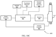
- FIG. 10C is another example of an actuator control in accordance with one aspect of the disclosure.
- the actuator control 600 may include a power source or multiple power sources and/or power supplies 604 which may for example be the battery or in signal communication with battery 110 ( FIG. 3 ) and/or a battery within or connected to the interchangeable passenger portion, for example.
- the actuator control may further include a single sensor or multiple sensors configured to output a signal indicative of the extension/retraction of actuator 603 .
- the sensor 601 may include limit switches similar to limit switches 400 a and 400 b ( FIG. 10A ).
- the sensor 501 may include a single or plurality of optical sensor(s), potentiometer(s) and/or any sensor capable of outputting a signal indicative of the extension and/or retraction of the actuator 603 .
- the actuator control 605 may further include an actuator controller, which may for example be an motor controller if the actuator uses an electric motor and/or electric valves for control of hydraulic fluid and/or fluid flow/pressure if the actuator 603 is hydraulic and or pneumatically operated.
- the system my further include in interface 602 , which may for example be a switch, a series of switches, and/or an interface for displaying information and/or providing a user with a control interface for controlling movement of the actuator 603 .
- the system may further comprise a touchdown sensor or sensors 631 (e.g., touchdown detection portion 231 ), which may provide a signal to the controller that the footrest platform 206 is close to or in contact with an object or the ground.
- the controller may prevent further movement of the linear actuator in a direction corresponding to the downward direction of the footrest platform 206 .
- the controller may prevent further movement of the footrest in the upward direction if an output from the footrest position sensor or sensors 630 (e.g., first and/or second footrest detection portions), provide a signal indicative of an object or foreign object between the footrest platform 206 and the seat portion 201 .
- the controller may again allow movement of any of the aforementioned components once it is determined that no interference would occur between components during the movement of footrest platform 206 .
- one or more microcontrollers may be implemented for carrying out certain features of the present disclosure, such as control features for controlling the actuator system 300 and/or 500 of FIGS. 9A-9B .
- An example of such a microcontroller 1100 is shown in FIG. 11 .
- the microcontroller 1100 includes a CPU 1102 , RAM 1108 , ROM 1110 , a timer 1112 , a BUS controller 1114 , an interface 1116 , and an analog-to-digital converter (ADC) 1118 interconnected via an on board BUS 1106 .
- ADC analog-to-digital converter
- the CPU 1102 may be implemented as one or more single core or multi-core processors, and receive signals from an interrupt controller 1120 and a clock 1104 .
- the clock 1104 sets the operating frequency of the entire microcontroller 1100 and may include one or more crystal oscillators having predetermined frequencies. Alternatively, the clock 1104 may receive an external clock signal.
- the interrupt controller 1120 may also send interrupt signals to the CPU to suspend CPU operations.
- the interrupt controller 1120 may transmit an interrupt signal to the CPU when an event requires immediate CPU attention.
- the RAM 1108 may include one or more SRAM, DRAM, SDRAM, DDR SDRAM, DRRAM or other suitable volatile memory.
- the ROM 1110 may include one or more PROM, EPROM, EEPROM, flash memory, or other types of non-volatile memory.
- the timer 1112 may keep time and/or calculate the amount of time between events occurring within the microcontroller 1100 , count the number of events, and/or generate baud rate for communication transfer.
- the BUS controller 1114 prioritizes BUS usage within the microcontroller 1100 .
- the ADC 1118 allows the microcontroller 1100 to send out pulses to signal other devices.
- the interface 1116 is an input/output device that allows the microcontroller 1100 to exchange information with other devices.
- the interface 1116 may include one or more parallel port, a serial port, or other computer interfaces.
- example is used herein to mean “serving as an example, instance, or illustration.” Any aspect described herein as “example” is not necessarily to be construed as preferred or advantageous over other aspects. Unless specifically stated otherwise, the term “some” refers to one or more.
- Combinations such as “at least one of A, B, or C,” “at least one of A, B, and C,” and “A, B, C, or any combination thereof” include any combination of A, B, and/or C, and may include multiples of A, multiples of B, or multiples of C.
- combinations such as “at least one of A, B, or C,” “at least one of A, B, and C,” and “A, B, C, or any combination thereof” may be A only, B only, C only, A and B, A and C, B and C, or A and B and C, where any such combinations may contain one or more member or members of A, B, or C.
Landscapes
- Engineering & Computer Science (AREA)
- Mechanical Engineering (AREA)
- Transportation (AREA)
- Passenger Equipment (AREA)
Abstract
Description
| Number | Part Names | ||
| 50a, b, c | wheels | ||
| 70a, b | cargo/passenger carrying portion | ||
| 68a | cargo area | ||
| 68b | passenger carrying portion seat | ||
| 100 | vehicle | ||
| 101 | vehicle frame | ||
| 102a, b | pedals | ||
| 103 | steering tube | ||
| 104a, b | cranks | ||
| 105 | sprocket | ||
| 106 | U-shaped portion | ||
| 109 | motor | ||
| 110 | battery | ||
| 112a, b | front hubs | ||
| 114a, b | knuckles | ||
| 115a, b | arms | ||
| 116a, b | brake disks | ||
| 118a-c | brake calibers | ||
| 119a, b | tie rods | ||
| 120 | handlebar | ||
| 123 | handlebar mount | ||
| 127 | seat | ||
| 128 | seat post | ||
| 129 | seat tube | ||
| 131a, b | side mounts | ||
| 200 | passenger carrying portion | ||
| 201 | seat portion | ||
| 203 | moveable footrest | ||
| 204 | seat centering feature | ||
| 205 | footrest centering feature | ||
| 206 | footrest platform | ||
| 208 | footrest platform frame | ||
| 210 | backrest | ||
| 211a, b | rear mounting portions | ||
| 212 | seat surface | ||
| 214a-c | gussets | ||
| 215 | first cross-member | ||
| 216 | second cross-member | ||
| 217a, b | mounting frames | ||
| 218, 219 | footrest movement mechanisms | ||
| 220a, b | mounting portions | ||
| 229 | first footrest detection portion | ||
| 230 | second footrest detection portion | ||
| 231 | touchdown detection portion | ||
| 255a, b | T racks | ||
| 300 | touchdown sensor array | ||
| 302 | actuator | ||
| 311a, b, c | detectors | ||
| 322a, b | biasing members | ||
| 303 | controller | ||
| 400a, b | limit switches | ||
| 402 | actuator | ||
| 403 | switch | ||
| 404 | power source | ||
| 500 | actuator control | ||
| 501 | sensor | ||
| 502 | interface | ||
| 504 | power supplies | ||
| 600 | actuator control | ||
| 601 | sensor | ||
| 602 | interface | ||
| 604 | power supplies | ||
| 630 | footrest position sensor | ||
| 631 | touchdown sensor | ||
| 1100 | microcontroller | ||
| 1102 | cpu | ||
| 1104 | clock | ||
| 1106 | board bus | ||
| 1108 | ram | ||
| 1110 | rom | ||
| 1112 | timer | ||
| 1114 | bus controller | ||
| 1116 | interface | ||
| 1118 | adc | ||
| 1120 | controller | ||
Claims (19)
Priority Applications (1)
| Application Number | Priority Date | Filing Date | Title |
|---|---|---|---|
| US16/370,531 US11260784B2 (en) | 2019-03-29 | 2019-03-29 | Active vehicle footrest |
Applications Claiming Priority (1)
| Application Number | Priority Date | Filing Date | Title |
|---|---|---|---|
| US16/370,531 US11260784B2 (en) | 2019-03-29 | 2019-03-29 | Active vehicle footrest |
Publications (2)
| Publication Number | Publication Date |
|---|---|
| US20200307434A1 US20200307434A1 (en) | 2020-10-01 |
| US11260784B2 true US11260784B2 (en) | 2022-03-01 |
Family
ID=72607757
Family Applications (1)
| Application Number | Title | Priority Date | Filing Date |
|---|---|---|---|
| US16/370,531 Active 2039-12-11 US11260784B2 (en) | 2019-03-29 | 2019-03-29 | Active vehicle footrest |
Country Status (1)
| Country | Link |
|---|---|
| US (1) | US11260784B2 (en) |
Citations (15)
| Publication number | Priority date | Publication date | Assignee | Title |
|---|---|---|---|---|
| US3350065A (en) | 1966-10-24 | 1967-10-31 | Standard Mfg Company Inc | Scissor-type linear actuator with high extension ratio and selectable extension rateand power requirement |
| US4858481A (en) | 1985-05-13 | 1989-08-22 | Brunswick Valve & Control, Inc. | Position controlled linear actuator |
| US5557154A (en) | 1991-10-11 | 1996-09-17 | Exlar Corporation | Linear actuator with feedback position sensor device |
| GB2414172A (en) | 2004-05-21 | 2005-11-23 | Helping Hand Co Ledbury | Footrest raising mechanism for a chair |
| EP2062567A1 (en) | 2006-09-08 | 2009-05-27 | Kao Corporation | Skin or hair cleanser composition |
| US20110049945A1 (en) | 2009-08-28 | 2011-03-03 | Shimano Inc. | Motorized bicycle seatpost assembly |
| US8249773B2 (en) | 2008-11-27 | 2012-08-21 | Toyota Jidosha Kabushiki Kaisha | Vehicle and its control method |
| JP5065778B2 (en) | 2006-09-13 | 2012-11-07 | 株式会社松永製作所 | Wheelchair footrest mechanism |
| EP2833850A1 (en) | 2012-04-05 | 2015-02-11 | 4 Power 4 SPRL | Foot-rest for a wheelchair |
| US20150151804A1 (en) | 2011-08-24 | 2015-06-04 | Trek Bicycle Corp. | Automatic drop seatpost |
| US20150190292A1 (en) | 2014-01-08 | 2015-07-09 | Douglas G. Robins | Wheelchair |
| US20170361893A1 (en) * | 2014-11-13 | 2017-12-21 | Chunghsin Lee | Power assisted foldable bicycle |
| CN107802424A (en) | 2017-11-17 | 2018-03-16 | 南京康尼机电股份有限公司 | A kind of wheelchair pedal device and the section bar on wheelchair pedal |
| US20180110664A1 (en) * | 2015-04-14 | 2018-04-26 | Jaimie Borisoff | Kneeling Wheelchair Frame |
| US20190275920A1 (en) * | 2017-04-28 | 2019-09-12 | Jong Hoon Bae | Assembled footrest of car seat apparatus for early child |
-
2019
- 2019-03-29 US US16/370,531 patent/US11260784B2/en active Active
Patent Citations (15)
| Publication number | Priority date | Publication date | Assignee | Title |
|---|---|---|---|---|
| US3350065A (en) | 1966-10-24 | 1967-10-31 | Standard Mfg Company Inc | Scissor-type linear actuator with high extension ratio and selectable extension rateand power requirement |
| US4858481A (en) | 1985-05-13 | 1989-08-22 | Brunswick Valve & Control, Inc. | Position controlled linear actuator |
| US5557154A (en) | 1991-10-11 | 1996-09-17 | Exlar Corporation | Linear actuator with feedback position sensor device |
| GB2414172A (en) | 2004-05-21 | 2005-11-23 | Helping Hand Co Ledbury | Footrest raising mechanism for a chair |
| EP2062567A1 (en) | 2006-09-08 | 2009-05-27 | Kao Corporation | Skin or hair cleanser composition |
| JP5065778B2 (en) | 2006-09-13 | 2012-11-07 | 株式会社松永製作所 | Wheelchair footrest mechanism |
| US8249773B2 (en) | 2008-11-27 | 2012-08-21 | Toyota Jidosha Kabushiki Kaisha | Vehicle and its control method |
| US20110049945A1 (en) | 2009-08-28 | 2011-03-03 | Shimano Inc. | Motorized bicycle seatpost assembly |
| US20150151804A1 (en) | 2011-08-24 | 2015-06-04 | Trek Bicycle Corp. | Automatic drop seatpost |
| EP2833850A1 (en) | 2012-04-05 | 2015-02-11 | 4 Power 4 SPRL | Foot-rest for a wheelchair |
| US20150190292A1 (en) | 2014-01-08 | 2015-07-09 | Douglas G. Robins | Wheelchair |
| US20170361893A1 (en) * | 2014-11-13 | 2017-12-21 | Chunghsin Lee | Power assisted foldable bicycle |
| US20180110664A1 (en) * | 2015-04-14 | 2018-04-26 | Jaimie Borisoff | Kneeling Wheelchair Frame |
| US20190275920A1 (en) * | 2017-04-28 | 2019-09-12 | Jong Hoon Bae | Assembled footrest of car seat apparatus for early child |
| CN107802424A (en) | 2017-11-17 | 2018-03-16 | 南京康尼机电股份有限公司 | A kind of wheelchair pedal device and the section bar on wheelchair pedal |
Also Published As
| Publication number | Publication date |
|---|---|
| US20200307434A1 (en) | 2020-10-01 |
Similar Documents
| Publication | Publication Date | Title |
|---|---|---|
| US9284015B2 (en) | Folding pedal mount | |
| US9359036B2 (en) | Folding bicycle | |
| US9290229B2 (en) | Bicycle chain stay coupling | |
| US6290014B1 (en) | Power assist for bicycles | |
| US20110185803A1 (en) | Bicycle fitting apparatus and method | |
| US9150272B1 (en) | Folding bicycle chain stay and frame | |
| JP4599907B2 (en) | Traveling device | |
| US9346514B2 (en) | Folding handlebar mount | |
| EP4405239B1 (en) | A compact ground vehicle with electric propulsion | |
| JP2025537953A (en) | Wheeled luggage items with integrated personal mobility capabilities | |
| US11214328B2 (en) | Vehicle steering system | |
| US20060048534A1 (en) | Self propelled food & beverage receptacle | |
| US11260784B2 (en) | Active vehicle footrest | |
| US10501139B2 (en) | Wheelchair accessible cycle | |
| CN214713091U (en) | Back-push type tri-star wheel stair climbing vehicle capable of automatically adjusting seat surface to be horizontal | |
| US20210046993A1 (en) | Pedal-powered wheelchair | |
| DE4006095A1 (en) | Foldable, adjustable bicycle - has short wheel base pedals and transmission above steerable front wheel | |
| JP2002191642A (en) | Wheelchair | |
| KR20180051431A (en) | Lock function joints and strollers for carts | |
| JP2006062526A (en) | Recumbent type bicycle | |
| CN107021125A (en) | Perambulator | |
| JP7309525B2 (en) | Wheel device and vehicle | |
| KR101734573B1 (en) | Steering control system for mobile using movement of upper body | |
| CN121712687A (en) | Cargo attachment | |
| GB2528782A (en) | Folding pedal mount |
Legal Events
| Date | Code | Title | Description |
|---|---|---|---|
| FEPP | Fee payment procedure |
Free format text: ENTITY STATUS SET TO UNDISCOUNTED (ORIGINAL EVENT CODE: BIG.); ENTITY STATUS OF PATENT OWNER: LARGE ENTITY |
|
| AS | Assignment |
Owner name: HONDA MOTOR CO., LTD., JAPAN Free format text: ASSIGNMENT OF ASSIGNORS INTEREST;ASSIGNORS:STAAL, MATTHEW B.;VANWAGONER, NELSON;MOSS, JONATHAN G.;AND OTHERS;REEL/FRAME:048758/0359 Effective date: 20190326 |
|
| STPP | Information on status: patent application and granting procedure in general |
Free format text: NON FINAL ACTION MAILED |
|
| STPP | Information on status: patent application and granting procedure in general |
Free format text: NON FINAL ACTION MAILED |
|
| STPP | Information on status: patent application and granting procedure in general |
Free format text: RESPONSE TO NON-FINAL OFFICE ACTION ENTERED AND FORWARDED TO EXAMINER |
|
| STPP | Information on status: patent application and granting procedure in general |
Free format text: NOTICE OF ALLOWANCE MAILED -- APPLICATION RECEIVED IN OFFICE OF PUBLICATIONS |
|
| STCF | Information on status: patent grant |
Free format text: PATENTED CASE |
|
| MAFP | Maintenance fee payment |
Free format text: PAYMENT OF MAINTENANCE FEE, 4TH YEAR, LARGE ENTITY (ORIGINAL EVENT CODE: M1551); ENTITY STATUS OF PATENT OWNER: LARGE ENTITY Year of fee payment: 4 |