US11259810B2 - Device, assembly and method for use in tendon repair - Google Patents
Device, assembly and method for use in tendon repair Download PDFInfo
- Publication number
- US11259810B2 US11259810B2 US16/401,929 US201916401929A US11259810B2 US 11259810 B2 US11259810 B2 US 11259810B2 US 201916401929 A US201916401929 A US 201916401929A US 11259810 B2 US11259810 B2 US 11259810B2
- Authority
- US
- United States
- Prior art keywords
- tendon
- liner
- sheath
- assembly
- needle
- Prior art date
- Legal status (The legal status is an assumption and is not a legal conclusion. Google has not performed a legal analysis and makes no representation as to the accuracy of the status listed.)
- Active, expires
Links
- 0 *CC1C(C2C(C3)C3C2)C=CC1 Chemical compound *CC1C(C2C(C3)C3C2)C=CC1 0.000 description 2
Images


Classifications
-
- A—HUMAN NECESSITIES
- A61—MEDICAL OR VETERINARY SCIENCE; HYGIENE
- A61B—DIAGNOSIS; SURGERY; IDENTIFICATION
- A61B17/00—Surgical instruments, devices or methods, e.g. tourniquets
- A61B17/04—Surgical instruments, devices or methods, e.g. tourniquets for suturing wounds; Holders or packages for needles or suture materials
- A61B17/0493—Protective devices for suturing, i.e. for protecting the patient's organs or the operator
-
- A—HUMAN NECESSITIES
- A61—MEDICAL OR VETERINARY SCIENCE; HYGIENE
- A61B—DIAGNOSIS; SURGERY; IDENTIFICATION
- A61B17/00—Surgical instruments, devices or methods, e.g. tourniquets
- A61B17/04—Surgical instruments, devices or methods, e.g. tourniquets for suturing wounds; Holders or packages for needles or suture materials
- A61B17/0482—Needle or suture guides
-
- A—HUMAN NECESSITIES
- A61—MEDICAL OR VETERINARY SCIENCE; HYGIENE
- A61B—DIAGNOSIS; SURGERY; IDENTIFICATION
- A61B17/00—Surgical instruments, devices or methods, e.g. tourniquets
- A61B17/04—Surgical instruments, devices or methods, e.g. tourniquets for suturing wounds; Holders or packages for needles or suture materials
- A61B17/06—Needles ; Sutures; Needle-suture combinations; Holders or packages for needles or suture materials
- A61B17/06066—Needles, e.g. needle tip configurations
-
- A—HUMAN NECESSITIES
- A61—MEDICAL OR VETERINARY SCIENCE; HYGIENE
- A61B—DIAGNOSIS; SURGERY; IDENTIFICATION
- A61B17/00—Surgical instruments, devices or methods, e.g. tourniquets
- A61B17/11—Surgical instruments, devices or methods, e.g. tourniquets for performing anastomosis; Buttons for anastomosis
- A61B17/1146—Surgical instruments, devices or methods, e.g. tourniquets for performing anastomosis; Buttons for anastomosis of tendons
-
- A—HUMAN NECESSITIES
- A61—MEDICAL OR VETERINARY SCIENCE; HYGIENE
- A61B—DIAGNOSIS; SURGERY; IDENTIFICATION
- A61B17/00—Surgical instruments, devices or methods, e.g. tourniquets
- A61B17/00234—Surgical instruments, devices or methods, e.g. tourniquets for minimally invasive surgery
- A61B2017/00292—Surgical instruments, devices or methods, e.g. tourniquets for minimally invasive surgery mounted on or guided by flexible, e.g. catheter-like, means
- A61B2017/00336—Surgical instruments, devices or methods, e.g. tourniquets for minimally invasive surgery mounted on or guided by flexible, e.g. catheter-like, means with a protective sleeve, e.g. retractable or slidable
-
- A—HUMAN NECESSITIES
- A61—MEDICAL OR VETERINARY SCIENCE; HYGIENE
- A61B—DIAGNOSIS; SURGERY; IDENTIFICATION
- A61B17/00—Surgical instruments, devices or methods, e.g. tourniquets
- A61B2017/00831—Material properties
- A61B2017/00862—Material properties elastic or resilient
-
- A—HUMAN NECESSITIES
- A61—MEDICAL OR VETERINARY SCIENCE; HYGIENE
- A61B—DIAGNOSIS; SURGERY; IDENTIFICATION
- A61B17/00—Surgical instruments, devices or methods, e.g. tourniquets
- A61B2017/00831—Material properties
- A61B2017/00946—Material properties malleable
-
- A—HUMAN NECESSITIES
- A61—MEDICAL OR VETERINARY SCIENCE; HYGIENE
- A61B—DIAGNOSIS; SURGERY; IDENTIFICATION
- A61B17/00—Surgical instruments, devices or methods, e.g. tourniquets
- A61B17/04—Surgical instruments, devices or methods, e.g. tourniquets for suturing wounds; Holders or packages for needles or suture materials
- A61B17/0401—Suture anchors, buttons or pledgets, i.e. means for attaching sutures to bone, cartilage or soft tissue; Instruments for applying or removing suture anchors
- A61B2017/0464—Suture anchors, buttons or pledgets, i.e. means for attaching sutures to bone, cartilage or soft tissue; Instruments for applying or removing suture anchors for soft tissue
-
- A—HUMAN NECESSITIES
- A61—MEDICAL OR VETERINARY SCIENCE; HYGIENE
- A61B—DIAGNOSIS; SURGERY; IDENTIFICATION
- A61B17/00—Surgical instruments, devices or methods, e.g. tourniquets
- A61B17/04—Surgical instruments, devices or methods, e.g. tourniquets for suturing wounds; Holders or packages for needles or suture materials
- A61B17/06—Needles ; Sutures; Needle-suture combinations; Holders or packages for needles or suture materials
- A61B2017/06052—Needle-suture combinations in which a suture is extending inside a hollow tubular needle, e.g. over the entire length of the needle
-
- A—HUMAN NECESSITIES
- A61—MEDICAL OR VETERINARY SCIENCE; HYGIENE
- A61B—DIAGNOSIS; SURGERY; IDENTIFICATION
- A61B17/00—Surgical instruments, devices or methods, e.g. tourniquets
- A61B17/04—Surgical instruments, devices or methods, e.g. tourniquets for suturing wounds; Holders or packages for needles or suture materials
- A61B17/06—Needles ; Sutures; Needle-suture combinations; Holders or packages for needles or suture materials
- A61B17/06066—Needles, e.g. needle tip configurations
- A61B2017/0608—J-shaped
-
- A—HUMAN NECESSITIES
- A61—MEDICAL OR VETERINARY SCIENCE; HYGIENE
- A61B—DIAGNOSIS; SURGERY; IDENTIFICATION
- A61B17/00—Surgical instruments, devices or methods, e.g. tourniquets
- A61B17/04—Surgical instruments, devices or methods, e.g. tourniquets for suturing wounds; Holders or packages for needles or suture materials
- A61B17/06—Needles ; Sutures; Needle-suture combinations; Holders or packages for needles or suture materials
- A61B17/06066—Needles, e.g. needle tip configurations
- A61B2017/06085—Needles, e.g. needle tip configurations having a blunt tip
-
- A—HUMAN NECESSITIES
- A61—MEDICAL OR VETERINARY SCIENCE; HYGIENE
- A61B—DIAGNOSIS; SURGERY; IDENTIFICATION
- A61B17/00—Surgical instruments, devices or methods, e.g. tourniquets
- A61B17/04—Surgical instruments, devices or methods, e.g. tourniquets for suturing wounds; Holders or packages for needles or suture materials
- A61B17/06—Needles ; Sutures; Needle-suture combinations; Holders or packages for needles or suture materials
- A61B17/06066—Needles, e.g. needle tip configurations
- A61B2017/06095—Needles, e.g. needle tip configurations pliable
-
- A—HUMAN NECESSITIES
- A61—MEDICAL OR VETERINARY SCIENCE; HYGIENE
- A61B—DIAGNOSIS; SURGERY; IDENTIFICATION
- A61B17/00—Surgical instruments, devices or methods, e.g. tourniquets
- A61B17/11—Surgical instruments, devices or methods, e.g. tourniquets for performing anastomosis; Buttons for anastomosis
- A61B2017/1132—End-to-end connections
-
- A—HUMAN NECESSITIES
- A61—MEDICAL OR VETERINARY SCIENCE; HYGIENE
- A61B—DIAGNOSIS; SURGERY; IDENTIFICATION
- A61B90/00—Instruments, implements or accessories specially adapted for surgery or diagnosis and not covered by any of the groups A61B1/00 - A61B50/00, e.g. for luxation treatment or for protecting wound edges
- A61B90/08—Accessories or related features not otherwise provided for
- A61B2090/0801—Prevention of accidental cutting or pricking
- A61B2090/08021—Prevention of accidental cutting or pricking of the patient or his organs
-
- A—HUMAN NECESSITIES
- A61—MEDICAL OR VETERINARY SCIENCE; HYGIENE
- A61B—DIAGNOSIS; SURGERY; IDENTIFICATION
- A61B90/00—Instruments, implements or accessories specially adapted for surgery or diagnosis and not covered by any of the groups A61B1/00 - A61B50/00, e.g. for luxation treatment or for protecting wound edges
- A61B90/08—Accessories or related features not otherwise provided for
- A61B2090/0815—Implantable devices for insertion in between organs or other soft tissues
Definitions
- the present invention relates to a needle covering and carrying device for covering a needle and carrying the needle within a tendon sheath.
- the present invention also relates to an assembly for use in repairing a severed tendon, the assembly comprising a needle and the needle covering and carrying device, and a method of repairing a severed tendon.
- Flexor and extension tendons in the hand extend through tendon sheaths, within which the tendons are movable as the hand is flexed. Injuries to the hand of a human being often result in tendon damage, frequently involving severing of one or more of the tendons.
- Zone 1 comprises the flexor digitorum profundus (FDP) tendon distal to insertion of the flexor digitorum superficialis (FDS) tendon.
- Zone 2 (“no man's land”) comprises insertion of the FDS tendon to the proximal edge of the A1 pulley, which pulley is a cruciform structure beneath which the tendon sits.
- Zone 3 is in the palm, and comprises the proximal edge of the A1 pulley to the distal edge of the carpal tunnel.
- Flexor tendon repair in zone 2 requires an atraumatic tendon retrieval technique with meticulous handling of the tendon stumps and minimal damage to the surrounding tendon sheath, because of the problematic nature of tendon healing without adhesions in this zone.
- Hettiaratchy and Titley described placing a core suture in the tendon stump and using an aneurysm needle to thread the suture through the pulleys, pulling the tendon out with the suture.
- This technique may not suitable to use for tendons retracted into the palm, and requires additional windowing of the sheath, which results in additional damage.
- the surgical repair is performed with atraumatic handling of the severed tendon stumps and minimal damage to the tendon sheath, in order to prevent postoperative adhesions and ruptures in this area. Accordingly, it is extremely desirable to be able to draw the tendon through its sheath with a ‘needled’ suture that can be continued as part of the definitive repair.
- Bhatti & Adeniran (2006) [10] described a technique of suturing the proximal tendon stump at the distal palmar crease with a straight needle and polypropylene suture, and using a 14-gauge plastic cannula with stylet, acting like a conduit for the passage of the straight needle to the finger. Traction of the suture end results in delivery of the cut tendon stump.
- the straight needle is not always available in the operating room. More important to note is that it is difficult to complete a modified Kessler stitch using a straight needle, or many of the other popular tendon suture techniques, which use curved needles.
- Ozturk et al. (2013) present a simple and relatively atraumatic technique that facilitates passing of the retracted flexor tendon through the pulleys in zone 2.
- the authors sutured the proximal tendon stump at the distal palmar crease with a 3-0 polypropylene suture, and used a 14-gauge plastic feeding tube, acting like a conduit for the passage of a straightened needle to the finger.
- US Patent Publication No. US-2013/0144310A1 discloses an apparatus for reattaching severed tendon stumps in the hand.
- the disclosed apparatus (see FIG. 1 ) is complex and comprises numerous components including a pulley catheter which is connected to a flanged catheter by a connector.
- the pulley catheter is of a polymeric material with sufficient rigidity (so that it can be pushed through tendon pulleys), and the flanged catheter is of a softer polymeric material such as a silicone.
- the apparatus also comprises a tendon anchor including a short straight needle which is attached to an end of a multifilament cable, the cable being unwound into separate sutures from a sleeve located at an intermediate point of the cable.
- Curved needles are attached to the end of each suture.
- the pulley catheter is fed into an incision in the palm and along a tendon sheath beneath tendon pulleys (see FIG. 2 A).
- the flanged catheter is then connected to the pulley catheter and drawn part-way into the tendon sheath (see FIG. 2B ).
- a tendon stump in the palm is then delivered to the surface and the straight needle of the tendon anchor placed into and pulled through the stump.
- the curved needles are then used to stich the tendon repair device to the stump, a pair of sutures being tied in a knot and stitched to the tendon using criss-cross locking stiches formed using further curved needles and sutures. Excess suture material and the curved needles are then removed (see FIGS. 2D &E).
- the straight needle is then inserted into the flange of the flanged catheter and advanced until the tendon stump is in the flanged portion. The surgeon then grasps the straight needle and pulls the needle, attached cable, flanged catheter and tendon stump through the pulley system and out of a wound in the finger.
- a further tendon anchor of a similar structure is then attached to the tendon stump in the finger in the same way as described above, and the needles of the two anchors inserted through bores of a connector, passing in opposite directions. Traction is then applied to the tendon stumps to pull them together with the connector buried in the tendon ends. A crimping tool is then used to crimp the connector and extra lengths of the cables are cut.
- An apparatus like the pulley catheter is also disclosed, and is described as a dilation catheter which has a wall thickness sufficient to make the entire catheter sufficiently stiff to be pushed through the pulley system, and to serve the purpose of dilating the pulleys against their natural size.
- the apparatus disclosed in US-2013/0144310A1 is complex and the procedure for tendon repair described is cumbersome.
- the system suffers from numerous disadvantages. These include that the tendon anchor is complex to assemble, and its use in a surgical procedure is complicated and time-consuming. Manipulating the straight needle and trailing cable to insert it through the tendon stumps is challenging, and requires the use of various clamps to hold the tendon stumps in place. Advancing the tendon anchor along the flanged catheter is also challenging, since it is necessary to use the cable connected to the needle to advance it through the catheter. Furthermore, it is difficult to make the cable sufficiently rigid to achieve this without hampering the procedure for connecting the tendon anchor to the stumps.
- the pulley catheters are typically 120 mm long, of relatively small outer diameter (typically 2 mm), with a wall thickness of 0.5 mm thus having an internal diameter of 1 mm (see para. 0070). It would be difficult to push the straight needle through a pulley catheter of the above dimensions with a cable.
- the sleeves of the tendon anchors, and the connector that is used to connect the cables of the two anchors, are all buried within the tendon stumps.
- a needle covering and carrying device for covering a curved needle and carrying the needle within a lumen of a tendon sheath, the device comprising an elongate element having:
- Surgical techniques for the repair of damaged tendons would greatly benefit from the use of a curved needle.
- use of a curved needle improves the ability of a surgeon to suture stumps of a severed tendon together.
- the present application discloses embodiments that facilitate the passage of a curved needed within a tendon sheath whilst restricting, or even avoiding, damage to the sheath through contact with the needle.
- the needle can be drawn through the tendon sheath trailing a tendon stump, so that the stump can be sutured to the stump of a second portion of the tendon.
- the second portion of tendon may reside in the finger.
- a needle covering and carrying device for covering a curved needle and carrying the needle within a tendon sheath.
- the tendon sheath may be one of many different sheaths, ducts or conduits found in the human (or animal) body.
- disclosed embodiments have a particular use in relation to surgery on the hand, in which the tendon sheath will be the sheath of a tendon found in the hand (e.g. the FDP or FDS tendon).
- the device in particular the cavity, may be adapted to receive the entire needle.
- the device may form an envelope or shroud for the needle.
- the cavity may extend from the first end of the device to the second end of the device.
- the first end of the body may be a leading end and the second end may be a trailing end. At least one of the first and second ends may be open, or at least partially open, and may communicate with the cavity. This may facilitate insertion of the needle into the cavity through the open end, and/or may allow a suture connected to the needle to exit the body.
- the body may serve for transporting the needle along or within the sheath.
- the first end may be adapted to be inserted into the tendon sheath and directed along it.
- the body may form a threading element (hereinafter called a threader) adapted to transit along the sheath.
- the body may comprise a portion defining the threader and a portion which forms a cover for the needle.
- the threader portion may be substantially straight, which may facilitate transit within the sheath.
- the cover portion may have the curved shape.
- the cover portion may be capable of being deformed into the curved shape.
- the cavity may extend part way along a length of the body.
- the cavity may extend from one of the first and second ends in a direction towards the other one of the first and second ends. Where the second end is a trailing end, the cavity may extend from the second end towards the first end.
- the cavity may be disposed between the first and second ends.
- the body may comprise a coupling for connecting the device to a transportation assembly used to transport the device within the sheath.
- the transportation assembly may comprise an elongate threading element (threader) and a flexible connecting component connected to the threader, the connecting component being adapted to be connected to the coupling of the body.
- the connecting component may be flexible, may be a cord, wire, filament or the like, and may be a suture.
- the coupling may be an eye, hoop or the like mounted on or connected to the body.
- the body may be generally tubular.
- the body may be generally cylindrical, and may have a circular shape in cross-section.
- the device may comprise an outer sheath, sleeve or covering.
- the outer sheath may ease passage of the device within the tendon sheath.
- the outer sheath may be of a plastics (suitably polymeric) or elastomeric material, which materials may have a low coefficient of friction, to facilitate passage of the device within the tendon sheath.
- the outer sheath may have an inner surface which is disposed in contact with an outer surface of the body.
- the outer sheath may be tubular.
- the outer sheath may extend at least part way along a length of the body.
- the outer sheath may extend in a direction from one of the first and second ends of the device in a direction towards the other one of the first and second ends.
- the outer sheath may extend from the first end along the body in a direction towards the second end.
- the outer sheath may cover the first end.
- the second end is a trailing end, the second end may be exposed, and so may not be covered by the outer sheath.
- a portion of the body may define the cavity. The portion may be exposed, and so may not be covered by the outer sheath. The outer sheath may therefore extend from the first end along the body to said portion.
- a needle covering and carrying device according to option A may have one or more of the following features.
- the cavity may be curved.
- the cavity may have a curved shape which substantially matches that of the curved needle.
- the needle may have a radius of curvature, and the cavity may have a radius of curvature.
- the radius of curvature of the cavity may substantially match that of the needle.
- the body may comprise a first body part, and a second body part which is connected to the first body part.
- the first and second body parts when connected, may form the body.
- At least one of the first and second body parts may be movable relative to the other one of the first and second body parts, and may be movable between an open position in which the needle can be inserted into the cavity, and a closed position in which the cavity is closed.
- the body may be lockable in the closed position.
- the device may comprise a clip, clamp or lock for locking the body in the closed position.
- At least one of the first and second body parts may be pivotable relative to the other one of the first and second body parts, such as via a hinge.
- the hinge may be a living hinge.
- Suitable materials for the body may be selected from the group comprising: plastics, suitably polymeric materials; metals; and metal alloys.
- a needle covering and carrying device according to option B may have one or more of the following features.
- At least part of the body of the device may be plastically deformable.
- a part of the body defining the cavity may be plastically deformable.
- the entire body may be plastically deformable.
- the device may be capable of being bent into a required shape (to accommodate the curved needle), which may occur either on insertion of the needle into the cavity, or in advance such as by appropriate manipulation of the body to have a shape which suits a particular needle.
- At least part of the body of the device may be elastically deformable.
- a part of the body defining the cavity may be elastically deformable.
- the entire body may be elastically deformable.
- the device may be capable of adopting a curved shape when the needle is inserted into the cavity.
- the body may be elastically deformable from an undeformed or starting configuration, which may be a substantially straight and/or unstressed configuration, to a deformed or deployed configuration, which may be a curved configuration.
- the body may return to the undeformed configuration when the needle is removed from the cavity.
- the body may be of a metal or metal alloy material.
- the body may take the form of a spring.
- the spring may be a tension spring or sprung member.
- the spring may be helically wound.
- the spring may comprise a plurality of turns or coils, which may be arranged so that the turns or coils are in abutment (which may be close abutment), at least in a rest state.
- the spring may be of a metal or metal alloy material, such as a stainless steel material, although plastics (suitably polymeric) materials may be suitable.
- the body particularly where it takes the form of a spring, may be deformable in multiple directions, relative to a main axis of the body (in an undeformed state). The body may therefore be deflectable in any desired direction away from the main axis (for example a radial direction). The body may therefore demonstrate a high degree of compliance.
- the body may comprise a sidewall.
- An opening may be formed in the sidewall which communicates with the cavity.
- the needle may be insertable into the cavity through the opening.
- an assembly for use in repairing a severed tendon comprising:
- an assembly for use in repairing a severed tendon comprising:
- a threading element which is an element that is adapted, by appropriate shaping (e.g. elongate and of relatively small diameter or width) and/or selection of materials (e.g. plastically deformable/malleable or elastically deformable), to pass along the narrow lumen of the tendon sheath, and so to transit the sheath trailing the liner.
- appropriate shaping e.g. elongate and of relatively small diameter or width
- materials e.g. plastically deformable/malleable or elastically deformable
- the threading element may serve for drawing the liner into the lumen of the tendon sheath, and may then be released from the liner so that the liner can be disposed within the lumen, in which position the liner may serve to restrict (and optionally to entirely prevent) contact between the tendon stump and the internal surface of the tendon sheath. This may restrict (and potentially avoid) damage to the tendon stump during transit along the lumen, which could otherwise fray, making it difficult to subsequently connect it to a further stump of the tendon in a tendon repair procedure of the type described above.
- the liner has a particular use in restricting contact between a tendon stump and the internal surface of the tendon sheath (and optionally preventing contact), the liner may also serve for restricting (and potentially avoiding) contact between other objects and the internal surface of the tendon sheath, including but not restricted to the threading element itself, for example during return transit along the lumen.
- the assembly may comprise a needle covering and carrying device for covering a curved needle and carrying the needle within the lumen of a tendon sheath.
- the needle covering and carrying device may comprise an elongate element having:
- the body may be deformable, and capable of being deformed into a curved shape so that it can accommodate the curved needle.
- the body may be substantially rigid, having a curved shape so that it can accommodate the curved needle.
- the body may form the threading element.
- the body may comprise a portion defining the threading element and a portion which forms a cover for the needle.
- the liner may be elongate.
- the liner may take the form of a sheath.
- the liner may be substantially tubular, and may have any suitable cross-sectional shape.
- the liner may be collapsible and/or adapted to be flattened for easy insertion into and transit along the lumen of the tendon sheath. This may be achieved by selection of suitable materials for the liner, and the provision of a liner having a wall thickness which is suitable for collapsing/flattening.
- the liner may comprise an outer surface adapted to contact the internal surface of the tendon sheath, and an inner surface which defines the internal passage, and which may be contacted by the tendon stump during transit along the lumen.
- the liner may comprise a slit, and may be slit along an entire length of the liner from a first axial end to a second axial end.
- the provision of a liner having such a slit may facilitate removal of the liner from the lumen following completion of a tendon repair procedure in which tendon stumps are connected to restore function to a severed tendon, the slit enabling the liner to be drawn over the repaired tendon leaving the tendon in place within the lumen of the tendon sheath.
- the liner may be adapted to be rolled or coiled, for example about a longitudinal axis, so as to define the internal passage. Rolling or coiling of the liner may form it into the shape of a tube.
- the liner may comprise a first lateral edge and a second lateral edge. Where the liner is rolled or coiled, a portion of the liner comprising one of the lateral edges may overlap a portion of the liner comprising the other lateral edge.
- the liner may be of a plastics (suitably polymeric) or elastomeric material, which materials may have a low coefficient of friction, to facilitate insertion into the lumen of the tendon sheath, and transit of the tendon stump along the internal passage of the liner.
- the liner may comprise a sheath lining portion adapted to be located within the lumen of the tendon sheath, and a pulling portion extending from the lumen lining portion and adapted to be used to pull the sheath lining portion into and along the lumen.
- the pulling portion may have a length which greater than, or substantially equal to, a length of the sheath lining portion.
- the threading element may be adapted to be coupled to the pulling portion, and may be used to draw the pulling portion into the lumen.
- the pulling portion may subsequently be used to draw the sheath lining portion into the lumen, by pulling an end of the pulling portion out of the lumen.
- the pulling portion may be adapted to be gripped by a user to pull the sheath lining portion into the lumen.
- the sheath lining portion may be substantially tubular (including where it comprises a slit and is coiled as discussed above).
- the pulling portion may comprise one or more elongate strips, legs or the like, which may extend from the substantially tubular lumen lining portion.
- the pulling portion may also be tubular, and may be of a smaller diameter or width than the lumen-lining portion.
- the pulling portion may be integral with the lumen-lining portion.
- the assembly may comprise at least one further liner, for lining an internal surface of a further tendon sheath.
- the further liner may also be adapted to be releasably coupled to the threading element so that it can be drawn into the further tendon sheath by the threading element and located within the lumen of the further tendon sheath, and then released from the threading element so as to reside within the lumen.
- the further liner may have a use in a tendon repair procedure of a further tendon, for example in the same or in a second (and optionally further) finger.
- the threading element may take the form of a spring.
- the spring may be a tension spring or sprung member.
- the spring may be helically wound.
- the spring may comprise a plurality of turns or coils, which may be arranged so that the turns or coils are in abutment (which may be close abutment), at least in a rest state.
- the spring may be of a metal or metal alloy material, such as a stainless steel material, although plastics (suitably polymeric) materials may be suitable.
- the threading element may comprise an outer sheath, sleeve or covering.
- the outer sheath may ease passage of the threading element within the tendon sheath.
- the outer sheath may be of a plastics (suitably polymeric) or elastomeric material, which materials may have a low coefficient of friction, to facilitate passage of the device within the tendon sheath.
- the outer sheath may have an inner surface which is disposed in contact with an outer surface of the body.
- the body may comprise a portion defining the threading element and a portion which forms a cover for the needle.
- the cover may have the same structure as that of the threading element and may be continuous with it.
- the threading element is formed of a spring as mentioned above (optionally comprising a plurality of coils)
- the outer (covering) sheath may give the threading element a measure of rigidity so it can be pushed through the lumen of the tendon sheath.
- a stiffness or flexural modulus of the part of the threading element covered by the outer sheath may be greater than a part which is not covered by the outer sheath.
- the part of the threading element which is covered by the outer sheath may be stiffer than the part that is not covered.
- the assembly may comprise a flexible connecting component for releasably connecting the threading element to the liner.
- the flexible connecting component may be a cord, wire, filament or the like, and may be a suture.
- the assembly comprises a needle covering and carrying device (in which the body of the device forms the threading element)
- the flexible connecting component may be a suture connected to the needle.
- the needle will be removed from the covering and carrying device before the suture is used to draw the liner into the lumen of the tendon sheath.
- the flexible connecting component may be releasably connected to the threading element by tying, such as by whipping the connecting component to/around the threading element.
- the threading element comprises an outer sheath
- the flexible connecting component may be releasably connected to the threading element by trapping a part of the connecting component between an outer surface of the body and an inner surface of the outer sheath.
- the threading element takes the form of a spring
- the spring may define an internal passage and may have an open end, and the flexible connecting component may pass up the internal passage of the spring to the open end of the spring, before exiting from the open end and passing away from the open end between an outer surface of the spring and an inner surface of the outer sheath.
- the flexible connecting component may be formed into a loop.
- the liner, in particular the pulling portion (for example at least one of the one or more elongate strips) may be folded over the loop, and the flexible connecting component may be secured relative to the liner by tying, such as by whipping the connecting component to/around the liner.
- the liner may be coupled to the threading element so as to define two tendon sheath lining portions.
- the liner may have a first end and a second end, and coupling may be achieved by connecting the liner to the threading element at a point along a length of the liner between the first and second ends, suitably at or proximate a midpoint of the liner. Coupling may be achieved by folding the liner at said point, about/to the threading element or the connecting component.
- a length of each tendon sheath lining portion may be substantially the same, although the lengths could be different, provided that they are sufficiently long to line the tendon sheath (or at least the part of the tendon sheath extending between surgical openings).
- the tendon sheath lining portions may serve for receiving the tendon stumps of respective tendons. It is well known that tendon sheaths in the finger can accommodate more than one tendon. The assembly may therefore enable two tendon sheath lining portions to be located in a single tendon sheath, for use where both of the finger tendons are to be repaired.
- the liner may comprise a first end, a second end, and a body extending between the first and second ends.
- the liner may comprise a first tendon sheath lining portion extending from the first end towards a part of the liner disposed between the first and second ends, and a second tendon sheath lining portion extending from the second end towards the part disposed between the first and second ends.
- the first and second tendon sheath lining portions may each have a width, and said part may have a width which is less than the width of the first and second tendon sheath lining portions.
- a width of the first tendon sheath lining portion may be the same as (or substantially the same as) a width of the second tendon sheath lining portion.
- Said part may comprise a main section of substantially constant width; a first transition section extending between the main section and the first tendon sheath lining portion; and a second transition section extending between the main section and the second tendon sheath lining portion.
- the transition sections may have a width which progressively increases from the width of the main section to the width of the respective tendon sheath lining portion.
- Said part may comprise a first transition section extending from the first tendon sheath lining portion; and a second transition section extending from the second tendon sheath lining portion and coupled to the first transition section.
- the transition sections may have a width which progressively increases from a width defined at or by an intersection between the transition sections, to the width of the respective tendon sheath lining portions.
- the liner may be adapted to be releasably coupled to the threading element (in particular the flexible connecting component) in or at said part.
- the liner may be releasably couplable to the threading element by folding it over the loop at or about said part.
- the first and second tendon sheath lining sections may be adapted to be separated from one another, suitably by severing the liner so as to remove said part.
- a method of retrieving a tendon stump of a severed tendon which may be part of a method of repairing a severed tendon, the method comprising the steps of:
- the method may comprise locating a free end of the suture within the cavity defined by the body. Following removal of the elongate element from the tendon sheath, the method may comprise removing the needle and the end of the suture from the cavity in the body, optionally before drawing the first tendon stump along the tendon sheath.
- the method may comprise passing the curved needle connected to the suture through the second tendon stump, to connect the suture to the second tendon stump; and manipulating the suture to connect the first tendon stump to the second tendon stump, and thereby repair the severed tendon.
- the method may comprise locating the entire needle within the cavity (and so including a trailing end of the needle, which may be coupled to the suture), so that the entire needle is covered by the device.
- the method may comprise removing the first tendon stump from the tendon sheath to expose the stump, and then connecting the suture to the first stump.
- the method may comprise removing the second tendon stump from the tendon sheath to expose the stump, and then connecting the suture to the second stump.
- the method may comprise inserting the entire needle into the cavity in the body of the threader.
- the suture may pass out of the body through an opening, which may be provided in or by the second end.
- the step of removing the device from the tendon sheath may comprise drawing the second end of the device out of the sheath.
- the tendon sheath may comprise a number of sheath parts or portions which together form the sheath. This may particularly be the case in a surgical procedure, in which apertures may be formed in the tendon sheath so that the damaged tendon can be accessed.
- the first tendon stump may be a proximal stump
- the second tendon stump may be a distal stump.
- the distal end may be disposed closer to a tip of a finger containing the tendon.
- the assembly and method may have a use in surgery on other parts of the human or animal body, such as the foot.
- the method may comprise the step of lining an internal surface of the tendon sheath with a liner, the liner defining an internal passage along which the first tendon stump can pass during transit along the tendon sheath.
- the tendon sheath may be lined prior to carrying out the step of locating at least the penetrating tip of the curved needle within the cavity defined by the body, and may be carried out prior to carrying out the step of passing the curved needle trailing the suture through the first tendon stump.
- the liner may be drawn into the tendon sheath by a threading element which can transit along a lumen of the tendon sheath.
- the threading element may be formed by the body of the covering and carrying device.
- the method may comprise releasably coupling the liner to the threading element.
- the liner may be released from the threading element following location within the lumen.
- the step of inserting the first end of the elongate element into the tendon sheath may comprise inserting the first end into the internal passage of the liner.
- the step of directing the elongate element along the tendon sheath carrying the needle and the suture may comprise directing the elongate element along the internal passage of the liner.
- the step of removing the needle covering and carrying device from the tendon sheath may comprise removing the elongate element from the internal passage of the liner.
- the method may comprise the step of removing the liner from the tendon sheath following passing of the curved needle connected to the suture through the second tendon stump.
- the liner may only be removed following manipulation of the suture to connect the first tendon stump to the second tendon stump, and thereby repair the severed tendon.
- the liner may comprise a slit, which may extend along an entire length of the liner from a first axial end to a second axial end, the slit facilitating removal of the liner from the lumen.
- the liner may be removed by sliding it laterally relative to the tendon, so that the tendon passes through or out of the slit.
- the method may comprise the step of lining an internal surface of the tendon sheath with a liner which is coupled to the threading element so as to define two tendon sheath lining portions.
- the liner may have a first end and a second end, and may be coupled to the threading element at a point along a length of the liner between the first and second ends, suitably at or proximate a midpoint of the liner.
- the tendon sheath lining portions may serve for receiving the tendon stumps of respective tendons. The method may therefore be for repairing two severed tendons, which tendons are normally located within a single tendon sheath.
- a method of lining a tendon sheath of a severed tendon in preparation for performing a tendon repair procedure comprising the steps of:
- an assembly for use in repairing a severed tendon comprising:
- the body may be defined by the spring.
- the body may have an outer surface, and the elongate threading element may comprise an outer sleeve having an inner surface which is disposed in contact (optionally close contact) with the outer surface of the body.
- the outer sleeve may extend part way along a length of the body from the first end.
- the outer sleeve may provide a degree of rigidity to the body (without overly restricting its ability to deform to transit along the lumen of the tendon sheath), which may facilitate insertion of the body into the tendon sheath, and pushing of the body along the lumen.
- a portion of the body comprising the second end may be adapted to accommodate the curved needle, and the outer sleeve may extend from the first end to said portion of the body so that said portion is not covered by the outer sleeve. Leaving said portion of the body uncovered by the outer sleeve may provide the portion with greater flexibility than the covered portion of the body, so that it can more easily deform to accommodate the curved needle.
- the liner, in the collapsed configuration may be substantially flat and may be a lay-flat tube.
- the liner, in the collapsed configuration may have a width and a height, the width being greater than the height.
- the width may be significantly greater than the height.
- a ratio of the height to the width may be in the range of from about 1:100 to about 1:10.
- the assembly may comprise a flexible connecting component for releasably connecting the threading element to the liner.
- the flexible connecting component may be formed into a loop which extends from the threading element.
- the liner may be coupled to the threading element by folding the liner over the loop and coupling a folded part of the liner to a main part of the liner.
- the second end of the body may be a trailing end, and the spring may have an open end which defines the second end of the body.
- the spring may define the internal cavity of the body, the flexible connecting component passing into the open end and along the internal cavity.
- the first end of the body may be a leading end, and the spring may have a further open end which defines the first end of the body.
- the flexible connecting element may extend along the internal cavity to the further open end of the spring, exiting the spring from the further open end and passing away from the open end between the outer surface of the spring and the inner surface of the outer sleeve.
- the liner may comprise a sheath lining portion adapted to be located within the lumen of the tendon sheath, and a pulling portion extending from the lumen lining portion and adapted to be used to pull the sheath lining portion into and along the lumen.
- the sheath lining portion may be substantially tubular, and the pulling portion may comprise one or more leg which extends from the sheath lining portion.
- the spring may be generally tubular, and may be a helically wound spring.
- a kit may be provided comprising the assembly of the third or sixth aspects of the present disclosure and at least one further liner, which may be of the type defined above.
- the further liner may have a use in a tendon repair procedure of a further tendon, for example in the same or in a second (and optionally further) finger.
- a method of retrieving a tendon stump of a severed tendon comprising the steps of:
- the assembly of the sixth aspect and the method of the seventh aspect of the present disclosure address one or more problems in the prior art, particularly in US-2013/0144310A1.
- the assembly is easy to put together and speeds a procedure to repair a severed tendon without requiring the complex tendon anchor of US-2013/0144310A1.
- the curved needle greatly improves the ability to connect sutures to the tendon stumps, and avoids a requirement to use cumbersome clamps to hold the stumps.
- the threading element comprising a spring, facilitates passing of the element (trailing the tendon stump) along the lumen of the tendon sheath.
- the curved needle is contained within the cavity defined by the body of the threading element (within the spring), which can deform to accommodate the needle.
- the liner acts to line the internal surface of the tendon sheath, preventing contact between the tendon stump and the internal surface during passage along the lumen. This reduces a risk of fraying of the tendon stump. Also, the use of sleeves and connectors (as described in US-2013/0144310A1), which become embedded in the repaired tendon is avoided, enhancing tissue ingrowth and patient's recovery.
- the ability to pass a curved needle through the tendon sheath, or through the liner described greatly improves the procedure of tendon repair in that it obviates the need for multiple suturing of the tendon stump necessary in the usual surgical practice.
- Using one suture for the repair procedure means less trauma to the tendon stump which would expedite the healing of the tendon repair and in turn the recovery of the patient.
- the present method may further comprise removing the elongate threading element from the tendon sheath; removing the needle from the cavity in the body of the elongate threading element; and passing the curved needle trailing the suture through the second tendon stump, to connect the suture to the second tendon stump, so that the first tendon stump can be connected to the second tendon stump.
- the present method may further comprise locating a free end of the suture within the cavity defined by the body of the elongate threading element prior to directing the elongate threading element along the lumen of the tendon sheath.
- the threading element may be partially inserted into the lumen, so that the second end of the body remains exposed from the lumen, and the curved needle then inserted into the cavity defined by the body.
- the step of drawing the first tendon stump along the internal passage of the liner may comprise translating the first tendon stump relative to the liner.
- the method may comprise removing the liner from the tendon sheath following drawing of the first tendon stump along the internal passage of the liner to the position proximate the second tendon stump.
- the elongate threading element may be releasably coupled to the liner via a flexible connecting component extending between the threading element and the liner.
- the step of releasing the liner from the threading element may comprise severing a portion of the liner that is connected to the flexible connecting component from a remainder of the liner (leaving the liner in place within the lumen), and releasing the flexible connecting component from the threading element.
- the assembly of the sixth aspect of the present disclosure effectively comprises a combination of features of the needle covering and carrying device of the first aspect of the present disclosure/assembly of the second aspect of the present disclosure, with the assembly of the third aspect of the present disclosure. Further features of the assembly of the sixth aspect may be derived from the text set out elsewhere in this document, particularly in or with reference to the first, second and/or third aspect of the present disclosure. Similarly, features of the device and assemblies of the first to third aspects may be derived from the text relating to the assembly of the sixth aspect of the present disclosure.
- the method of the seventh aspect of the present disclosure effectively comprises a combination of features of the method of the fourth aspect of the present disclosure with the method of the fifth aspect of the present disclosure. Further features of the method of the seventh aspect may be derived from the text set out elsewhere in this document, particularly in or with reference to the fourth, fifth and/or sixth aspects of the present disclosure. Similarly, features of the methods of the fourth and fifth aspects of the present disclosure may be derived from the text relating to the method of the sixth and/or seventh aspect of the present disclosure.
- FIG. 1 is a view of a hand of a patient, viewing towards the palm, that has suffered an injury resulting in severing of a flexor digitorum profundus (FDP) tendon in Zone one;
- FDP flexor digitorum profundus
- FIG. 2 is a view similar to FIG. 1 , showing a finger associated with the tendon opened up to expose a tendon sheath which contains the tendon;
- FIG. 3 is a view similar to FIG. 2 , showing steps in a method of repairing a severed tendon employing a needle covering and carrying device, in accordance with an embodiment of the present disclosure
- FIGS. 4, 5 and 6 are perspective views, taken from different angles, of a needle covering and carrying device in accordance with an embodiment of the present disclosure
- FIG. 7 is a perspective view of the needle covering and carrying device shown in an open configuration
- FIG. 8 is a view similar to FIG. 3 , showing a further step in the method employing the needle covering and carrying device;
- FIG. 9 is a side view of a needle covering and carrying device in accordance with another embodiment of the present disclosure.
- FIGS. 10 and 11 are enlarged perspective views of part of the needle covering and carrying device shown in FIG. 9 , illustrating insertion of the needle into the device;
- FIG. 12 is a side view of a needle covering and carrying device in accordance with another embodiment of the present disclosure.
- FIG. 13 is a view of the hand of the patient which corresponds to that shown in FIG. 2 , illustrating steps in a method of lining a tendon sheath, employing an assembly, in accordance with an embodiment of the present disclosure
- FIG. 14 is a side view of a liner which forms part of the assembly shown in FIG. 13 ;
- FIG. 15 is a side view of an alternative liner
- FIGS. 16 and 17 are views of the hand shown in FIG. 13 , illustrating further steps in the method
- FIG. 18 is a side view of a threading element which forms part of the assembly shown in FIG. 13 ;
- FIG. 19 (presented on the same sheet as FIG. 13 ) is a perspective view of the liner shown separately from the hand, shown coupled to a flexible connecting element;
- FIGS. 20 and 21 are side views of alternative methods of coupling a flexible connecting element of the assembly to the threading element;
- FIGS. 22 and 23A are side views of further alternative liners
- FIG. 23B is a view of the liner shown in FIG. 23A , showing a flexible connecting element coupled to the liner;
- FIG. 24A is a side view of a further alternative liner
- FIG. 24B is a view of the liner shown in FIG. 24A , showing a flexible connecting element coupled to the liner;
- FIG. 24C is a side view of a variation on the liner shown in FIG. 24A ;
- FIGS. 25 and 26 are side views of an assembly according to a further embodiment of the present disclosure, showing different features of the assembly;
- FIGS. 25A and 25B are enlarged perspective views of a liner forming part of the assembly shown in FIG. 25 ;
- FIGS. 27 to 30 are views of a hand of a patient which correspond to that shown in FIG. 2 , illustrating steps in a method of retrieving a tendon stump of a severed tendon, in accordance with an embodiment of the present disclosure, employing the assembly of FIGS. 25 and 26 .
- FIG. 1 there is shown a view of a hand 10 of a patient, viewing towards the palm 12 , that has suffered an injury resulting in severing of a flexor digitorum profundus (FDP) tendon 14 in Zone one. Severing of the FDP tendon 14 has resulted in retraction of a proximal portion of the tendon into the palm 12 .
- the drawing illustrates the proximal portion of the tendon 14 retracted outside of the skin through a surgical opening 15 , and shows the proximal portion of the tendon having a first stump 16 at the location of the injury.
- FIG. 2 is a view similar to FIG.
- FIG. 1 showing a finger 18 associated with the tendon 14 surgically opened to expose a tendon sheath 20 which contains the tendon.
- the drawing also shows a second stump 22 of a distal tendon portion 24 remaining in the finger 18 .
- a surgical procedure to repair the severed tendon 14 involves connecting the first tendon stump 16 to the second tendon stump 22 . This restores function to the tendon 14 and so the finger 18 , whose flexing movement is controlled by the tendon.
- FIG. 3 there is shown a view similar to FIG. 2 , but showing steps in a method of repairing a severed tendon employing a needle covering and carrying device, in accordance with an embodiment of the present disclosure.
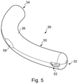
- the needle covering and carrying device is shown in the perspective view of FIGS. 4, 5 and 6 , which are taken from different angles, and is indicated generally by reference numeral 26 .
- the device 26 serves for covering a curved needle 28 , which is shown in FIG. 3 , as well as for carrying the needle within a lumen of a tendon sheath, in this case the sheath 20 shown in FIGS. 2 and 3 .
- the device 26 in the illustrated embodiment comprises an elongate element 30 having a first end 32 (which is suitably rounded or tapered), a second end 34 opposite the first end, and a body 36 extending between the first and second ends.
- the body 36 has a generally cylindrical tubular shape, and is generally circular in cross-section.
- the body 36 can, however, have other shapes, including a rectangular cross section (not shown in the drawing).
- the body 36 defines an internal cavity 38 for at least partially or entirely accommodating the curved needle 28 so that at least a penetrating tip 40 of the needle is disposed within the body 36 , the cavity shown in FIG. 7 , which is a perspective view of the body in an open position (which will be discussed in more detail below). This serves to protect the tendon sheath 20 from damage through contact with the needle 28 (particularly the tip 40 ) during passage of the needle 28 within the sheath.
- the body is substantially rigid, and has a curved shape suited to accommodate the curved needle 28 .
- the cavity 38 is shaped to receive the entire needle 28 , so that the needle is shrouded or enveloped by the body.
- the cavity 38 desirably extends from the first end 32 of the device 26 to the second end 34 , the first end forming a leading end and the second end a trailing end of the device.
- the first end 32 is closed, and the second end 34 is open and communicates with the cavity 38 .
- the open second end 34 may additionally or alternatively facilitate insertion of the needle 28 into the cavity 38 , through the open end.
- the body 36 serves for transporting the needle 28 within the tendon sheath 20 , which is achieved by inserting the first end 32 of the body into the sheath 20 and directing it along the sheath.
- Transportation of the body 36 along the sheath 20 is achieved using a transportation assembly, as shown in FIG. 8 , which is a view similar to FIG. 3 , showing a further step in the method employing the device 26 .
- the transportation assembly is indicated generally by reference numeral 42 , and comprises an elongate threading element (or threader) 44 and a flexible connecting component 46 connected to the threader.
- the threader 44 suitably takes the form of a rod or wire having a blunt (rounded) end 48 (which facilitates passage along the sheath 20 whilst reducing the risk of damage to the sheath) and an eye or ring 50 (or similar coupling element) for coupling to the connecting component 46 .
- the connecting component 46 in certain embodiments is flexible, and suitably takes the form of a cord, wire, filament or the like, particularly a medical suture. One end of the connecting component 46 can be secured to the eye or ring 50 , such as by tying off the end of the connecting component to the eye or ring 50 .
- the body 36 includes a coupling 52 ( FIG.
- the eye 52 serves for connecting the device 26 to the transportation assembly 42 , specifically to the connecting component 46 (e.g., a suture), such as by threading the adjacent end of the connecting component 46 through the eye 52 and tying off that end of the connecting component.
- the connecting component 46 e.g., a suture
- the device 26 can be drawn through the tendon sheath 20 using the transportation device 42 , by passing the threader 44 through the sheath trailing the device 26 behind it, which is connected to the threader by the connecting component 46 .
- the cavity 38 is curved, and has a curved shape which substantially matches that of the needle 28 .
- the needle 28 has a radius of curvature R 1 ( FIG. 3 )
- the cavity 38 has a radius of curvature R 2 ( FIG. 7 ), which may be taken to a centreline 54 of the cavity.
- the radius of curvature R 2 of the cavity 38 substantially matches the radius of curvature R 1 of the needle 28 , so that the cavity can comfortably accommodate the needle. However, it will be understood that small differences in these radii will not prevent the needle 28 from being accommodated within the cavity 38 .
- the body 36 in the illustrated embodiment comprises a first body part 56 and a second body part 58 , which is pivotably coupled to the first body part.
- the first and second body parts 56 and 58 when coupled, together form the body 36 .
- the first and second body parts 56 and 58 are pivotable relative to one another between an open position ( FIG. 7 ) in which the needle 28 can be inserted into the cavity 38 , and a closed position ( FIG. 4 ) in which the cavity is closed so as to securely contain the needle within the cavity during passage within the lumen of the tendon sheath 20 . Pivoting movement of the first and second body parts 56 and 58 relative to the other is facilitated by a hinge 59 , which may suitably take the form of a living hinge, coupling the first and second body parts to each other.
- the body 36 can be locked in its closed position, by means of a lock comprising a tab 60 on the second body part 58 , which engages in a recess 62 in the first body part 56 .
- the tab 60 and recess 62 may lock the body 36 in its closed position by appropriate dimensioning of the tab and recess (e.g. by providing the tab 60 of a length which resists pivoting movement of the parts 54 and 56 relative to one another when the tab is disposed in the recess), and/or by making the tab 60 resilient so that it imparts a restraining force on the part 56 when it is located in the recess 62 .
- the tab 60 can be manually depressed or moved out of engagement with the recess 62 to unlock the lock and permit pivoting of the first and second body parts to the open position.
- Suitable materials for the body include plastics, particularly polymeric materials, metals and metal alloys.
- a first step the proximal portion of the tendon 14 is retracted via opening 15 to expose the first stump 16 outside the skin, as shown in FIG. 1 .
- the finger 18 is then laid open by making one or more incisions and peeling back the skin, as show in FIG. 2 , and the second tendon stump 22 located.
- the curved needle 28 is typically supplied with a suture 64 secured to the needle at a first end 66 (such as by crimping the needle around an end portion of the suture), and has a second, free end 68 , which is shown in the enlarged detail view in FIG. 3 .
- the needle 28 , trailing the suture 64 is then passed through the first tendon stump, as also shown in the enlarged detail view in FIG. 3 . In this way, the suture 64 is connected to the first tendon stump 16 .
- the body 36 of the needle carrying device 26 is then moved to its open position, by pivoting the body parts 54 and 56 relative to one another, towards the open position shown in FIG. 7 .
- the needle 28 is then positioned in a part of the cavity 38 defined by one of the body parts, with the suture 64 trailing from the needle passing out of the body through the open second end 34 .
- the free end 68 of the suture 64 is then also placed within the cavity 38 , trailing out of the open second end 34 .
- the suture 64 is thus formed into a loop trailing from the needle 28 and out of the body 36 , through the first tendon stump 16 and then back into the body 36 .
- the body 36 can then be closed, retaining the curved needle 28 , and the second end 68 of the suture 64 , within the cavity 38 defined by the body. In this way, the sharp penetrating tip 40 of the needle 28 in particular is covered by the device 26 .
- the body 36 can include multiple cavities 38 , such as one cavity sized to receive the needle 28 and another cavity sized to receive the free end 68 of the suture 64 .
- the free end 68 of the suture 64 need not be placed inside of the device 26 and instead can be otherwise secure to a location on the outside of the device such that the suture 64 still forms a loop extending from the needle 28 .
- the blunt end 48 of the threader 44 is then inserted through the opening 15 in the palm 12 , and directed into the tendon sheath 20 . It will be understood that, in order to withdraw and expose the first tendon stump 14 , an aperture (not shown) may need to be formed in the tendon sheath. Typically, the threader 44 will be directed into the tendon sheath 20 through that aperture.
- the first end 32 of the device 26 which is connected to the threader 44 by the suture 46 , is then fed into tendon sheath 20 through the aperture in the portion of the sheath contained in the palm 18 .
- the threader 44 is then passed through the tendon sheath 20 to the vicinity of the second tendon stump 22 , and is directed out of the sheath through another surgically formed aperture 70 ( FIG. 8 ).
- the threader 44 carries the device 26 through the sheath 20 , via the connecting component 46 .
- the threader 44 is then pulled away from the tendon sheath, drawing the device 26 containing the curved needle 28 and the second end 68 of the suture 64 out of the sheath, as shown in FIG. 8 .
- the second tendon stump 22 is exposed from the finger 18 , ready for connection to the first tendon stump 16 .
- the needle 28 and the second end 68 of the suture 64 can then be removed from the cavity 38 in the body 36 .
- the suture 64 is then used to draw the first tendon stump 16 through the tendon sheath 20 , which will require suitable manipulation of the stump into the aperture in the portion of the sheath contained in the palm 12 .
- the first tendon stump 16 is drawn along the sheath 20 and out of the aperture 70 , so that it is exposed from finger 18 proximate the second tendon stump 22 (which is also exposed ready for connection to the first stump).
- the curved needle 28 trailing the suture 64 , is then passed through the second tendon stump 22 using a suitable stitching pattern (such as a modified Kessler stitch), to connect the suture to the second tendon stump.
- the suture 64 and needle 28 are then manipulated to tighten the stitch and securely connect the first tendon stump 16 to the second tendon stump 22 , thereby repairing the severed tendon 14 , which can be manipulated back into the position within the tendon sheath 20 .
- the operation can then be completed by carrying out any required remediation to the tissue (such as repositioning portions of the tendon sheath, pulleys and the like), and the openings (or incisions) in the palm 12 and finger 18 can then be closed.
- FIG. 9 there is shown a side view of a needle covering and carrying device in accordance with another embodiment of the present invention, the device indicated generally by reference numeral 26 a .
- the device 26 a shown in FIG. 9 with the device 26 shown in FIGS. 4 to 8 share the same reference numerals with the addition of the suffix ‘a’. Only the substantive differences between the device 26 a and the device 26 will be described in detail herein.
- the device 26 a comprises a first end 32 a , a second end 34 a opposite the first end, and a body 36 a extending between the first and second ends.
- the first end 32 a is suitably tapered or rounded, in order to facilitate entry into and passage along the tendon sheath 20 .
- the body 36 a defines a cavity or lumen 38 a for receiving the curved needle 28 and the trailing end 68 of the suture 64 , in the fashion described above in relation to the device 26 .
- the body 36 a can have separate cavities or lumens for receiving the needle 28 and the trailing end 68 of the suture, respectively.
- a part 72 of the body 36 a defines the cavity 38 a , and is plastically deformable.
- the entire body 36 a can be plastically deformable.
- the device 26 a is therefore capable of being bent into a required shape, to accommodate the curved needle 28 , either manually and/or using one or more tools. This may occur either on insertion of the needle 28 into the cavity 38 a , or in advance such as by appropriate manipulation of the body to have a shape which suits a particular needle.
- Suitable plastically deformable materials for forming the portion 72 , and optionally the entire body 36 a particularly include metals and metal alloys.
- At least the portion 72 of the body 36 a is tubular and may be a generally cylindrical tubular.
- the needle 28 and trailing end 68 of the suture 64 are both inserted into the cavity 38 a through the second end 34 a , which is open as shown in FIG. 9 . Insertion of the needle 28 and trailing end 68 is illustrated in the enlarged perspective views of FIGS. 10 and 11 , which show progressive insertion of these parts in the cavity 38 a .
- the device 26 a can include a coupling, such as the coupling eye 52 of the device 26 .
- the device 26 a may be capable of being used without a transportation assembly 42 .
- the body 36 a may form a threading element (threader) which is adapted to transit along the tendon sheath 20 .
- the body 36 a in the illustrated embodiment therefore comprises a threading portion 74 and the portion 72 , which forms a cover for the needle 28 .
- the threading portion 74 desirably is substantially straight, which may facilitate transit along the tendon sheath 20 .
- the cover portion 72 is capable of being deformed into the required curved shape to accommodate the curved needle 28 , although it is envisaged that the entire body 36 a can be plastically deformable to ease manufacture.
- FIG. 12 there is shown a side view of a needle covering and carrying device in accordance with another embodiment of the present invention, the device indicated generally by reference numeral 26 b .
- the device 26 b shown in FIG. 12 with the device 26 shown in FIGS. 4 to 8 , or the device 26 a shown in FIGS. 9 to 11 share the same reference numerals with the addition of the suffix ‘b’, or the suffix ‘a’ replaced with suffix ‘b’, as appropriate. Only the substantive differences between the device 26 b and the devices 26 and 26 a will be described in detail herein.
- the device 26 b comprises a first end 32 b , a second end 34 b opposite the first end, and a body 36 b extending between the first and second ends.
- the first end 32 b is again tapered or rounded, to facilitate entry into and passage along the tendon sheath 20 .
- the body 36 b defines a cavity 38 b (or multiple cavities) for receiving the curved needle 28 and the trailing end 68 of the suture 64 , in the fashion described above in relation to the device 26 .
- a part 72 b of the body 36 b defines the cavity 38 b , and is elastically deformable.
- the entire body 36 b can be elastically deformable.
- the device 26 b is therefore capable of adopting a curved shape when the needle 28 is inserted into the cavity 38 b.
- the portion 72 b (and optionally the entire body 36 b ) is elastically deformable from an undeformed or starting configuration, which may be a substantially straight and/or unstressed configuration, to a deformed or deployed configuration shown in FIG. 12 , which is a curved configuration.
- the portion 72 b will return to the undeformed configuration when the needle 28 is removed from the cavity 38 b .
- Suitable materials for forming the portion 72 b , and suitably the entire body 36 b include metals and metal alloys.
- the portion 72 b takes the form of a spring, in particular a helically wound tension spring, comprising a plurality of turns or coils 76 .
- the coils 76 are typically arranged so they are in close abutment, at least in a rest state, which may resist entry of tissue in between the coils.
- the body 36 b or just the portion 72 b , can comprise an elastically deformable polymeric tube (e.g., medical grade silicone tubing) or a tube formed from a shape memory metal (e.g., Nitinol), which can be formed with axial and/or circumferential slots to facilitate bending of the tube.
- a shape memory metal e.g., Nitinol
- the device 26 b also comprises an outer sheath, sleeve or covering 78 , which eases passage of the device within the tendon sheath 20 .
- the outer sheath 78 may be of a plastics (suitably polymeric; e.g., a layer of a heat shrink polymer) or elastomeric material, which materials may have a low coefficient of friction, to facilitate passage of the device along the tendon sheath 20 .
- the outer sheath 78 has an inner surface 80 which is disposed in contact with an outer surface 82 of the body 36 b , in particular the spring. In this way, the coils 76 of the spring are covered to resist tissue entry.
- the outer sheath 78 is tubular, and extends part way along a length of the spring 36 b .
- the outer sheath 78 extends in a direction from the first, leading end 32 b towards the second, trailing end 34 b .
- the outer sheath 78 stops short of the portion 72 b defining the cavity 38 b , so that the second end 34 b is exposed. This is desirable because it ensures that the outer sheath 78 does not restrict the elastic deformation of the portion 72 b , which is required in order to accommodate the curved needle 28 .
- the outer sheath may extend the full length of the spring 36 b , or indeed a shorter distance to that shown, so that it covers just the leading end 32 b and a small adjacent part of the spring.
- the threading element 26 b will have a length in the region of 150 mm, around 85 to 100 mm of which will be covered by the outer sheath 78 .
- the remainder (which forms the portion 72 b ), around 50 to 65 mm in length, is uncovered so as to ease deformation of the portion to accommodate the curved needle 28 .
- the device 26 b may be drawn along the tendon sheath 20 using a transportation assembly such as the assembly 42 , or can form a threader 74 b , as described in relation to the device 26 a .
- the outer sheath 78 may act to stiffen the device to resist elastic deformation during transit along the tendon sheath 20 , as well as easing passage by resisting entry of tissue into the spring coils and providing a low friction outer skin.
- FIG. 13 there is shown a view of the hand 10 of the patient as shown in FIG. 2 , illustrating steps in a method of lining a tendon sheath, employing an assembly, in accordance with an embodiment of the present disclosure.
- the method of lining the tendon sheath may also form a preparatory step to the method of repairing a severed tendon shown in FIGS. 1 to 12 and described above.
- the assembly comprises a threading element 26 b which is adapted to transit along a lumen 84 of the tendon sheath 20 .
- the threading element 26 b is provided by the needle covering and carrying device shown in FIG. 12 and described above, and so is indicated by the same reference numeral. It will be understood that further features of the threading element 26 b are outlined above. Other threading elements, including the threading element 26 a shown in FIG. 9 , may be employed. Equally, the method may make use of the assembly shown and described in FIGS. 1 to 8 .
- the assembly also comprises a liner 86 for lining an internal surface 88 of the tendon sheath 20 , the liner defining an internal passage 90 along which a tendon stump can pass during transit along the lumen 84 .
- the liner 86 acts to prevent contact between the tendon stump and the internal surface 88 of the tendon sheath 20 .
- the liner 86 is shown separately in FIG. 14 , whilst FIG. 15 shows an alternative embodiment of liner indicated generally by reference numeral 86 c .
- the liners 86 and 86 c will be discussed in more detail below.
- the liner 86 is adapted to be releasably coupled to the threading element 26 b so that it can be drawn into the tendon sheath 20 by the threading element and located within the lumen 84 , and then released from the threading element so as to reside within the lumen.
- FIG. 16 shows the liner 86 following location within the lumen 84 of the tendon sheath 20 , the liner 86 protruding at one end from the opening 15 in the palm 12 , and at the other end from the aperture 70 in the finger 18 .
- the liner 86 is therefore of a length which is selected so that the liner can pass along the entire length of tendon sheath extending between the opening 15 and the aperture 70 , with first and second open ends 92 and 94 of the liner 86 exposed respectively from the palm 12 and the finger 18 .
- the liner 86 restricts contact between other objects and the internal surface 88 of the tendon sheath 20 , including but not restricted to the threader 26 b itself, when the threader is passed back along the lumen 84 of the tendon sheath 20 in the repair procedure, as will now be described with reference also to FIG. 17 , which shows a further step in the repair method.
- the assembly further comprises a flexible connecting component for releasably connecting the threading element 26 b to the liner 86 , the connecting component shown in FIG. 13 and given the reference numeral 96 .
- the connecting component 96 typically takes the form of a medical suture, but may comprise any suitable cord, wire, filament or the like.
- the suture 96 can be secured to the threading element 26 b , such as by whipping the suture around the threading element, as shown in the enlarged view of FIG. 18 , the whipping indicated at 98 in the drawing. This secures the suture 96 against movement along a length of the threading element 26 b when it is drawn along the lumen 84 of the tendon sheath 20 , trailing the liner 86 .
- the suture 96 can be formed into a loop and can also be connected to the liner 86 , such as by whipping, as shown in the detail view of FIG. 19 , the whipping illustrated by numeral 100 .
- the whipping 100 desirably is secured around the liner 86 at a location which is spaced from the first open end 92 .
- the part of the liner 86 extending between the open end 92 and the whipping 100 can then be folded back on itself to the position shown in FIG. 13 . This provides the advantage that the open end 92 is folded back on itself, smoothing passage of the liner 86 along the lumen 84 and restricting contact between edge surfaces of the liner 86 at the open end 92 , by facing the edge surfaces away from the direction of transit.
- the liner 86 in the illustrated embodiment is elongate and generally tubular, taking the form of a sheath, as shown in FIG. 14 . Whilst the liner 86 is shown as being tubular and generally circular in cross-section, it will be understood that it may have any suitable cross-sectional shape.
- the liner 86 desirably is formed so as to be collapsible, or adapted to be flattened, for easy insertion into and transit along the lumen 84 . This is achieved by selection of suitable flexible materials for the liner, which include polymeric and elastomeric materials, and/or by providing the liner with a wall thickness which is suitable for promoting collapsing/flattening. Suitable wall thicknesses may be of the order of fractions of a millimetre.
- the leading end 32 b of the threading element 26 b can be inserted into the lumen 84 at the aperture 70 in the finger 18 .
- the threading element 26 b can then be pushed along the lumen 84 until the leading end 32 b protrudes from the opening 15 in the palm 12 .
- the threading element 26 b can suitably be of a length which is such that the threading element spans the entire length of the tendon sheath 20 extending between the opening 15 and the aperture 70 .
- the trailing end 34 b of the threading element 26 b will protrude from the opening 70 in the finger 18 after the leading end 32 b has exited the lumen 84 through the opening 15 in the palm 12 .
- This enables the threading element 26 b to be drawn out of the tendon sheath 20 by grasping the leading end 32 b and pulling the threading element.
- Transit of the threading element 26 b along the lumen 84 of the tendon sheath 20 acts to move the liner 86 towards the opening 70 in the finger 18 , due to its connection to the threading element via the suture 96 .
- the surgeon can grasp the portion of the suture 96 which has been exposed at the palm 12 and pull on the suture in order to draw the liner 86 into the opening 70 , suitably using medical pliers or forceps to hold the folded portion of the liner down, and to manipulate the folded portion into the lumen 84 at the opening 70 .
- the surgeon can then pull on the suture 96 to advance the liner 86 into the position shown in FIG. 16 , where it spans the opening 15 and aperture 70 as described above.
- the threading element 26 b can then be released from the liner 86 , suitably by cutting the suture 96 and removing any portions of the suture coupled to the threading element 26 b . Additionally, the surgeon can cut the liner 86 at a position which is spaced further away from the open first end 92 then the whipping 100 , so as to remove the folded and whipped portion, thereby reopening the liner 86 . However, alternatively, the whipping 100 can be removed so as to reopen the liner 86 .
- the surgeon can then secure the suture 64 to the tendon stump 16 using the curved needle 28 (not shown in FIG. 16 ), and position the curved needle and the second free end 68 of the suture 64 within the deformable part 72 b of the threading element 26 b .
- Positioning the curved needle 28 within the deformable part 72 b causes the deformable part to adopt the deformed position shown in FIG. 16 .
- the threading element 26 b can then be inserted back into the lumen 84 , by passing the leading end 32 b into the open end 92 of the liner 86 , and the threading element can be passed along the internal passage 90 defined by the liner.
- the threading element 26 b transits along the tendon sheath 20 pulling the suture 64 , exiting the sheath at the aperture 70 in the finger 18 .
- the liner 86 lines the internal surface 88 of the tendon sheath 20 , to prevent contact between the threading element 26 b and the sheath surface.
- the curved needle 28 and the free end 68 of the suture 64 can then be removed from the deformable part 72 b of the threading element 26 b , as shown in FIG. 17 .
- the suture 64 can then be used to draw the first tendon stump 16 into the internal passage 90 defined by the liner 82 , by manipulating the tendon stump into the liner opening 92 , as shown in the drawing.
- the first tendon stump 16 is then drawn along the tendon sheath 20 , the liner 86 similarly serving to restrict contact between the tendon stump 16 and the sheath surface 88 . This continues until the first tendon stump 16 emerges from the opening 70 in the finger 18 .
- the liner 86 can then be withdrawn from the lumen 84 of the tendon sheath 20 , by sliding the liner over the outer surface of the portion of the tendon located in the lumen, and over the suture 64 and needle 28 .
- the tendon stumps 16 and 22 can then be sutured together to restore function to the tendon 14 , following the procedure discussed in detail above.
- the liner 86 may remain in the lumen 84 until after the stumps 16 and 22 have been sutured, and is then removed by pulling on the liner and cutting it as it is exposed from the aperture 70 .
- the liner 86 c includes a slit 102 which extends along an entire length of the liner from its first end 92 c to its second end 94 c .
- the liner 86 c can be rolled or coiled about its longitudinal axis into the shape of a tube, so as to define an internal passage 90 c .
- the liner 86 c can be rolled into the tube shape by arranging a first longitudinal edge 104 so that it overlaps a second longitudinal edge 106 .
- the provision of a liner 86 c having such a slit 102 facilitates removal of the liner from the lumen 84 after completion of the tendon repair procedure, in which tendon stumps 16 and 20 are connected, because the slit 102 enables the liner 86 c to be drawn over the repaired tendon leaving the tendon in place within the lumen 84 .
- the liner 86 c need not be rolled or coiled, and instead the first longitudinal edge 104 can abut or be in close proximity to the second longitudinal edge 106 .
- FIGS. 18, 20 and 21 Variations on the method of coupling the suture 96 to the threading element 26 b are shown in FIGS. 18, 20 and 21 .
- the suture is whipped and securely knotted on the external surface of the sheath covering the threading element.
- the suture 96 is whipped directly to the outer surface 82 of the spring 36 b , and the sheath 78 located over the whipping 98 to trap the suture between the outer surface 82 and the inner surface 80 of the sheath 78 .
- at least a portion of the suture 96 extending along or around the spring 36 b can be captured between the spring and the sheath 78 when the sheath is formed from a layer of a heat shrink polymer around the spring.
- the suture 96 ends 108 and 110 are inserted through an internal passage 112 defined by the spring 36 b and through an open end 114 of the spring, and then passed away from the open end along the outer surface 82 of the spring.
- the sheath 78 is then located over the suture ends 108 and 110 , trapping them between the outer surface 82 of the spring 36 b and the inner surface 80 of the sheath 78 .
- ends of the suture 96 can be positioned along the outer surface 82 of the spring 36 b (without being whipped to the spring) and are trapped by the sheath 78 .
- the suture ends 108 and 110 may also be whipped to the spring 36 b , after exiting the open end 114 . Further variations can be envisaged based on combinations of the options discussed above.
- the same threading element 26 b is used to position the liner 86 within the tendon sheath and to thread the needle and the suture 64 through the liner 86 .
- two threading elements 26 b can be used to perform these two steps.
- a different type of threading element can be used to position the liner 86 within the tendon sheath than is used to thread the needle and the suture through the liner.
- the threading element used to position the liner 86 within the tendon sheath need not have a curved portion or a portion that is deformable to form a curved shape when a needle is inserted into the threaded element.
- the threading element used to position the liner 86 within the tendon sheath can comprise an elongated body (e.g., a tubular body) and a connecting component (e.g., a suture or wire, such as in the form of a loop) connected to the elongated body, wherein the connecting component is configured to be releasably coupled to a liner as described herein.
- a connecting component e.g., a suture or wire, such as in the form of a loop
- FIG. 22 , and FIGS. 23A /B and 24 show alternative liners 86 d and 86 e .
- Like components of the liners 86 d and 86 e with the liner 86 shown in FIGS. 13 to 17 and described above share the same reference numerals, with the addition of the suffixes ‘d’ and ‘e’, respectively.
- the liner 86 d comprises a sheath lining portion 116 adapted to be located within the lumen 84 for lining the tendon sheath 20 , and a pulling portion 118 extending from the lumen lining portion.
- the pulling portion 118 can be used to pull the sheath lining portion 116 into and along the lumen 84 before being severed, leaving the lining portion within the lumen.
- the pulling portion 118 can have a length which is greater than, or substantially equal to, a length of the sheath lining portion 116 .
- the threading element 26 b can be coupled to the pulling portion 118 , such as using the connecting component 96 as described above, and used to draw the pulling portion into the lumen 84 in the fashion described above.
- the pulling portion 118 is then used to draw the sheath lining portion 116 into the lumen 84 , by pulling an end 120 of the pulling portion 118 out of the lumen 84 .
- the pulling portion 118 can be gripped by a surgeon and used to pull the sheath lining portion 116 into the lumen 84 .
- the sheath lining portion 116 can be substantially tubular, and the pulling portion 118 can comprise one or more elongate strips, legs or the like, which extend from the tubular lumen lining portion, and which can be provided integrally with the lining portion.
- the liner 86 d can be coupled to the threading element 26 b by inserting the liner 86 d partially into the loop formed by the connecting component 96 and folding the portion 118 over the loop against the portion 116 , such as at a location on or adjacent a tapered transition section 122 between portions 116 , 118 .
- the pulling portion 118 can be of reduced width W P in comparison to a width W L of the lining portion 116 e , which may facilitate insertion of the liner 86 d into the lumen 84 of the tendon sheath 20 , and transit of the liner along the lumen. This is typically achieved by cutting away sections 119 and 121 of the tubular structure of the liner 86 d .
- edges of the legs forming the pulling portion 118 can be sealed together, for example by preforming the cutting procedure using a hot knife. Sealing the edges may further facilitate insertion of the liner 86 d into the lumen 84 , and transit along the tendon sheath.
- FIG. 23A shows the liner 86 e , which is a variation on the liner 86 d in which a length of a pulling portion 118 e is less than a length of a sheath lining portion 116 e .
- FIG. 23B shows the suture 96 coupled to the liner 86 e , optionally by folding over a part of the liner including an open end 92 e , and securing the folded part using whipping 124 and 126 which passes around the folded portion.
- the liner 86 e is folded in the region of the pulling portion 118 e , which maintains the reduced width (W P in FIG.
- FIGS. 24A and 24B show an alternative liner, which may have a use in the repair of two severed tendons.
- the liner is indicated by reference numeral 86 f .
- Like components of the liner 86 f with the liner 86 shown in FIGS. 13 to 17 and described above share the same reference numerals, with the addition of the suffix ‘f’.
- the liner 86 f can be coupled to a connecting component 96 of a threading element (e.g., the threading element 26 b ) so as to define two tendon sheath lining portions 138 and 140 .
- the liner 86 f has a first end 142 and a second end 144 , and coupling is achieved by connecting the liner to the connecting component 96 at a point 146 along a length of the liner between the first and second ends, suitably at or proximate a midpoint of the liner.
- each tendon sheath lining portion 138 and 140 is substantially the same, although the lengths could be different, provided that they are sufficiently long to line the tendon sheath 20 (or at least the part of the tendon sheath extending between the surgical openings 15 and 70 ).
- the tendon sheath lining portions 138 and 140 serve for receiving the tendon stumps of respective tendons, which are normally located in the tendon sheath 20 . It is well known that the tendon sheath 20 in the finger 18 accommodate more than one tendon.
- the assembly comprising the liner 86 f can therefore enable the two tendon sheath lining portions 138 and 140 to be located in the tendon sheath 20 , for use where both of the finger tendons are to be repaired.
- the liner 86 f also comprises a body 148 extending between the first and second ends 142 and 144 .
- the first tendon sheath lining portion 138 extends from the first end 142 towards a part 118 f of the liner disposed between the first and second ends, and which will form a pulling portion.
- the second tendon sheath lining portion 140 extends from the second end 144 towards the part 118 f .
- the first and second tendon sheath lining portions 138 and 140 each have a width W L2
- the part 118 f has a width W P2 which is less than the width of the first and second tendon sheath lining portions.
- the width of the first tendon sheath lining portion 138 is suitably the same as (or substantially the same as) the width of the second tendon sheath lining portion 140 .
- the liner 86 f can have constant width of a substantially constant width from the first end 142 to the second end 144 .
- the part 118 f comprises a main section 150 of substantially constant width, a first transition section 152 extending between the main section 150 and the first tendon sheath lining portion 138 , and a second transition section 154 extending between the main section 150 and the second tendon sheath lining portion 140 .
- the transition sections 152 and 154 have a width which progressively increases from the width W P2 of the main section 150 to the width W L2 of the respective tendon sheath lining portion 138 , 140 . Typically, this will be achieved by cutting away sections of the tubular structure of the liner 86 f , as described above.
- the liner 86 f is adapted to be releasably coupled to the threading element 26 b , in particular the flexible connecting component 96 , in the part 118 f .
- the liner 86 f is releasably coupled to the threading element by folding it over the loop at the part 118 f .
- the liner 86 f is then drawn into the tendon sheath 20 as described above.
- the first and second tendon sheath lining portions 138 and 140 can then be separated from one another, suitably by severing the liner 86 f . This may be achieved by removing the portion 118 f , for example by cutting the liner at the location 158 , to the left of the transition portions 152 and 154 in FIG. 24B .
- the portion 118 f comprises the first transition section 152 extending from the first tendon sheath lining portion 138 , and the second transition section 154 extending from the second tendon sheath lining portion 140 , the second transition section being coupled to the first transition section.
- the transition sections 152 and 154 have a width which progressively increases from a width W I defined at an intersection 156 between the transition sections, to the width W L2 of the respective tendon sheath lining portions 138 and 140 .
- the liner embodiment 86 f shown in FIGS. 24A to C effectively comprises two tubular liners unitarily and symmetrically connected by two transition sections 152 and 154 , reducing in width to form a section of uniform width 118 f , similar to that of the pulling portion shown as 118 in FIG. 22 and FIGS. 23A and B.
- FIG. 24B shows how the liner 86 f is coupled to the loop 96 connected to the threading element 26 b .
- the liner 86 f may be formed by removing material from the middle portion of a long tubular liner. Also, it is acceptable not to have the narrowed section of 118 f shown in FIGS. 24A and B, but to include only the transition sections 152 and 154 as in FIG. 24C .
- This embodiment has two advantages: (i) simpler coupling and decoupling of the liner to the loop extending from the threading needle; and (ii) as two full length liners would be placed in the lumen of the tendon sheath, it would be possible to repair two ruptured tendons in the same finger (this occurs with some frequency), and in this case each liner would facilitate the delivery of one tendon stump at a time from the palm to the finger tip, again following the procedure that has been described elsewhere.
- FIGS. 25 and 26 there are shown side views of an assembly in accordance with another embodiment of the present disclosure.
- the assembly may be employed in a method of retrieving a tendon stump of a severed tendon, which involves lining the tendon sheath as a preparatory step to repairing the severed tendon.
- the assembly and method will be described with reference to the repair of a severed tendon in the hand, as described above.
- the assembly comprises a threading element 26 b which is adapted to transit along a lumen 84 of the tendon sheath 20 .
- the threading element 26 b is provided by the needle covering and carrying device shown in FIG. 12 and described above, and so is indicated by the same reference numeral. It will be understood that further features of the threading element 26 b are outlined above. Other threading elements may, however, be employed.
- the assembly again comprises a liner for lining an internal surface 88 of the tendon sheath 20 , the liner indicated generally by reference numeral 86 f .
- the liner 86 f Like components of the liner 86 f with the liners 86 to 86 e share the same reference numerals, with the suffix ‘f’.
- the liner 86 f defines an internal passage 90 f along which a tendon stump can pass during transit along the lumen 84 , and again acts to prevent contact between the tendon stump and the internal surface 88 of the tendon sheath 20 .
- the liner 86 f is similar to the liners 86 to 86 e shown in FIGS. 13 to 24 and described above, but is connected to the threading element 26 b in a different way.
- the liner 86 f comprises a sheath lining portion 116 f adapted to be located within the lumen 84 (for lining the tendon sheath 20 ), and a pulling portion 118 f extending from the lumen lining portion.
- the pulling portion 118 f is folded over the loop formed by the suture 96 , but is secured by fixing a folded part 128 of the pulling portion 118 f to a main part 130 of the liner 86 f , suitably by welding (e.g. application of heat) or using an adhesive, as shown at 132 in FIG. 25 .
- the liner 86 f has a collapsed, rest configuration in which it is adapted to be inserted into the lumen of the tendon sheath, and an expanded, operating configuration.
- the liner 86 f is shown in the collapsed, rest configuration in the perspective view of FIG. 25A , and in the expanded, operating configuration in FIG. 25B .
- the liner 86 f is movable to the radially expanded configuration by contact with a tendon stump, in this case the first tendon stump 16 in the palm, as it moves along the lumen 84 of the tendon sheath 20 .
- the liner 86 f is substantially flat (optionally taking the form of a lay-flat tube), having a width W and a height H, the width being greater than the height.
- the internal passage 90 f defined by the liner 86 f becomes enlarged or opens up, so that the liner becomes more rounded (circular or elliptical) in shape. This causes the width W to decrease and the height H to increase. This may be achieved by flattening the liner 86 f , for example by winding it on to a reel prior to connecting it to the threading element 26 b .
- the liner may have longitudinally extending seams or fold lines 134 and 136 , spaced apart around a perimeter of the liner (although the seams may be deliberately formed, e.g. prior to winding on to a reel, if used), so that the liner looks like a flat tape when unreeled.
- the ‘lay-flat’ structure of the liner 86 f offers significant advantages over the dilation catheter disclosed in US-2013/0144310A1, in that avoids the over-dilation of tendon pulleys which can occur when using the rigid dilation catheter disclosed in the document, thereby reducing a risk of damage/rupture of the pulleys.
- the liner 68 f can have a wall thickness in the range of around 0.05 to around 0.2 mm, and so the height H in its collapsed (flat), rest configuration may be relatively small, for example, in the range of around 0.1 to around 0.4 mm (potentially up to around, for example, 0.5 mm depending upon how much the passage 90 f is closed in the collapsed configuration). This ensures that the liner 86 f occupies only a small portion of the lumen 84 , and so does not interfere with or constrain transport of the tendon stump 16 along the lumen.
- the width W in comparison can be in the range of from about 5 to about 10 mm.
- Suitable materials for the liner 86 f include polymeric materials, particularly low density polyethylene, which may be suitable for heat welding to connect it to the threading element 26 b , and may facilitate flattening of the tube.
- a ratio of the height H to the width W can be in the range of from about 1:100 to about 1:10 (where W is from 5 to 10 mm and H is from 0.1 mm to 0.5 mm).
- Forming the liner 86 f so that it has a collapsed configuration can facilitate insertion of the liner into the lumen 84 of the tendon sheath 20 , in that the height H is relatively small, and significantly smaller than the width W, when in this configuration. Subsequent movement of the liner 86 f to the expanded configuration (as the tendon stump 16 passes along the internal passage 90 f ) enables passage of the stump 16 along the liner whilst ensuring that the liner does not come into contact with the pulleys or internal surface 88 of the tendon sheath 20 , the liner therefore acting to line the internal surface.
- FIG. 26 shows the assembly following disconnection of the liner 86 f (which resides in the lumen 84 of the tendon sheath 20 ), and following location of the curved needle 28 within the portion 72 b of the spring that forms the body 36 b , trailing the suture 64 .
- the first end 32 b of the body 36 b defined by the spring is rounded, to assist navigation along the lumen 84 . This may be achieved by suitable treatment of the outer sleeve 78 , for example the application of heat.
- FIGS. 27 to 30 illustrate steps in a method of retrieving the tendon stump 16 from the palm 12 to a location proximate the second tendon stump 18 (not shown in these drawings) in the finger 18 , employing the assembly of FIGS. 25 and 26 .
- the method is similar to the relevant steps of the method shown in FIGS. 13 to 21 and described above.
- FIG. 27 shows the assembly with the liner 86 f connected to the threading element 26 b via the suture 96 , the threading element being used to draw the liner into the lumen 84 of the tendon sheath 20 .
- FIG. 28 shows the liner 86 f located in the lumen following disconnection of the liner from the threading element 26 b (for example by cutting away the pulling portion 118 f at a position spaced further along the liner from the welded/glued point 132 and then removing the suture 96 from the threading element), subsequent to connection of the suture 64 to the tendon stump using the curved needle 28 , and subsequent to location of the needle 28 and the trailing end of the suture 64 within the internal cavity 38 (the tendon stump 16 is located behind the liner 86 f in FIG.
- FIG. 29 shows the threading element 26 b inserted into and directed along the internal passage 90 f defined by the liner 86 (located in the lumen 84 of the tendon sheath 20 ) trailing the tendon stump 16 .
- FIG. 30 shows the tendon stump 16 being drawn along the internal passage 90 f of the liner 86 f , the threading element 26 b having exited the aperture 70 in the finger 18 .
- the tendon stump 16 can then be sutured to the tendon stump 22 (not shown in these drawings) in the finger 18 to complete a repair procedure.
- the body may comprise a sidewall.
- An opening may be formed in the sidewall which communicates with the cavity.
- the needle may be insertable into the cavity through the opening.
- the cavity may extend part way along a length of the body.
- the cavity may extend from one of the first and second ends in a direction towards the other one of the first and second ends. Where the second end is a trailing end, the cavity may extend from the second end towards the first end.
- the device of the present invention has been shown during use in the repair of a damaged tendon in the hand (particularly, but not limited to, a severed tendon). It will be understood, however, that the device and method disclosed in this document may have a use in the repair of other tendons in the human or animal body. In general terms, the device and method may have a use in any surgical tendon repair technique which would benefit from the use of a curved needle to attach tendon stumps together and so repair the tendon, and which requires passage of the needle within a lumen of the tendon sheath.
Landscapes
- Health & Medical Sciences (AREA)
- Surgery (AREA)
- Life Sciences & Earth Sciences (AREA)
- Heart & Thoracic Surgery (AREA)
- Molecular Biology (AREA)
- Veterinary Medicine (AREA)
- Engineering & Computer Science (AREA)
- Biomedical Technology (AREA)
- Public Health (AREA)
- Medical Informatics (AREA)
- Nuclear Medicine, Radiotherapy & Molecular Imaging (AREA)
- Animal Behavior & Ethology (AREA)
- General Health & Medical Sciences (AREA)
- Orthopedic Medicine & Surgery (AREA)
- Rheumatology (AREA)
- Surgical Instruments (AREA)
- Lining Or Joining Of Plastics Or The Like (AREA)
Abstract
Description
-
- a first end;
- a second end opposite the first end; and
- a body extending between the first and second ends, the body defining an internal cavity for accommodating a curved needle so that at least a penetrating tip of the needle is disposed within the body, to protect the tendon sheath from damage through contact with the tip during passage of the needle within the sheath;
- in which the body is:
- A. substantially rigid, having a curved shape so that it can accommodate the curved needle; or
- B. deformable, and capable of being deformed into a curved shape so that it can accommodate the curved needle.
-
- a curved needle; and
- a needle covering and carrying device for covering the curved needle and carrying the needle within a lumen of a tendon sheath, the needle covering and carrying device comprising an elongate element having:
- a first end;
- a second end opposite the first end; and
- a body extending between the first and second ends, the body defining an internal cavity for accommodating a curved needle so that at least a penetrating tip of the needle is disposed within the body, to protect the tendon sheath from damage through contact with the tip during passage of the needle within the sheath;
- in which the body is:
- A. substantially rigid, having a curved shape so that it can accommodate the curved needle; or
- B. deformable, and capable of being deformed into a curved shape so that it can accommodate the curved needle.
-
- a threading element adapted to transit along a lumen of a tendon sheath; and
- a liner for lining an internal surface of the tendon sheath, the liner defining an internal passage along which a tendon stump can pass during transit along the lumen, the liner acting to restrict contact between the tendon stump and the internal surface of the tendon sheath;
- in which the liner is adapted to be releasably coupled to the threading element so that it can be drawn into the tendon sheath by the threading element and located within the lumen, and then released from the threading element so as to reside within the lumen.
-
- a first end;
- a second end opposite the first end; and
- a body extending between the first and second ends, the body defining an internal cavity for accommodating a curved needle so that at least a penetrating tip of the needle is disposed within the body, to protect the tendon sheath from damage through contact with the tip during passage of the needle within the sheath.
-
- passing a curved needle connected to a suture through a first tendon stump, to connect the suture to the first tendon stump;
- providing a needle covering and carrying device comprising an elongate element having a first end, a second end opposite the first end, and a body extending between the first and second ends, the body defining an internal cavity;
- locating at least a penetrating tip of the curved needle within the cavity defined by the body, so that the tip is covered by the device;
- inserting the first end of the elongate element into the tendon sheath;
- directing the elongate element along the tendon sheath carrying the needle and the suture, towards a second tendon stump spaced along the sheath from the first tendon stump;
- removing the needle covering and carrying device from the tendon sheath;
- removing the needle from the cavity in the body;
- drawing the first tendon stump along the tendon sheath using the suture, to a position proximate the second tendon stump, so that the tendon stumps can be connected.
-
- releasably coupling a threading element to a liner defining an internal passage;
- inserting the threading element into a lumen of a tendon sheath trailing the liner behind it;
- directing the threading element along the lumen of the tendon sheath, to draw the liner into the lumen;
- locating the liner in the tendon sheath so that it lines an internal surface of the tendon sheath;
- removing the threading element from the lumen of the tendon sheath; and
- releasing the liner from the threading element leaving the liner in place within the lumen of the tendon sheath, the liner serving to restrict contact between a tendon stump of a severed tendon and the internal surface of the tendon sheath during a subsequent tendon repair procedure.
-
- an elongate threading element adapted to transit along a lumen of a tendon sheath, for covering a curved needle and carrying the needle within the lumen of the tendon sheath, the elongate threading element having:
- a first end;
- a second end opposite the first end; and
- a body extending between the first and second ends, the body defining an internal cavity for accommodating the curved needle to protect the tendon sheath from damage through contact with the needle during passage of the needle within the tendon sheath, the body being deformable into a curved shape so that it can accommodate the curved needle, the body optionally comprising a spring having a plurality of coils;
- a liner for lining an internal surface of the tendon sheath, the liner defining an internal passage along which a tendon stump coupled to the curved needle can pass during transit along the lumen, the liner preventing contact between the tendon stump and the internal surface of the tendon sheath, the liner optionally having:
- a collapsed, rest configuration in which the liner is adapted to be inserted into the lumen of the tendon sheath; and
- an expanded, operating configuration, the liner being movable to the expanded configuration by contact with the tendon stump;
- in which the liner is adapted to be releasably coupled to the elongate threading element so that it can be drawn into the tendon sheath by the threading element and located within the lumen, and then released from the threading element so as to reside within the lumen;
- and in which the elongate threading element, once released from the liner, is adapted to receive the curved needle, for covering and carrying the curved needle through the liner and along the lumen of the tendon sheath trailing the connected tendon stump.
- an elongate threading element adapted to transit along a lumen of a tendon sheath, for covering a curved needle and carrying the needle within the lumen of the tendon sheath, the elongate threading element having:
-
- providing an elongate threading element having a first end, a second end opposite the first end, and a body extending between the first and second ends and having an internal cavity, the body being deformable into a curved shape, the body optionally comprising a spring having a plurality of coils;
- releasably coupling the elongate threading element to a liner defining an internal passage, the liner optionally having a collapsed, rest configuration and an expanded, operating configuration;
- inserting the elongate threading element into a lumen of a tendon sheath trailing the liner behind it, optionally with the liner in the collapsed configuration;
- directing the elongate threading element along the lumen of the tendon sheath to draw the liner into the lumen, and locating the liner in the tendon sheath so that it can line an internal surface of the tendon sheath;
- removing the elongate threading element from the lumen of the tendon sheath and releasing the liner from the threading element leaving the liner in place within the lumen;
- passing a curved needle trailing a suture through a first tendon stump, to connect the suture to the first tendon stump;
- locating the curved needle within the internal cavity so that the needle is covered by the body and the body deformed to the curved shape by the needle;
- inserting the first end of the elongate threading element into the internal passage of the liner, and directing the threading element along the internal passage carrying the needle and the trailing suture towards a second tendon stump spaced along the tendon sheath from the first tendon stump;
- drawing the first tendon stump along the internal passage of the liner using the suture to a position proximate the second tendon stump, so that the tendon stumps can be connected, in which the first tendon stump optionally moves the liner to the expanded configuration during movement along the internal passage.
Claims (38)
Priority Applications (7)
| Application Number | Priority Date | Filing Date | Title |
|---|---|---|---|
| CN201980047610.8A CN112533545B (en) | 2018-06-18 | 2019-06-17 | Tendon repair device, assembly and method of use |
| AU2019291279A AU2019291279A1 (en) | 2018-06-18 | 2019-06-17 | Device, assembly and method for use in tendon repair |
| JP2020570548A JP7411584B2 (en) | 2018-06-18 | 2019-06-17 | Devices, assemblies and methods for use in tendon repair |
| PCT/GB2019/051686 WO2019243793A2 (en) | 2018-06-18 | 2019-06-17 | Device, assembly and method for use in tendon repair |
| CA3104216A CA3104216A1 (en) | 2018-06-18 | 2019-06-17 | Device, assembly and method for use in tendon repair |
| KR1020217001387A KR20210022660A (en) | 2018-06-18 | 2019-06-17 | Devices, assemblies and methods for use in tendon closure |
| EP19732109.4A EP3806753A2 (en) | 2018-06-18 | 2019-06-17 | Device, assembly and method for use in tendon repair |
Applications Claiming Priority (9)
| Application Number | Priority Date | Filing Date | Title |
|---|---|---|---|
| GB1809949 | 2018-06-18 | ||
| GBGB1809949.9A GB201809949D0 (en) | 2018-06-18 | 2018-06-18 | Device, assembly and method for use in tendon repair |
| GB1809949.9 | 2018-06-18 | ||
| GB1820699 | 2018-12-19 | ||
| GBGB1820699.5A GB201820699D0 (en) | 2018-12-19 | 2018-12-19 | Device. Assembly and method for use in tendon repair |
| GB1820699.5 | 2018-12-19 | ||
| GB1901357.2 | 2019-01-31 | ||
| GB1901357 | 2019-01-31 | ||
| GBGB1901357.2A GB201901357D0 (en) | 2019-01-31 | 2019-01-31 | Device, assembly and method for use in tendon repair |
Publications (2)
| Publication Number | Publication Date |
|---|---|
| US20190380713A1 US20190380713A1 (en) | 2019-12-19 |
| US11259810B2 true US11259810B2 (en) | 2022-03-01 |
Family
ID=68838661
Family Applications (1)
| Application Number | Title | Priority Date | Filing Date |
|---|---|---|---|
| US16/401,929 Active 2039-09-16 US11259810B2 (en) | 2018-06-18 | 2019-05-02 | Device, assembly and method for use in tendon repair |
Country Status (8)
| Country | Link |
|---|---|
| US (1) | US11259810B2 (en) |
| EP (1) | EP3806753A2 (en) |
| JP (1) | JP7411584B2 (en) |
| KR (1) | KR20210022660A (en) |
| CN (1) | CN112533545B (en) |
| AU (1) | AU2019291279A1 (en) |
| CA (1) | CA3104216A1 (en) |
| WO (1) | WO2019243793A2 (en) |
Citations (22)
| Publication number | Priority date | Publication date | Assignee | Title |
|---|---|---|---|---|
| US5236443A (en) | 1992-05-21 | 1993-08-17 | Sidney Sontag | Suturing assembly and method |
| US5549629A (en) | 1994-03-10 | 1996-08-27 | Thomas; Stacy I. | Apparatus for covering a surgical needle to protect the user |
| US5741299A (en) * | 1997-03-05 | 1998-04-21 | Rudt; Louis L. | Puncture-proof suture needle assembly |
| US5897591A (en) * | 1997-01-20 | 1999-04-27 | Kobayashi; Masanori | Implant for injured tendon of digitus manus |
| WO2000033746A1 (en) | 1998-12-08 | 2000-06-15 | Orthofix Inc | Tendon passing device and method |
| US20020077631A1 (en) * | 1996-09-13 | 2002-06-20 | Lubbers Lawrence M. | Apparatus and methods for tendon or ligament repair |
| WO2003003931A1 (en) | 2001-06-29 | 2003-01-16 | Herzzentrum Dresden Gmbh | Transport device for application in endoscopic surgery |
| US20090048616A1 (en) * | 2007-08-14 | 2009-02-19 | Mgh Medesign, Llc | Device and method for assisting in flexor tendon repair and rehabilitation |
| US20090131980A1 (en) * | 2007-11-20 | 2009-05-21 | Wiesman Irvin M | Tendon Cap and method for tendon repair |
| EP2108316A1 (en) | 2008-04-11 | 2009-10-14 | Tyco Healthcare Group LP | Loop suture |
| US20110087248A1 (en) | 2009-10-14 | 2011-04-14 | Steffen Dennis L | Flexor Tendon Suture Passer |
| US20110112532A1 (en) | 2009-11-10 | 2011-05-12 | Steffen Dennis L | Windowed flexor tendon sheath retractor & dilator |
| US20110172706A1 (en) * | 2010-01-13 | 2011-07-14 | Boston Scientific Scimed, Inc. | Tool delivery systems and methods of use |
| US20120071975A1 (en) * | 2010-09-10 | 2012-03-22 | Eduardo Gonzalez-Hernandez | Device and method for assisting in flexor tendon repair and rehabilitation |
| US20120226296A1 (en) * | 2010-09-01 | 2012-09-06 | Bindra Randip R | Surgical device for soft tissue repair and surgical kit including such a device |
| US20130041451A1 (en) * | 2011-08-09 | 2013-02-14 | Cook Medical Technologies Llc | Prosthesis deployment system for open surgical repair |
| US20130144310A1 (en) | 2010-02-12 | 2013-06-06 | Core Essence Orthopaedics, Inc. | Method and apparatus for repairing a tendon or ligament |
| US20140024885A1 (en) | 2012-07-20 | 2014-01-23 | Anthony E. Sudekum | Flexor tendon repair device |
| CN205569148U (en) | 2016-03-16 | 2016-09-14 | 苏州瑞华医院有限公司 | Cracked brace after prevention musculus flexor tendon repair technique |
| CN106038018A (en) | 2016-07-01 | 2016-10-26 | 南京富帆健康管理咨询服务有限公司 | Rehabilitation orthosis for rupture of finger flexor tendon |
| CN106976240A (en) | 2017-04-07 | 2017-07-25 | 新疆大学 | The design and preparation method of a kind of customization stabilizing brace after flexor tendon injury in hand reparation |
| WO2018109494A1 (en) | 2016-12-16 | 2018-06-21 | Xiros Limited | Medical probe, assembly and method |
Family Cites Families (12)
| Publication number | Priority date | Publication date | Assignee | Title |
|---|---|---|---|---|
| US6143004A (en) * | 1998-08-18 | 2000-11-07 | Atrion Medical Products, Inc. | Suturing device |
| JP4223719B2 (en) * | 1999-10-18 | 2009-02-12 | テンドン テクノロジー、リミテッド | Tendon or ligament repair device and method |
| ATE395869T1 (en) * | 2001-06-15 | 2008-06-15 | Hill Donald J | DEVICE FOR ATTACHING A SURGICAL THREAD |
| GB2385791B (en) * | 2002-02-28 | 2005-03-30 | Alexander Craig Wille Campbell | Surgical device |
| US7842046B1 (en) * | 2004-05-26 | 2010-11-30 | Granit Medical Innovations, Llc | Endoscopic sewing device and associated method |
| CN101842060B (en) * | 2007-09-21 | 2014-07-16 | Ams研究公司 | Pelvic floor treatments and related tools and implants |
| CN201189184Y (en) * | 2008-04-30 | 2009-02-04 | 刘照华 | Tendon tension suturing device |
| JP5625142B2 (en) * | 2008-06-12 | 2014-11-19 | ポンティス オーソペディクス エルエルシーPontis Orthopaedics,Llc | Repair device for repairing tendons or ligaments and apparatus comprising the repair device |
| US8936611B2 (en) * | 2010-05-27 | 2015-01-20 | Raptor Surgical, LLC | Apparatus and methods for achilles tendon repair |
| AU2012275965A1 (en) * | 2011-06-06 | 2014-05-15 | Core Essence Orthopaedics, Inc. | Method and apparatus for repairing a tendon or ligament |
| WO2016096003A1 (en) * | 2014-12-17 | 2016-06-23 | Oetiker Schweiz Ag | Tool for fastening a clamp |
| WO2017136025A1 (en) * | 2016-02-05 | 2017-08-10 | Dura Tap Llc | Devices and methods for suture placement |
-
2019
- 2019-05-02 US US16/401,929 patent/US11259810B2/en active Active
- 2019-06-17 JP JP2020570548A patent/JP7411584B2/en active Active
- 2019-06-17 CN CN201980047610.8A patent/CN112533545B/en active Active
- 2019-06-17 KR KR1020217001387A patent/KR20210022660A/en not_active Application Discontinuation
- 2019-06-17 CA CA3104216A patent/CA3104216A1/en active Pending
- 2019-06-17 WO PCT/GB2019/051686 patent/WO2019243793A2/en unknown
- 2019-06-17 EP EP19732109.4A patent/EP3806753A2/en active Pending
- 2019-06-17 AU AU2019291279A patent/AU2019291279A1/en active Pending
Patent Citations (24)
| Publication number | Priority date | Publication date | Assignee | Title |
|---|---|---|---|---|
| US5236443A (en) | 1992-05-21 | 1993-08-17 | Sidney Sontag | Suturing assembly and method |
| US5549629A (en) | 1994-03-10 | 1996-08-27 | Thomas; Stacy I. | Apparatus for covering a surgical needle to protect the user |
| US20020077631A1 (en) * | 1996-09-13 | 2002-06-20 | Lubbers Lawrence M. | Apparatus and methods for tendon or ligament repair |
| US5897591A (en) * | 1997-01-20 | 1999-04-27 | Kobayashi; Masanori | Implant for injured tendon of digitus manus |
| US5741299A (en) * | 1997-03-05 | 1998-04-21 | Rudt; Louis L. | Puncture-proof suture needle assembly |
| WO2000033746A1 (en) | 1998-12-08 | 2000-06-15 | Orthofix Inc | Tendon passing device and method |
| US6342060B1 (en) * | 1998-12-08 | 2002-01-29 | Brian D. Adams | Tendon passing device and method |
| WO2003003931A1 (en) | 2001-06-29 | 2003-01-16 | Herzzentrum Dresden Gmbh | Transport device for application in endoscopic surgery |
| US20150282812A1 (en) | 2007-08-14 | 2015-10-08 | Toby Orthopaedics, Inc. | Device for assisting in flexor tendon repair and rehabilitation |
| US20090048616A1 (en) * | 2007-08-14 | 2009-02-19 | Mgh Medesign, Llc | Device and method for assisting in flexor tendon repair and rehabilitation |
| US20090131980A1 (en) * | 2007-11-20 | 2009-05-21 | Wiesman Irvin M | Tendon Cap and method for tendon repair |
| EP2108316A1 (en) | 2008-04-11 | 2009-10-14 | Tyco Healthcare Group LP | Loop suture |
| US20110087248A1 (en) | 2009-10-14 | 2011-04-14 | Steffen Dennis L | Flexor Tendon Suture Passer |
| US20110112532A1 (en) | 2009-11-10 | 2011-05-12 | Steffen Dennis L | Windowed flexor tendon sheath retractor & dilator |
| US20110172706A1 (en) * | 2010-01-13 | 2011-07-14 | Boston Scientific Scimed, Inc. | Tool delivery systems and methods of use |
| US20130144310A1 (en) | 2010-02-12 | 2013-06-06 | Core Essence Orthopaedics, Inc. | Method and apparatus for repairing a tendon or ligament |
| US20120226296A1 (en) * | 2010-09-01 | 2012-09-06 | Bindra Randip R | Surgical device for soft tissue repair and surgical kit including such a device |
| US20120071975A1 (en) * | 2010-09-10 | 2012-03-22 | Eduardo Gonzalez-Hernandez | Device and method for assisting in flexor tendon repair and rehabilitation |
| US20130041451A1 (en) * | 2011-08-09 | 2013-02-14 | Cook Medical Technologies Llc | Prosthesis deployment system for open surgical repair |
| US20140024885A1 (en) | 2012-07-20 | 2014-01-23 | Anthony E. Sudekum | Flexor tendon repair device |
| CN205569148U (en) | 2016-03-16 | 2016-09-14 | 苏州瑞华医院有限公司 | Cracked brace after prevention musculus flexor tendon repair technique |
| CN106038018A (en) | 2016-07-01 | 2016-10-26 | 南京富帆健康管理咨询服务有限公司 | Rehabilitation orthosis for rupture of finger flexor tendon |
| WO2018109494A1 (en) | 2016-12-16 | 2018-06-21 | Xiros Limited | Medical probe, assembly and method |
| CN106976240A (en) | 2017-04-07 | 2017-07-25 | 新疆大学 | The design and preparation method of a kind of customization stabilizing brace after flexor tendon injury in hand reparation |
Non-Patent Citations (15)
| Title |
|---|
| Bhatti et al., "Tendon retrieval in zone I and II Injury: a visit of new technique," Injury Extra. 2006; vol. 37, pp. 444-446. |
| Communication Relating to the Results of the Partial International Search of the International Searching Authority, dated Aug. 29, 2019, for corresponding International Application No. PCT/GB2019/051686, 18 pages. |
| DG Pennington, "Atraumatic retrieval of the proximal end of a severed digital flexor tendon," Plast Reconstr Surg., 1977; 60, pp. 468-469. |
| Ersek et al., "The flexible tendon retriever," Hand Surg Am 1985; vol. 10(3); p. 415. |
| Fennell et al., "Principles of Tendon Repair," Orthopaedics III: Upper Limb, Surgery, vol. 34, Issue 3, Mar. 2016, pp. 152-156. |
| Hettiaratchy et al., "Flexor tendon retrieval: another trick," Plast Reconstr Surg., 2002; vol. 109(6); pp. 2156-2157. |
| Hill, et al., "Endoscopic retrieval of severed flexor tendons: a study of technique using cadaveric hand," Ann Plast Surg., 1997; vol. 38, pp. 446-448. |
| International Search Report and Written Opinion of the International Searching Authority, dated Dec. 17, 2019, for corresponding International Application No. PCT/GB2019/051686, 27 pages. |
| Iwuagwu et al., "A simple tendon retrieval method," J Hand Surg (Br) 2004; vol. 29, pp. 191-193. |
| Kamath et al., "A simple, semirigid, and surgeon-friendly tendon retriever and flexor sheath dilator," Hand Surg Am 2007; vol. 32(2); pp. 269-273. |
| Kilgore et al., "Atraumatic flexor tendon retrieval," Am J. Surg. 1971; vol. 122, pp. 430-431. |
| Kleinert et al., "Primary repair of zone two flexor tendon Lacerations," A.A.O.S. Symposium on Tendon Surgery in the Hand., 1975, pp. 91-104. |
| Oztnrk et al., "Atraumatic Flexor tendon retrieval-a simple method," Annals of Surgical Innovation and Research, 7:11, 2013, 4 pages. |
| Rudge and James, "Flexor Tendon Injuries in the Hand: A UK Survey of Repair Techniques and Suture Materials—Are We Following the Evidence?", ISRN Plastic Surgery, 2014. |
| Sourmelis, et al., "Retrieval of the retracted flexor tendon," J Hand Surg Br., 1987; vol. 12; pp. 109-111. |
Also Published As
| Publication number | Publication date |
|---|---|
| CN112533545B (en) | 2024-06-28 |
| EP3806753A2 (en) | 2021-04-21 |
| US20190380713A1 (en) | 2019-12-19 |
| JP2021527507A (en) | 2021-10-14 |
| JP7411584B2 (en) | 2024-01-11 |
| WO2019243793A2 (en) | 2019-12-26 |
| CN112533545A (en) | 2021-03-19 |
| CA3104216A1 (en) | 2019-12-26 |
| AU2019291279A1 (en) | 2021-02-04 |
| KR20210022660A (en) | 2021-03-03 |
| WO2019243793A3 (en) | 2020-02-06 |
Similar Documents
| Publication | Publication Date | Title |
|---|---|---|
| US9833260B2 (en) | Methods and instruments for forming a posterior knee portal and for inserting a cannula | |
| CN102770080B (en) | For treating the system of pelvic disease, implant, instrument | |
| US7963952B2 (en) | Expandable sheath tubing | |
| US5997555A (en) | Device and method for suturing blood vessels | |
| US5037433A (en) | Endoscopic suturing device and related method and suture | |
| EP3272297B1 (en) | Devices for remote suture management | |
| EP0774922B1 (en) | Wound closure device | |
| US7967832B2 (en) | Tying knots | |
| US6077279A (en) | Device and method employing adhesive for sealing blood vessels and the like | |
| US9788831B2 (en) | Endoscopic suture cinch system with replaceable cinch | |
| US10448946B2 (en) | Endoscopic suture cinch | |
| EP0812571A1 (en) | Device for suturing blood vessels and the like | |
| US20120022630A1 (en) | Catheter sheath for implant delivery | |
| WO1994026179A1 (en) | Tissue and organ extractor | |
| US20150245833A1 (en) | Endoscopic fascial closure devices and methods for using same | |
| RU2370224C2 (en) | Intralumen surgical delivery system | |
| CN103476353A (en) | Surgical systems and methods thereof | |
| US20100121424A1 (en) | Stent compression tool | |
| US9833306B2 (en) | Method, system, and fastener for anchoring a corpus | |
| US11259810B2 (en) | Device, assembly and method for use in tendon repair | |
| US6551335B1 (en) | Methods and devices for stripping blood vessels | |
| JP2024511626A (en) | Apparatus and method for implant treatment of arteriovenous grafts | |
| US20160213372A1 (en) | A device and method for suturing hollow organs | |
| US11712237B1 (en) | Anatomical tissue anchor and related methods |
Legal Events
| Date | Code | Title | Description |
|---|---|---|---|
| FEPP | Fee payment procedure |
Free format text: ENTITY STATUS SET TO UNDISCOUNTED (ORIGINAL EVENT CODE: BIG.); ENTITY STATUS OF PATENT OWNER: SMALL ENTITY |
|
| FEPP | Fee payment procedure |
Free format text: ENTITY STATUS SET TO SMALL (ORIGINAL EVENT CODE: SMAL); ENTITY STATUS OF PATENT OWNER: SMALL ENTITY |
|
| AS | Assignment |
Owner name: XIROS LIMITED, UNITED KINGDOM Free format text: ASSIGNMENT OF ASSIGNORS INTEREST;ASSIGNORS:SEEDHOM, BAHAA BOTROS;ROBINSON, COREY JAMES;REEL/FRAME:049766/0433 Effective date: 20190704 |
|
| STPP | Information on status: patent application and granting procedure in general |
Free format text: DOCKETED NEW CASE - READY FOR EXAMINATION |
|
| STPP | Information on status: patent application and granting procedure in general |
Free format text: NON FINAL ACTION MAILED |
|
| STPP | Information on status: patent application and granting procedure in general |
Free format text: RESPONSE TO NON-FINAL OFFICE ACTION ENTERED AND FORWARDED TO EXAMINER |
|
| STPP | Information on status: patent application and granting procedure in general |
Free format text: NOTICE OF ALLOWANCE MAILED -- APPLICATION RECEIVED IN OFFICE OF PUBLICATIONS |
|
| STCF | Information on status: patent grant |
Free format text: PATENTED CASE |