US11259585B2 - Hat with flexible panels - Google Patents
Hat with flexible panels Download PDFInfo
- Publication number
- US11259585B2 US11259585B2 US16/939,067 US202016939067A US11259585B2 US 11259585 B2 US11259585 B2 US 11259585B2 US 202016939067 A US202016939067 A US 202016939067A US 11259585 B2 US11259585 B2 US 11259585B2
- Authority
- US
- United States
- Prior art keywords
- peripheral portion
- panels
- visor
- hat
- holes
- Prior art date
- Legal status (The legal status is an assumption and is not a legal conclusion. Google has not performed a legal analysis and makes no representation as to the accuracy of the status listed.)
- Active, expires
Links
Images


Classifications
-
- A—HUMAN NECESSITIES
- A42—HEADWEAR
- A42B—HATS; HEAD COVERINGS
- A42B1/00—Hats; Caps; Hoods
- A42B1/208—Hats; Caps; Hoods made from a flat sheet
-
- A—HUMAN NECESSITIES
- A42—HEADWEAR
- A42B—HATS; HEAD COVERINGS
- A42B1/00—Hats; Caps; Hoods
- A42B1/018—Hats; Caps; Hoods with means for protecting the eyes, ears or nape, e.g. sun or rain shields; with air-inflated pads or removable linings
- A42B1/0181—Hats; Caps; Hoods with means for protecting the eyes, ears or nape, e.g. sun or rain shields; with air-inflated pads or removable linings with means for protecting the eyes
- A42B1/0182—Peaks or visors
-
- A—HUMAN NECESSITIES
- A42—HEADWEAR
- A42C—MANUFACTURING OR TRIMMING HEAD COVERINGS, e.g. HATS
- A42C1/00—Manufacturing hats
Definitions
- the present invention relates to a hat, and more particularly, to a hat composed of flexible panels by ropes and suitable for children.
- Hats in the market are mostly designed for youths or adults, and hats are rarely designed for children. Actually there are multiple important factors when making a hat for children, especially safety and comfort.
- the hats for children usually have a simple structure which cannot meet requirements of safety and comfort, so that children tend to remove the hats from their heads. Furthermore, the material for the existed children hats do not absorb shocks.
- the present invention intends to provide a hat that is composed by panels which can be assembled to each other by ropes.
- the parents and the children can assemble the hat together to provide fun during assembling the hat.
- the present invention relates to a hat which comprises a main part which is a planar part and includes a visor, a peripheral portion and multiple panels formed thereto.
- the peripheral portion is an elongate portion and is circled to form an insert entrance.
- the panels extend from the top of the peripheral portion.
- the width of each of the panels gradually reduced from the root portion toward the tip portion thereof.
- the tip portion of each panels is bent toward the top point of the hat.
- a room for accommodating the wearer's head is formed between the multiple panels and the peripheral portion.
- the visor includes a curved outer side and an inner side, wherein two ends of the visor are formed with the bottom side of the peripheral portion.
- a protrusion protrudes from the inner side of the visor and toward the peripheral portion.
- the protrusion is bent to contact the outside of the peripheral portion.
- Multiple first holes are respectively defined through each of two lateral sides of each panel, the bottom side of the peripheral portion and the inner side of the visor. Multiple ropes extend through the first holes to, connect the panels, the peripheral portion and the visor to form the hat.
- the present invention also provide a method for assembling a hat, and comprises the following steps:
- a step of separation removing a main part from a base plate, the main part including a visor, a peripheral portion and multiple panels formed thereto, the peripheral portion being an elongate portion, the width of each of the panels being reduced from a root portion toward a tip portion thereof, two ends of the visor formed with the bottom side of the peripheral portion, a protrusion protruding from an inner side of the visor and toward the peripheral portion, multiple first holes respectively defined through each of two lateral sides of each panel, the bottom side of the peripheral portion and the inner side of the visor;
- a step of measuring wrapping the peripheral portion to a wearer's head and cutting two ends of the peripheral portion;
- a step of tying the panels circling the peripheral portion to form an insert entrance, the visor located outside of the peripheral portion, extending multiple ropes through the first holes of the panels to assemble the panels toward each other, bending the panels to form a room with the peripheral portion, and
- a step of tying the peripheral portion bending the visor upward, bending the protrusion upward relative to the visor, the protrusion contacting outside of the peripheral portion, extending the ropes through the first holes of the peripheral portion, the first holes of the visor and the first holes of the protrusion 111 to maintain the visor to be an angle relative to the peripheral portion.
- step of tying the peripheral portion can be alternatively proceeded before the step of tying the panels or the step of measuring.
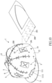
- FIG. 1 is a perspective view to show the hat of the present invention
- FIG. 2 is another perspective view to show the hat of the present invention
- FIG. 3 shows that the main part is integral with the base plate
- FIG. 4 shows that the main part is separated from the base plate
- FIG. 5 shows that the ropes extend through the main part of the hat of the present invention
- FIG. 6 shows another status of the hat wherein the ropes extend through the main part and the visor of the hat of the present invention
- FIG. 7 shows that a child wears the hat of the present invention
- FIG. 8 shows that the two ends of the main part are cut to adjust the size of the hat
- FIG. 9 shows that the hat of the present invention includes a strap
- FIG. 10 shows that the hat of the present invention includes soft pads attached thereon
- FIG. 11 shows the drawing area on the hat of the present invention.
- the hat of the present invention comprises a main part 1 which is a planar part and made of soft material such as silicon rubber and foam rubber to absorb shocks.
- the main part 1 includes a visor 11 , a peripheral portion 12 and multiple panels 15 formed thereto.
- the peripheral portion 12 is an elongate portion which is circled to form an insert entrance 13 from which the wearer's head is inserted into the hat.
- the panels 15 extend from the top of the peripheral portion 12 .
- the width of each of the panels is gradually reduced from the root portion toward the tip portion thereof.
- the tip portion of each panels 15 is bent toward a top point 4 of the crown of the hat.
- the visor 11 is a curved plate which includes a curved outer side and an inner side. Two ends of the visor 11 are formed with the bottom side of the peripheral portion 12 .
- a protrusion 111 protrudes from the inner side of the visor 11 and toward the peripheral portion 12 . The protrusion 111 is bent to contact the outside of the peripheral portion 12 .
- Multiple first holes 5 are respectively defined through each of two lateral sides of each panel 15 , the bottom side of the peripheral portion 12 and the inner side of the visor 11 .
- the first holes 5 can be made by punching machine or made manually.
- Multiple ropes 6 extends through the first holes 5 to connect the panels 15 , the peripheral portion 12 and the visor 11 to form the hat.
- the present invention also provide a method for assembling a hat, and comprises the following steps:
- a step of separation removing a main part 1 from a base plate 100 as shown in FIGS. 3 and 4 ;
- a step of measuring wrapping the peripheral portion 12 to a wearer's head and cutting two ends of the peripheral portion 12 , the two ends of the main part 1 being cut as shown in FIG. 8 if the length of the main part 1 is longer than the size of the wearer's head;
- a step of tying the panels circling the peripheral portion 12 to form an insert entrance 13 , the visor 11 located outside of the peripheral portion 12 , extending multiple ropes 6 through the first holes 5 of the panels 15 to assemble the panels 15 toward each other as shown in FIGS. 2 and 5 , bending the panels 15 to form a room 3 with the peripheral portion 12 shown in FIGS. 2 and 6 , and
- a step of tying the peripheral portion bending the visor 11 upward, bending the protrusion 111 upward relative to the visor 11 , the protrusion 111 contacting outside of the peripheral portion 12 as shown in FIG. 6 , extending the ropes 6 through the first holes 5 of the peripheral portion 12 , the first holes 5 of the visor 11 and, the first holes 5 of the protrusion 111 to maintain the visor 11 to be an angle relative to the peripheral portion 12 as shown in FIG. 1 to form the hat.
- step of tying the peripheral portion is alternatively proceeded before the step of tying the panels or the step of measuring.
- the ropes 6 can be helped by adults or parents to finish.
- the hat can be disassembled by removing the ropes 6 to form a planar main part 1 for convenience of storage. As shown in FIG. 7 , the soft material of the main part 1 absorbs shocks to protect the child wearing the hat.
- the protrusion 111 makes the visor 11 to be protruded forward.
- the protrusion 111 contacts the outside of the peripheral portion 12 ensures that the visor 11 does not flip upward when an impact is applied to the visor 11 from the bottom.
- FIG. 8 shows that the two ends of the main part are cut along the dotted lines to adjust the room 3 of the hat.
- the hat may include a strap 7 and a chin pad 71 .
- the chin pad 71 includes two passages 8 through which the strap 7 extends.
- Two second holes 14 are respectively defined through the peripheral portion 12 diametrically. The two ends of the strap 7 are tied to the two second holes 14 .
- the method mentioned above further comprises a step of tying the strap: forming the base plate 100 with the chin pad 71 which has the two passages 8 , the strap 7 extending through the two passages 8 , the two second holes 14 respectively defined through the peripheral portion 12 diametrically, two ends of the strap 7 being tied to the two second holes 14 .
- the strap 7 ensures that the hat is worn in a stable status on the wear's head.
- the strap 7 is made of flexible material which is adjustable for different wearers.
- the main part 1 includes a drawing area 9 on the outside thereof.
- the method mentioned above further comprises a step of drawing: forming the drawing area 9 on the outside surface of the base plate 1 , using coloring tools to draw figures or color onto the drawing area 9 .
- the multiple apertures 16 are defined through either of the panels 15 or the peripheral portion 12 , or the multiple apertures 16 are defined through both of the panels 15 and the peripheral portion 12 .
- multiple soft pads 200 are connected to outside of either of the panels 15 or the peripheral portion 12 , or the multiple soft pads 200 are connected to the outside of both of the panels 15 and the peripheral portion 12 .
- Each of the soft pads 200 includes multiple bores 201 , and the ropes 6 extend through the bores 201 and tie to the apertures 16 .
- the method mentioned above further comprises a step of reinforcing the hat: cutting multiple soft pads 200 from the base plate 100 , tying the soft pads 200 to either the peripheral portion 12 or the panels 15 , or tying the soft pads 200 to both the peripheral portion 12 and the panels 15 .
- the hat disclosed includes six apertures 16 in each panels 15 , and each soft pad 200 includes 4 bores 201 , so that the soft pads 200 can be attached to desired positions of the hat.
- a gap 1111 is formed between the visor 11 and the protrusion 111 .
- the gap 1111 allows the protrusion 111 easily to be bent.
Abstract
Description
Claims (10)
Applications Claiming Priority (2)
| Application Number | Priority Date | Filing Date | Title |
|---|---|---|---|
| TW109203429 | 2020-03-25 | ||
| TW109203429U TWM601557U (en) | 2020-03-25 | 2020-03-25 | Soft cap body structure |
Publications (2)
| Publication Number | Publication Date |
|---|---|
| US20210298405A1 US20210298405A1 (en) | 2021-09-30 |
| US11259585B2 true US11259585B2 (en) | 2022-03-01 |
Family
ID=72334087
Family Applications (1)
| Application Number | Title | Priority Date | Filing Date |
|---|---|---|---|
| US16/939,067 Active 2040-08-02 US11259585B2 (en) | 2020-03-25 | 2020-07-27 | Hat with flexible panels |
Country Status (5)
| Country | Link |
|---|---|
| US (1) | US11259585B2 (en) |
| JP (1) | JP3228855U (en) |
| DE (1) | DE202020104649U1 (en) |
| MY (1) | MY197180A (en) |
| TW (1) | TWM601557U (en) |
Cited By (1)
| Publication number | Priority date | Publication date | Assignee | Title |
|---|---|---|---|---|
| US20220264981A1 (en) * | 2018-06-01 | 2022-08-25 | New Vision Technologies, LLC | Headwear with a set of hair ports |
Families Citing this family (1)
| Publication number | Priority date | Publication date | Assignee | Title |
|---|---|---|---|---|
| US11844388B2 (en) * | 2021-09-17 | 2023-12-19 | Mark Pearse-Danker | Hood |
Citations (21)
| Publication number | Priority date | Publication date | Assignee | Title |
|---|---|---|---|---|
| US397065A (en) * | 1889-01-29 | William t | ||
| US919984A (en) * | 1908-11-12 | 1909-04-27 | Alma Webster Powell | Hat-saver and hand-bag. |
| US945268A (en) * | 1908-04-27 | 1910-01-04 | James F Dodd | Hat or cap. |
| US1056391A (en) * | 1911-03-11 | 1913-03-18 | Mary Ellen Baldwin | Bonnet. |
| US1531394A (en) * | 1922-01-11 | 1925-03-31 | Hart Henry Ridgeway | Water-polo cap |
| US1623768A (en) * | 1926-03-08 | 1927-04-05 | John I Williams | Fisherman's hat |
| US1684610A (en) * | 1927-10-08 | 1928-09-18 | Lela B Weir | Adjustable hat lining |
| US2172510A (en) * | 1938-07-21 | 1939-09-12 | Gilbert Jaccard E | Hat |
| US3072916A (en) * | 1960-04-25 | 1963-01-15 | Henderson Cleophus | Bandanna hat |
| USD350221S (en) * | 1992-12-18 | 1994-09-06 | Vans, Inc. | Hat |
| US6543061B1 (en) * | 2001-08-17 | 2003-04-08 | Sabrina Morgan | Head cover assembly |
| US7073207B2 (en) * | 2004-08-21 | 2006-07-11 | Dada Corp. | Cap linked by strings |
| USD541013S1 (en) * | 2005-07-29 | 2007-04-24 | Dada Corp. | Cap |
| USD558432S1 (en) * | 2005-09-08 | 2008-01-01 | Dada Corporation | Cap |
| USD600891S1 (en) * | 2008-03-10 | 2009-09-29 | Steven Sadamu Fountain | Baseball-style cap with laces |
| US7707657B2 (en) * | 2000-03-27 | 2010-05-04 | Dong Soo Kim | Headgear provided with a ponytail |
| USD638613S1 (en) * | 2010-07-08 | 2011-05-31 | Romo Caesar A | Hat |
| USD657117S1 (en) * | 2010-11-19 | 2012-04-10 | Joshua Burwell | Stitched baseball-style cap |
| USD797411S1 (en) * | 2015-02-06 | 2017-09-19 | Tevin Di Shon Shedd | Hat |
| US20190231013A1 (en) * | 2018-01-30 | 2019-08-01 | Jason Lamar Thomas | Headwear Apparatus that Matches to a Pair of Shoes |
| USD863733S1 (en) * | 2017-04-11 | 2019-10-22 | Kinga Konopka | Ball cap |
-
2020
- 2020-03-25 TW TW109203429U patent/TWM601557U/en unknown
- 2020-07-27 US US16/939,067 patent/US11259585B2/en active Active
- 2020-08-05 JP JP2020003311U patent/JP3228855U/en active Active
- 2020-08-06 MY MYPI2020004042A patent/MY197180A/en unknown
- 2020-08-11 DE DE202020104649.7U patent/DE202020104649U1/en active Active
Patent Citations (21)
| Publication number | Priority date | Publication date | Assignee | Title |
|---|---|---|---|---|
| US397065A (en) * | 1889-01-29 | William t | ||
| US945268A (en) * | 1908-04-27 | 1910-01-04 | James F Dodd | Hat or cap. |
| US919984A (en) * | 1908-11-12 | 1909-04-27 | Alma Webster Powell | Hat-saver and hand-bag. |
| US1056391A (en) * | 1911-03-11 | 1913-03-18 | Mary Ellen Baldwin | Bonnet. |
| US1531394A (en) * | 1922-01-11 | 1925-03-31 | Hart Henry Ridgeway | Water-polo cap |
| US1623768A (en) * | 1926-03-08 | 1927-04-05 | John I Williams | Fisherman's hat |
| US1684610A (en) * | 1927-10-08 | 1928-09-18 | Lela B Weir | Adjustable hat lining |
| US2172510A (en) * | 1938-07-21 | 1939-09-12 | Gilbert Jaccard E | Hat |
| US3072916A (en) * | 1960-04-25 | 1963-01-15 | Henderson Cleophus | Bandanna hat |
| USD350221S (en) * | 1992-12-18 | 1994-09-06 | Vans, Inc. | Hat |
| US7707657B2 (en) * | 2000-03-27 | 2010-05-04 | Dong Soo Kim | Headgear provided with a ponytail |
| US6543061B1 (en) * | 2001-08-17 | 2003-04-08 | Sabrina Morgan | Head cover assembly |
| US7073207B2 (en) * | 2004-08-21 | 2006-07-11 | Dada Corp. | Cap linked by strings |
| USD541013S1 (en) * | 2005-07-29 | 2007-04-24 | Dada Corp. | Cap |
| USD558432S1 (en) * | 2005-09-08 | 2008-01-01 | Dada Corporation | Cap |
| USD600891S1 (en) * | 2008-03-10 | 2009-09-29 | Steven Sadamu Fountain | Baseball-style cap with laces |
| USD638613S1 (en) * | 2010-07-08 | 2011-05-31 | Romo Caesar A | Hat |
| USD657117S1 (en) * | 2010-11-19 | 2012-04-10 | Joshua Burwell | Stitched baseball-style cap |
| USD797411S1 (en) * | 2015-02-06 | 2017-09-19 | Tevin Di Shon Shedd | Hat |
| USD863733S1 (en) * | 2017-04-11 | 2019-10-22 | Kinga Konopka | Ball cap |
| US20190231013A1 (en) * | 2018-01-30 | 2019-08-01 | Jason Lamar Thomas | Headwear Apparatus that Matches to a Pair of Shoes |
Cited By (2)
| Publication number | Priority date | Publication date | Assignee | Title |
|---|---|---|---|---|
| US20220264981A1 (en) * | 2018-06-01 | 2022-08-25 | New Vision Technologies, LLC | Headwear with a set of hair ports |
| US11464268B2 (en) * | 2018-06-01 | 2022-10-11 | New Vision Technologies, LLC | Headwear with a set of hair ports |
Also Published As
| Publication number | Publication date |
|---|---|
| JP3228855U (en) | 2020-11-12 |
| DE202020104649U1 (en) | 2020-08-19 |
| MY197180A (en) | 2023-05-30 |
| US20210298405A1 (en) | 2021-09-30 |
| TWM601557U (en) | 2020-09-21 |
Similar Documents
| Publication | Publication Date | Title |
|---|---|---|
| US11503872B2 (en) | Protective sports helmet | |
| US10376011B2 (en) | Football helmet with raised plateau | |
| US4682374A (en) | Protective ear covering | |
| US5794274A (en) | Chin protector for helmets | |
| US6349416B1 (en) | Headguard-protective sports headband | |
| EP1406519B1 (en) | Protective headgear | |
| US6266827B1 (en) | Impact protection headguard | |
| JP6016944B2 (en) | Helmet with adjustment device for helmet comfort liner | |
| US20120216339A1 (en) | Helmet with Shell Having Raised Central Channel | |
| US11388944B2 (en) | Chin strap | |
| US4463456A (en) | Protective helmet | |
| US11259585B2 (en) | Hat with flexible panels | |
| US5911308A (en) | Sports safety mask | |
| US20120047636A1 (en) | Sports helmet | |
| JP2007518888A (en) | Helmet fit elements | |
| US20230337777A1 (en) | Soft shell helmet | |
| US20060053521A1 (en) | Baseball catcher's mask | |
| US20190216155A1 (en) | Protective soft helmet | |
| EP1008370A1 (en) | New structural design for swimming goggles | |
| US6058516A (en) | Protective headgear for wrestlers | |
| US6564395B2 (en) | Wrestler headgear | |
| CN210696153U (en) | Internal buffer structure of helmet | |
| US7739752B2 (en) | Headgear | |
| US11730222B2 (en) | Helmet padding system | |
| KR20030010919A (en) | Helmet |
Legal Events
| Date | Code | Title | Description |
|---|---|---|---|
| FEPP | Fee payment procedure |
Free format text: ENTITY STATUS SET TO UNDISCOUNTED (ORIGINAL EVENT CODE: BIG.); ENTITY STATUS OF PATENT OWNER: MICROENTITY |
|
| FEPP | Fee payment procedure |
Free format text: ENTITY STATUS SET TO MICRO (ORIGINAL EVENT CODE: MICR); ENTITY STATUS OF PATENT OWNER: MICROENTITY Free format text: ENTITY STATUS SET TO UNDISCOUNTED (ORIGINAL EVENT CODE: BIG.); ENTITY STATUS OF PATENT OWNER: MICROENTITY |
|
| FEPP | Fee payment procedure |
Free format text: ENTITY STATUS SET TO UNDISCOUNTED (ORIGINAL EVENT CODE: BIG.); ENTITY STATUS OF PATENT OWNER: MICROENTITY |
|
| FEPP | Fee payment procedure |
Free format text: ENTITY STATUS SET TO MICRO (ORIGINAL EVENT CODE: MICR); ENTITY STATUS OF PATENT OWNER: MICROENTITY |
|
| STPP | Information on status: patent application and granting procedure in general |
Free format text: DOCKETED NEW CASE - READY FOR EXAMINATION |
|
| STPP | Information on status: patent application and granting procedure in general |
Free format text: NON FINAL ACTION MAILED |
|
| STPP | Information on status: patent application and granting procedure in general |
Free format text: RESPONSE TO NON-FINAL OFFICE ACTION ENTERED AND FORWARDED TO EXAMINER |
|
| STPP | Information on status: patent application and granting procedure in general |
Free format text: EX PARTE QUAYLE ACTION MAILED |
|
| STPP | Information on status: patent application and granting procedure in general |
Free format text: RESPONSE TO EX PARTE QUAYLE ACTION ENTERED AND FORWARDED TO EXAMINER |
|
| STPP | Information on status: patent application and granting procedure in general |
Free format text: NOTICE OF ALLOWANCE MAILED -- APPLICATION RECEIVED IN OFFICE OF PUBLICATIONS |
|
| STCF | Information on status: patent grant |
Free format text: PATENTED CASE |