US11255152B2 - Drill hole inner tube plug - Google Patents
Drill hole inner tube plug Download PDFInfo
- Publication number
- US11255152B2 US11255152B2 US16/616,286 US201816616286A US11255152B2 US 11255152 B2 US11255152 B2 US 11255152B2 US 201816616286 A US201816616286 A US 201816616286A US 11255152 B2 US11255152 B2 US 11255152B2
- Authority
- US
- United States
- Prior art keywords
- plug
- hole
- rod string
- wedge
- inner core
- Prior art date
- Legal status (The legal status is an assumption and is not a legal conclusion. Google has not performed a legal analysis and makes no representation as to the accuracy of the status listed.)
- Expired - Fee Related
Links
Images


Classifications
-
- E—FIXED CONSTRUCTIONS
- E21—EARTH OR ROCK DRILLING; MINING
- E21B—EARTH OR ROCK DRILLING; OBTAINING OIL, GAS, WATER, SOLUBLE OR MELTABLE MATERIALS OR A SLURRY OF MINERALS FROM WELLS
- E21B33/00—Sealing or packing boreholes or wells
- E21B33/10—Sealing or packing boreholes or wells in the borehole
- E21B33/12—Packers; Plugs
- E21B33/1208—Packers; Plugs characterised by the construction of the sealing or packing means
-
- E—FIXED CONSTRUCTIONS
- E21—EARTH OR ROCK DRILLING; MINING
- E21B—EARTH OR ROCK DRILLING; OBTAINING OIL, GAS, WATER, SOLUBLE OR MELTABLE MATERIALS OR A SLURRY OF MINERALS FROM WELLS
- E21B33/00—Sealing or packing boreholes or wells
- E21B33/10—Sealing or packing boreholes or wells in the borehole
- E21B33/13—Methods or devices for cementing, for plugging holes, crevices or the like
- E21B33/138—Plastering the borehole wall; Injecting into the formation
-
- E—FIXED CONSTRUCTIONS
- E21—EARTH OR ROCK DRILLING; MINING
- E21B—EARTH OR ROCK DRILLING; OBTAINING OIL, GAS, WATER, SOLUBLE OR MELTABLE MATERIALS OR A SLURRY OF MINERALS FROM WELLS
- E21B33/00—Sealing or packing boreholes or wells
- E21B33/10—Sealing or packing boreholes or wells in the borehole
- E21B33/13—Methods or devices for cementing, for plugging holes, crevices or the like
- E21B33/14—Methods or devices for cementing, for plugging holes, crevices or the like for cementing casings into boreholes
Definitions
- the present invention relates to industrial drilling.
- the invention relates to drill hole plugs for use in diamond drilling.
- Van Ruth Plugs Prior art drill hole plugs are readily available in the diamond drilling industry and are known as “Van Ruth Plugs”. They are used for bridging off (or ‘plugging’) a hole at a selected depth. There is a requirement to bridge the hole whenever a wedge is being installed off the bottom of the hole or whenever a cement job must be performed off the bottom of the hole. On most holes drilled, the hole must be capped with a cement plug. Such capping requires firstly the installation of a Van Ruth plug, followed by the pumping of cement on top of the Van Ruth plug.
- Van Ruth Plug To install a Van Ruth Plug in any hole, the first thing required is to pull out all of the drill rods from the hole, remove the complete core barrel assembly from the bottom end of the drill rods, and install a rod shoe on the end of the rods. This is required because the Van Ruth plug will not fit through the core barrel assembly.
- Holes are drilled up to 2000 meters deep, but most commonly to a depth of 800-1000 meters. When drill rods must be pulled out to remove the core barrel, put on a rod shoe, and then trip the rods all the way back down to the bottom of the hole. For a 1000-meter hole, this may take approximately eight hours.
- a plug for plugging a diamond drill hole comprising a body component having proximal and distal ends; a compressible plunger component attached to the distal end of the body component by attachment means; a plurality of plug feet disposed radially around the body component; and a torsion spring disposed between each pair of adjacent plug feet.
- the attachment means may be external threads on the distal end of the body and corresponding internal threads on the plunger component.
- the plunger may be manufactured of a spongy cellular material and may be encased in a resilient material selected from the group of materials comprising urethane and rubber.
- the plug feet may be manufactured of a cast zinc alloy.
- the plug feet may be transitionable between a compressed delivery position encircling the proximal end of the body component inside an inner core tube, and an expanded plugging position encircling a medial portion of the body component external to the inner core tube.
- a method of performing a down-hole orientation correction of a drill hole during diamond drilling comprising the steps of retracting the inner tube from the drill hole using a wireline winch; loading the plug of claim 1 into the end of the inner tube; delivering the inner tube and plug assembly down-hole to a desired deviation depth; pumping water down the hole to expel the plug from the inner tube; pumping an epoxy bag down the hole, through the center of the rod string, until it hits the plug; extracting the rod string from the hole, leaving the plug and epoxy at the desired deviation depth; attaching a wedge to the bottom of the rod string and re-inserting the rod string into the hole; setting the azimuth and plunging the wedge into the epoxy, breaking the connection between the rod string and the wedge; removing the rod string; re-installing the drill bit and lowering it to the wedge; and commencing drilling.
- a method of bypassing an impassable zone during diamond drilling comprising the steps of retracting the inner tube from the drill hole using a wireline winch; loading the plug of claim 1 into the end of the inner tube; delivering the inner tube and plug assembly down-hole to a desired depth above the impassable zone; pumping water down the hole to expel the plug from the inner tube; pumping an epoxy bag down the hole, through the center of the rod string, until it hits the plug; extracting the rod string from the hole, leaving the plug and epoxy at the desired deviation depth; attaching a wedge to the bottom of the rod string and re-inserting the rod string into the hole; setting the azimuth and plunging the wedge into the epoxy, breaking the connection between the rod string and the wedge; removing the rod string; re-installing the drill bit and lowering it to the wedge; and commencing drilling.
- a method of completing a drill hole during diamond drilling comprising the steps of retracting the inner tube from the drill hole using a wireline winch; loading the plug of claim 1 into the end of the inner tube; delivering the inner tube and plug assembly down-hole to the bottom of the hole; pumping water down the hole to expel the plug from the inner tube; and pumping concrete down the hole onto the plug to seal off the hole.
- FIG. 1 is a bottom plan view of a first embodiment of the plug and inner tube assembly of the invention with the plug in a compressed position inside the inner tube;
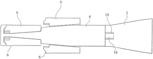
- FIG. 2 is a cross-sectional view through 2 — 2 of FIG. 1 showing the plug of the invention loaded inside the end of an inner tube;
- FIG. 3 is a bottom plan view of a first embodiment of the plug in an expanded position within the drill hole
- FIG. 4 is a cross-sectional view through 4 — 4 of FIG. 3 showing the plug of the invention expanded within the drill hole;
- FIG. 5A is a composite end plan view of FIGS. 1 and 3 for an alternate preferred second embodiment of the invention depicting the change in position of the plug feet between the compressed and expanded plug positions;
- FIG. 5B is a composite cross-sectional view of FIGS. 1 and 3 through 5B — 5 B of FIG. 5A ;
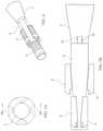
- FIG. 6 is a perspective view of the composite of FIGS. 5A and 5B ;
- FIG. 7 is a longitudinal cross-sectional view of a plug foot
- FIG. 8 is a horizontal cross-sectional view of a plug foot
- FIG. 9 is a plan view of a torsion spring
- FIG. 10 is a bottom plan view of the first embodiment of the plunger of the invention.
- FIG. 11 is a cross-sectional view of the plunger through 11 — 11 of FIG. 10 ;
- FIG. 12 is a bottom plan view of the first embodiment of the body of the plug of the invention.
- FIG. 13 is a cross-sectional view of the body of the plug through 13 — 13 of FIG. 12 .
- the plug of the present invention consists of 6 components, including the compressible plunger 2 which attaches to the main body 4 by threading on at the time of use.
- the main body houses the four plug feet 6 that are compressed into the reduced diameter and have a small torsion spring 8 between each adjacent pair of plug feet.
- the plunger preferably is manufactured of a dual density integral skin urethane foam.
- the plunger and body of the plug may be attached by a dowel 10 glued into corresponding openings 12 , 14 in the distal end of the body and the proximal end of the plunger.
- a dowel 10 glued into corresponding openings 12 , 14 in the distal end of the body and the proximal end of the plunger.
- an externally threaded projection 16 on the distal end of the body is threadable with an internally threaded receptacle 18 in the proximal end of the plunger.
- the plug of the present invention can be loaded inside of an inner core tube 20 before being pumped down the drill hole and ejected out the end of the core barrel without having to pull the drill rods out of the hole.
- This operation may require only 45 minutes for a drill hole 1000 meters deep. This is a very significant reduction in time and eliminates the wear and tear on the drill rod threads. By not having to make and break the joints, the wear and tear on the drill operators pulling the rods is eliminated, as is the risk associated with tripping “open” rods into the drill hole with only the rod shoe in place.
- the drill hole plug of the present invention was developed with the primary purpose of eliminating “rod tripping” when needing to install a bridging style plug.
- the plug of the present invention has a diameter sufficiently small as to fit within the inside of the inner core tube, there is no need to remove the core barrel assembly from the end of the drill rods and to install a rod shoe on the end of the drill rods.
- the other diamond drilling procedures that will benefit from the Inner Tube Plug of the present invention include situations where an impassable zone of rock is encountered that prevents the hole advancement. In these instances, the drill rods can be pulled back to a position higher up the hole and install an Inner Tube Plug and wedge to bypass this zone, eliminating one complete rod pulling cycle from this procedure as well.
- the inner tube and plug assembly of the present invention reduces the number of rod pulls required for setting a wedge, saving on time, fuel, people, and rod thread wear.
- the method of deployment of the plug of the present invention comprises the following steps:
- the inner tube drill plug apparatus and methods of the present invention are designed particularly for diamond drilling operations but use in other drilling operations may be possible with appropriate size customization.
Landscapes
- Life Sciences & Earth Sciences (AREA)
- Engineering & Computer Science (AREA)
- Geology (AREA)
- Mining & Mineral Resources (AREA)
- Physics & Mathematics (AREA)
- Environmental & Geological Engineering (AREA)
- Fluid Mechanics (AREA)
- General Life Sciences & Earth Sciences (AREA)
- Geochemistry & Mineralogy (AREA)
- Earth Drilling (AREA)
- Processing Of Stones Or Stones Resemblance Materials (AREA)
- Drilling Tools (AREA)
Abstract
Description
Claims (7)
Priority Applications (1)
| Application Number | Priority Date | Filing Date | Title |
|---|---|---|---|
| US16/616,286 US11255152B2 (en) | 2017-05-22 | 2018-05-22 | Drill hole inner tube plug |
Applications Claiming Priority (3)
| Application Number | Priority Date | Filing Date | Title |
|---|---|---|---|
| US201762509642P | 2017-05-22 | 2017-05-22 | |
| PCT/CA2018/000099 WO2018213917A1 (en) | 2017-05-22 | 2018-05-22 | Drill hole inner tube plug |
| US16/616,286 US11255152B2 (en) | 2017-05-22 | 2018-05-22 | Drill hole inner tube plug |
Publications (2)
| Publication Number | Publication Date |
|---|---|
| US20200224512A1 US20200224512A1 (en) | 2020-07-16 |
| US11255152B2 true US11255152B2 (en) | 2022-02-22 |
Family
ID=64395113
Family Applications (1)
| Application Number | Title | Priority Date | Filing Date |
|---|---|---|---|
| US16/616,286 Expired - Fee Related US11255152B2 (en) | 2017-05-22 | 2018-05-22 | Drill hole inner tube plug |
Country Status (7)
| Country | Link |
|---|---|
| US (1) | US11255152B2 (en) |
| AU (1) | AU2018272327B2 (en) |
| CA (1) | CA3064295A1 (en) |
| CL (1) | CL2019003417A1 (en) |
| MX (1) | MX2019013941A (en) |
| PE (1) | PE20200451A1 (en) |
| WO (1) | WO2018213917A1 (en) |
Citations (4)
| Publication number | Priority date | Publication date | Assignee | Title |
|---|---|---|---|---|
| US2978029A (en) * | 1959-05-11 | 1961-04-04 | Jersey Prod Res Co | Plug for well boreholes |
| US3760877A (en) * | 1969-02-26 | 1973-09-25 | Rech Activities Petrolieres En | Spoon for plugging cased petroleum production wells |
| US3776250A (en) * | 1972-04-13 | 1973-12-04 | Halliburton Co | Float collar with differential fill feature |
| US20140238694A1 (en) * | 2011-05-24 | 2014-08-28 | Smjm Limited | Support device for use in a wellbore and a method for deploying a barrier in a wellbore |
Family Cites Families (4)
| Publication number | Priority date | Publication date | Assignee | Title |
|---|---|---|---|---|
| US4378050A (en) * | 1981-01-28 | 1983-03-29 | Tatevosian Ruben A | Arrangement for full hole drilling |
| WO1998041811A1 (en) * | 1997-03-14 | 1998-09-24 | Silverport Pty. Ltd. | Device to facilitate the placing of slurries in up-holes |
| US7131504B2 (en) * | 2002-12-31 | 2006-11-07 | Weatherford/Lamb, Inc. | Pressure activated release member for an expandable drillbit |
| BR112013005961A2 (en) * | 2010-09-15 | 2016-05-03 | Rise Mining Developments Pty Ltd | mortar lid to plug a drill hole in a mine, clay lid to plug a drill hole, lid system to plug a drill hole and method of obstructing a drill hole in a mine |
-
2018
- 2018-05-22 CA CA3064295A patent/CA3064295A1/en active Pending
- 2018-05-22 AU AU2018272327A patent/AU2018272327B2/en active Active
- 2018-05-22 WO PCT/CA2018/000099 patent/WO2018213917A1/en not_active Ceased
- 2018-05-22 MX MX2019013941A patent/MX2019013941A/en unknown
- 2018-05-22 US US16/616,286 patent/US11255152B2/en not_active Expired - Fee Related
-
2019
- 2019-11-22 CL CL2019003417A patent/CL2019003417A1/en unknown
- 2019-12-09 PE PE2019002447A patent/PE20200451A1/en unknown
Patent Citations (4)
| Publication number | Priority date | Publication date | Assignee | Title |
|---|---|---|---|---|
| US2978029A (en) * | 1959-05-11 | 1961-04-04 | Jersey Prod Res Co | Plug for well boreholes |
| US3760877A (en) * | 1969-02-26 | 1973-09-25 | Rech Activities Petrolieres En | Spoon for plugging cased petroleum production wells |
| US3776250A (en) * | 1972-04-13 | 1973-12-04 | Halliburton Co | Float collar with differential fill feature |
| US20140238694A1 (en) * | 2011-05-24 | 2014-08-28 | Smjm Limited | Support device for use in a wellbore and a method for deploying a barrier in a wellbore |
Also Published As
| Publication number | Publication date |
|---|---|
| CL2019003417A1 (en) | 2020-05-04 |
| MX2019013941A (en) | 2020-07-20 |
| PE20200451A1 (en) | 2020-03-02 |
| CA3064295A1 (en) | 2018-11-29 |
| WO2018213917A1 (en) | 2018-11-29 |
| US20200224512A1 (en) | 2020-07-16 |
| AU2018272327A1 (en) | 2020-01-16 |
| AU2018272327B2 (en) | 2024-08-01 |
Similar Documents
| Publication | Publication Date | Title |
|---|---|---|
| RU2289018C2 (en) | Method for expansion of tubular element in well borehole | |
| RU2553717C2 (en) | Soluble bridge plug | |
| US7210533B2 (en) | Disposable downhole tool with segmented compression element and method | |
| US9518440B2 (en) | Bridge plug with selectivity opened through passage | |
| US10450846B2 (en) | Hybrid push and pull method and system for expanding well tubulars | |
| CN102414396A (en) | friction anchor | |
| CN107429555A (en) | Disintegration compression set connector with short mandrel | |
| RU2278941C2 (en) | Method and device for well drilling and anchor support fastening in borehole | |
| US12486753B2 (en) | Wellbore staged operation method and rubber plug for said method | |
| CN105239957A (en) | Expanded tube leaking stoppage device capable of being assembled and released | |
| US20110162846A1 (en) | Multiple Interval Perforating and Fracturing Methods | |
| NO346629B1 (en) | Burst port sub with dissolvable barrier | |
| US20220127812A1 (en) | Apparatus and method for fastening a composite pole to the ground | |
| CN108119107A (en) | Liner hanger sets instrument and its application method | |
| US8887807B2 (en) | Apparatus and methods for deploying cementing plugs | |
| CN106812530B (en) | Use the method for construction of protrusion fashioned iron supporting material and the steel pipe multistage tunnel of nose girder | |
| US11255152B2 (en) | Drill hole inner tube plug | |
| RU2410513C1 (en) | Method for multilateral well construction | |
| JP6521311B2 (en) | Chemical solution injection method under pressurized water | |
| JP6742755B2 (en) | Rock improvement rock bolt reinforcement method | |
| RU2626496C1 (en) | Plugs removing method from perforated shank holes while pumping horizontal well in bitumen deposit | |
| US20210355783A1 (en) | Method and apparatus for cementing a casing in a wellbore | |
| RU2563900C1 (en) | Multihole well construction method | |
| RU2501935C1 (en) | Repair method of casing string in well with defective section | |
| RU2242582C2 (en) | Device for pressurization of torn column in a well (variants) |
Legal Events
| Date | Code | Title | Description |
|---|---|---|---|
| FEPP | Fee payment procedure |
Free format text: ENTITY STATUS SET TO UNDISCOUNTED (ORIGINAL EVENT CODE: BIG.); ENTITY STATUS OF PATENT OWNER: SMALL ENTITY |
|
| FEPP | Fee payment procedure |
Free format text: ENTITY STATUS SET TO SMALL (ORIGINAL EVENT CODE: SMAL); ENTITY STATUS OF PATENT OWNER: SMALL ENTITY |
|
| STPP | Information on status: patent application and granting procedure in general |
Free format text: NON FINAL ACTION MAILED |
|
| STPP | Information on status: patent application and granting procedure in general |
Free format text: RESPONSE TO NON-FINAL OFFICE ACTION ENTERED AND FORWARDED TO EXAMINER |
|
| STPP | Information on status: patent application and granting procedure in general |
Free format text: AWAITING TC RESP., ISSUE FEE NOT PAID |
|
| STPP | Information on status: patent application and granting procedure in general |
Free format text: NOTICE OF ALLOWANCE MAILED -- APPLICATION RECEIVED IN OFFICE OF PUBLICATIONS |
|
| STCF | Information on status: patent grant |
Free format text: PATENTED CASE |
|
| FEPP | Fee payment procedure |
Free format text: MAINTENANCE FEE REMINDER MAILED (ORIGINAL EVENT CODE: REM.); ENTITY STATUS OF PATENT OWNER: SMALL ENTITY |
|
| LAPS | Lapse for failure to pay maintenance fees |
Free format text: PATENT EXPIRED FOR FAILURE TO PAY MAINTENANCE FEES (ORIGINAL EVENT CODE: EXP.); ENTITY STATUS OF PATENT OWNER: SMALL ENTITY |
|
| STCH | Information on status: patent discontinuation |
Free format text: PATENT EXPIRED DUE TO NONPAYMENT OF MAINTENANCE FEES UNDER 37 CFR 1.362 |
|
| FP | Lapsed due to failure to pay maintenance fee |
Effective date: 20260222 |