US11249111B2 - Automatic probe ground connection checking techniques - Google Patents
Automatic probe ground connection checking techniques Download PDFInfo
- Publication number
- US11249111B2 US11249111B2 US16/028,236 US201816028236A US11249111B2 US 11249111 B2 US11249111 B2 US 11249111B2 US 201816028236 A US201816028236 A US 201816028236A US 11249111 B2 US11249111 B2 US 11249111B2
- Authority
- US
- United States
- Prior art keywords
- ground
- probe
- oscilloscope
- dut
- test
- Prior art date
- Legal status (The legal status is an assumption and is not a legal conclusion. Google has not performed a legal analysis and makes no representation as to the accuracy of the status listed.)
- Active
Links
Images


Classifications
-
- G—PHYSICS
- G01—MEASURING; TESTING
- G01R—MEASURING ELECTRIC VARIABLES; MEASURING MAGNETIC VARIABLES
- G01R1/00—Details of instruments or arrangements of the types included in groups G01R5/00 - G01R13/00 and G01R31/00
- G01R1/02—General constructional details
- G01R1/06—Measuring leads; Measuring probes
- G01R1/067—Measuring probes
- G01R1/06788—Hand-held or hand-manipulated probes, e.g. for oscilloscopes or for portable test instruments
-
- G—PHYSICS
- G01—MEASURING; TESTING
- G01R—MEASURING ELECTRIC VARIABLES; MEASURING MAGNETIC VARIABLES
- G01R1/00—Details of instruments or arrangements of the types included in groups G01R5/00 - G01R13/00 and G01R31/00
- G01R1/02—General constructional details
- G01R1/06—Measuring leads; Measuring probes
- G01R1/067—Measuring probes
- G01R1/06766—Input circuits therefor
-
- G—PHYSICS
- G01—MEASURING; TESTING
- G01R—MEASURING ELECTRIC VARIABLES; MEASURING MAGNETIC VARIABLES
- G01R1/00—Details of instruments or arrangements of the types included in groups G01R5/00 - G01R13/00 and G01R31/00
- G01R1/02—General constructional details
- G01R1/06—Measuring leads; Measuring probes
- G01R1/067—Measuring probes
- G01R1/06794—Devices for sensing when probes are in contact, or in position to contact, with measured object
-
- G—PHYSICS
- G01—MEASURING; TESTING
- G01R—MEASURING ELECTRIC VARIABLES; MEASURING MAGNETIC VARIABLES
- G01R31/00—Arrangements for testing electric properties; Arrangements for locating electric faults; Arrangements for electrical testing characterised by what is being tested not provided for elsewhere
- G01R31/50—Testing of electric apparatus, lines, cables or components for short-circuits, continuity, leakage current or incorrect line connections
- G01R31/54—Testing for continuity
Definitions
- connection between an oscilloscope probe and a device under test is often unreliable due to motion of the probe, e.g., if held by hand, motion of the DUT, e.g., vibration or thermal expansion, or both.
- motion of the DUT e.g., vibration or thermal expansion, or both.
- the presence of a faulty connection for the “active” lead, e.g., signal lead of a probe to the DUT, is usually easy to determine if the registered signal is dramatically different from the expected signal.
- Oscilloscope users have traditionally dealt with this unreliability by either wiggling the probe to see if anything changes in the signal or temporarily disconnecting the probe from the oscilloscope and measuring the resistance from the probe ground to the DUT ground with an ohmmeter.
- Embodiments of the disclosed technology generally include an automated probe-to-DUT (device under test) connection verification that can be easily initiated through an oscilloscope user interface, e.g., by way of a button on the probe or oscilloscope front-panel, a menu entry, a remote command over a general purpose interface bus (GPIB) or local area network (LAN), automatically, or any combination thereof.
- an oscilloscope user interface e.g., by way of a button on the probe or oscilloscope front-panel, a menu entry, a remote command over a general purpose interface bus (GPIB) or local area network (LAN), automatically, or any combination thereof.
- GPSIB general purpose interface bus
- LAN local area network
- FIG. 1 illustrates an example of a testing system in accordance with certain embodiments of the disclosed technology.
- FIG. 2 illustrates an example of a first technique for checking a ground connection between an oscilloscope and a DUT, such as the oscilloscope and DUT of FIG. 1 , in accordance with certain embodiments of the disclosed technology.
- FIG. 3 illustrates an example of a second technique for checking a ground connection between an oscilloscope and a DUT, such as the oscilloscope and DUT of FIG. 1 , in accordance with certain embodiments of the disclosed technology.
- FIG. 4 illustrates an example of a third technique for checking a ground connection between an oscilloscope and a DUT, such as the oscilloscope and DUT of FIG. 1 , in accordance with certain embodiments of the disclosed technology.
- FIG. 5 illustrates an example of a fourth technique for checking a ground connection between an oscilloscope and a DUT in accordance with certain embodiments of the disclosed technology.
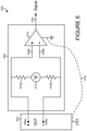
- FIG. 6 illustrates an example of a fifth technique for checking a ground connection between an oscilloscope and a DUT in accordance with certain embodiments of the disclosed technology.
- FIG. 7 illustrates an example of a sixth technique for checking a ground connection between an oscilloscope and a DUT, such as the oscilloscope and DUT of FIG. 1 , in accordance with certain embodiments of the disclosed technology.
- Embodiments of the disclosed technology generally include various techniques for automatically checking a ground connection between an oscilloscope and a device under test (DUT), e.g., within a probe and/or probe cable.
- DUT device under test
- FIG. 1 illustrates an example of a testing system 100 in accordance with certain embodiments of the disclosed technology.
- the testing system 100 includes an oscilloscope 102 , a DUT 104 , and a ground connection 106 between the oscilloscope 102 and the DUT 104 .
- the ground connection 106 is usually established by way of a probe and corresponding probe cable and/or other suitable connecting mechanism.
- the testing system 100 also includes an auxiliary ground 108 that exists due to indirect physical connections between the oscilloscope 102 and the DUT 104 , such as power-cord ground connections, ground connections of other probes, a table or other supporting structure, floor, etc. In certain systems, however, the auxiliary ground 108 is not present.
- FIG. 2 illustrates an example of a first technique 200 for checking a ground connection between an oscilloscope and a DUT, such as the oscilloscope 102 and the DUT 104 of FIG. 1 , in accordance with certain embodiments of the disclosed technology.
- the example includes a probe or probe cable 202 , such as a coaxial cable, that has a signal input 204 a , e.g., to receive an active signal from the DUT, a signal output 204 b , e.g., to provide the signal to the oscilloscope, an input ground 206 a , e.g., to connect to the DUT ground, and an output ground 206 b , e.g., to connect to the oscilloscope ground.
- a probe or probe cable 202 such as a coaxial cable, that has a signal input 204 a , e.g., to receive an active signal from the DUT, a signal output 204 b , e.g., to
- the first technique 200 includes the inductive coupling of a test coil 208 to the probe cable 202 by passing both through a magnetic core 210 and measuring the inductance of the test coil 208 , e.g., by way of an optional impedance meter 212 . This may be performed, for example, by injecting an alternating current therein and measuring the resulting voltage.
- a solid probe-to-DUT ground connection combined with another oscilloscope-to-DUT ground connection, e.g., power cords, may create a shorted loop through the magnetic core, thereby lowering the inductance of the test coil.
- test coil 208 and magnetic core 210 may be partially or fully integrated with the probe cable 202 or, alternatively, removably attachable thereto.
- the optional impedance meter 212 or other suitable measurement device may be integrated with or separate from either or both of the test coil 208 and magnetic core 210 .
- the illustrated technique 200 provides a number of advantages.
- the magnetic core 210 , test coil 208 , or combination thereof are generally easy to add to existing probe designs.
- the magnetic core 210 , test coil 208 , or combination thereof may be constructed as a separate accessory that may be used in connection with virtually any existing probe cable.
- the illustrated technique 200 is also advantageous in that such implementations generally do not interfere with the signal-path design of a probe. Further, verification of the ground connection may be performed without affecting active signal acquisitions, at least in situations where the connection is solid.
- FIG. 3 illustrates an example of a second technique 300 for checking a ground connection between an oscilloscope and a DUT, such as the oscilloscope 102 and the DUT 104 of FIG. 1 , in accordance with certain embodiments of the disclosed technology.
- the example includes a probe or probe cable 302 that has a signal input 304 a , e.g., to receive an active signal from the DUT, a signal output 304 b , e.g., to provide the signal to the oscilloscope, an input ground 306 a , e.g., to connect to the DUT ground, and an output ground 306 b , e.g., to connect to the oscilloscope ground.
- a signal input 304 a e.g., to receive an active signal from the DUT
- a signal output 304 b e.g., to provide the signal to the oscilloscope
- an input ground 306 a e.g., to connect to the DUT ground
- the technique 300 includes separating the input ground 306 a from the output ground 306 b , e.g., by way of a switch mechanism 308 , inserting a direct current into the input ground 306 a , and checking for a low DC resistance return path, e.g., through the probe-to-DUT ground connection and oscilloscope-to-DUT ground connection.
- the determination of a low DC resistance return path may indicate that the ground path within the probe cable 302 is functioning as expected, whereas a high DC resistance return path may indicate the presence of a disconnect or other issue with the probe ground path.
- the input ground 306 a and output ground 306 b may be AC coupled, e.g., by way of an optional capacitor 310 , to allow for AC signal current flow during the check for a low DC resistance return path.
- Capacitor 310 may also be useful in reducing the high-frequency impedance of the probe ground path due to inductance and/or resistance in the switch mechanism 308 .
- FIG. 4 illustrates an example of a third technique 400 for checking a ground connection between an oscilloscope and a DUT, such as the oscilloscope 102 and the DUT 104 of FIG. 1 , in accordance with certain embodiments of the disclosed technology.
- This example is similar to the example illustrated in FIG. 3 in that it includes a probe or probe cable 402 that has a signal input 404 a , e.g., to receive an active signal from the DUT, a signal output 404 b , e.g., to provide the signal to the oscilloscope, an input ground 406 a , e.g., to connect to the DUT ground, and an output ground 406 b , e.g., to connect to the oscilloscope ground.
- a probe or probe cable 402 that has a signal input 404 a , e.g., to receive an active signal from the DUT, a signal output 404 b , e.g., to provide the signal to the
- the technique 400 includes a buffer amplifier 408 and voltage source 410 , e.g., a DAC, between the input ground 406 a and the output ground 406 b rather than a switch mechanism separating the input ground 406 a from the output ground 406 b .
- the voltage source 410 can be programmed to drive the input ground [through the buffer amplifier 408 ] to 0.0 V, e.g. ground, for normal operation or to some non-zero voltage to check for a low-impedance path back to the scope ground through the auxiliary path. That is, this technique can check for an output current-limit condition in the buffer amplifier 408 to determine a low-resistance path.
- the example illustrated in FIG. 4 also includes a capacitor 412 in parallel with the buffer amplifier 408 and voltage source 410 .
- a determination may be made as to whether there is a disconnect or other issue with regard to the ground path within the probe cable 402 or the connection to the DUT ground at 406 a.
- the techniques 300 and 400 of FIGS. 3 and 4 provide various advantages.
- the physical implementations have the potential of being very small.
- the implementations of these techniques generally do not interfere with typical probe signal-path designs.
- probe ground path integrity verification can be typically performed without affecting active signal acquisitions, at least in situations where the connection is solid.
- FIG. 5 illustrates an example of a fourth technique 500 for checking a connection between an oscilloscope probe and a DUT in accordance with certain embodiments of the disclosed technology.
- the example includes a probe or probe cable 502 that has a signal input 504 a , e.g., to receive an active signal from the DUT, a signal output 504 b , e.g., to provide the signal to the oscilloscope, an input ground 506 a , e.g., to connect to the DUT ground, and an output ground 506 b , e.g., to connect to the oscilloscope ground.
- there is no auxiliary ground connection so the technique involves checking the DUT signal and ground connections as well as the DUT drive impedance.
- the example further includes a resistor 508 and a voltage source 510 such that the probe termination voltage may be adjusted. Once the voltage has been adjusted, a check may be made as to whether the calculated probe tip voltage stays relatively constant. A low-resistance drive generally indicates good connections, whereas a high-resistance drive generally indicates a bad connection, in which case the probe tip voltage may track the termination voltage.
- each pertinent termination voltage may be adjusted. If the termination voltages of the differential or tri-mode probe can be adjusted independently and/or the probe tip voltages measured independently, the two probe tip connections may be independently verified. Otherwise, a solid connection for both probe tips may still be simultaneously verified. Also, the differential probe tip signal connections can be verified with this technique independent of the absence or presence of an auxiliary ground connection.
- Implementations of this technique 500 are particularly advantageous in that they can be fully implemented as software for many existing probe designs that provide adjustable termination voltages, so there is no need for additional probe hardware to perform the ground checking.
- FIG. 6 illustrates an example of a fifth technique 600 for checking a connection between an oscilloscope probe and a DUT in accordance with certain embodiments of the disclosed technology.
- the example includes a probe or probe cable 604 configured to receive an input differential signal via DUT inputs 606 a and 608 a from DUT 602 and provide an output differential signal 616 , e.g., to an oscilloscope.
- the output differential signal 616 is generated by way of the input differential signal received from DUT inputs 606 a and 608 a being passed to internal circuitry 614 via internal inputs 606 b and 608 b .
- the probe 604 also includes resistors 610 a and 610 b and a voltage source 612 for adjusting the signal being passed to the internal circuitry 614 via the internal inputs 606 b and 608 b .
- This technique 600 is particularly advantageous in that it may be used to check for an intact differential connection, including differential ground path, regardless of whether an auxiliary ground connection 618 is present.
- FIG. 7 illustrates an example of a sixth technique 700 for checking a ground connection between a DUT 702 and an oscilloscope 704 in accordance with certain embodiments of the disclosed technology.
- the example is similar to the example illustrated in FIG. 5 in that it includes a probe or probe cable 706 , e.g., a de-embed probe, that has a signal input 708 a , e.g., to receive an active signal from the DUT 702 , a signal output 708 b , e.g., to provide the signal to the oscilloscope 704 , an input ground 710 a , e.g., to connect to the ground of the DUT 702 , and an output ground 710 b , e.g., to connect to the ground of the oscilloscope 704 .
- a probe or probe cable 706 e.g., a de-embed probe
- a sub-assembly including a switching mechanism 712 and two impedance elements 714 and 716 , where impedance element 716 represents the normal input impedance of the probe or probe cable 706 may be used to measure the source impedance driving the probe 706 .
- the measured source impedance may then be compared with the expected source impedance, e.g., as determined by knowledge of the DUT 702 .
- a substantially similar or identical match of the source impedance with the expected impedance generally indicates a good connection, whereas a mismatch generally indicates a disconnect or other issue with regard to the signal or ground connection between the DUT 702 and the probe or probe cable 706 .
- Implementations of this technique 700 are particularly advantageous in that, because they can be fully implemented as software, there is no need for additional probe hardware to perform the ground checking. Further, this technique 700 may be used to check both signal and ground lead connections, because a bad ground connection will generally be reflected in high source impedance for at least certain frequency bands.
- a communication may be issued based on the checking of the probe ground connection using any of the techniques described herein. For example, an alert may be issued responsive to a determination that a disconnect or other issue is or may be present within the probe ground connection. In certain embodiments where no such disconnect or other issue is detected within the probe ground connection, a notification may be issued to advise the user that the probe ground connection appears to be solid.
- An alert or notification such as those described above may include a visual indication, e.g., the lighting of an LED or issuing of a text-based or other type of message, an audible indication, e.g., a buzzing sound or other noise suitable to be heard by a user, or any suitable combination thereof.
- the alert or notification may be delivered to the user by way of the test measurement device itself, e.g., by way of an oscilloscope display.
Landscapes
- Physics & Mathematics (AREA)
- General Physics & Mathematics (AREA)
- Measuring Leads Or Probes (AREA)
- Testing Of Short-Circuits, Discontinuities, Leakage, Or Incorrect Line Connections (AREA)
Abstract
Description
Claims (8)
Priority Applications (2)
| Application Number | Priority Date | Filing Date | Title |
|---|---|---|---|
| US16/028,236 US11249111B2 (en) | 2012-10-11 | 2018-07-05 | Automatic probe ground connection checking techniques |
| US17/114,468 US11454651B2 (en) | 2012-10-11 | 2020-12-07 | Automatic probe ground connection checking techniques |
Applications Claiming Priority (3)
| Application Number | Priority Date | Filing Date | Title |
|---|---|---|---|
| US13/649,303 US9194888B2 (en) | 2012-10-11 | 2012-10-11 | Automatic probe ground connection checking techniques |
| US14/949,562 US10041975B2 (en) | 2012-10-11 | 2015-11-23 | Automatic probe ground connection checking techniques |
| US16/028,236 US11249111B2 (en) | 2012-10-11 | 2018-07-05 | Automatic probe ground connection checking techniques |
Related Parent Applications (1)
| Application Number | Title | Priority Date | Filing Date |
|---|---|---|---|
| US14/949,562 Division US10041975B2 (en) | 2012-10-11 | 2015-11-23 | Automatic probe ground connection checking techniques |
Related Child Applications (1)
| Application Number | Title | Priority Date | Filing Date |
|---|---|---|---|
| US17/114,468 Division US11454651B2 (en) | 2012-10-11 | 2020-12-07 | Automatic probe ground connection checking techniques |
Publications (2)
| Publication Number | Publication Date |
|---|---|
| US20180313870A1 US20180313870A1 (en) | 2018-11-01 |
| US11249111B2 true US11249111B2 (en) | 2022-02-15 |
Family
ID=49447341
Family Applications (4)
| Application Number | Title | Priority Date | Filing Date |
|---|---|---|---|
| US13/649,303 Active 2033-04-17 US9194888B2 (en) | 2012-10-11 | 2012-10-11 | Automatic probe ground connection checking techniques |
| US14/949,562 Active 2032-12-26 US10041975B2 (en) | 2012-10-11 | 2015-11-23 | Automatic probe ground connection checking techniques |
| US16/028,236 Active US11249111B2 (en) | 2012-10-11 | 2018-07-05 | Automatic probe ground connection checking techniques |
| US17/114,468 Active US11454651B2 (en) | 2012-10-11 | 2020-12-07 | Automatic probe ground connection checking techniques |
Family Applications Before (2)
| Application Number | Title | Priority Date | Filing Date |
|---|---|---|---|
| US13/649,303 Active 2033-04-17 US9194888B2 (en) | 2012-10-11 | 2012-10-11 | Automatic probe ground connection checking techniques |
| US14/949,562 Active 2032-12-26 US10041975B2 (en) | 2012-10-11 | 2015-11-23 | Automatic probe ground connection checking techniques |
Family Applications After (1)
| Application Number | Title | Priority Date | Filing Date |
|---|---|---|---|
| US17/114,468 Active US11454651B2 (en) | 2012-10-11 | 2020-12-07 | Automatic probe ground connection checking techniques |
Country Status (4)
| Country | Link |
|---|---|
| US (4) | US9194888B2 (en) |
| EP (2) | EP2720047B1 (en) |
| JP (1) | JP6432928B2 (en) |
| CN (1) | CN103728525B (en) |
Families Citing this family (16)
| Publication number | Priority date | Publication date | Assignee | Title |
|---|---|---|---|---|
| US9194888B2 (en) * | 2012-10-11 | 2015-11-24 | Tektronix, Inc. | Automatic probe ground connection checking techniques |
| JP6062976B2 (en) * | 2015-02-18 | 2017-01-18 | アンリツ株式会社 | Ground connection failure detection device and ground connection failure detection method |
| US9933459B1 (en) * | 2016-11-11 | 2018-04-03 | Fluke Corporation | Magnetically coupled ground reference probe |
| LU100452B1 (en) * | 2017-09-22 | 2019-03-29 | Iee Sa | Method and System for Wire Interruption Detection for Guarded Sensors |
| EP3546975B1 (en) * | 2018-03-29 | 2024-09-04 | Rohde & Schwarz GmbH & Co. KG | Test arrangement and test method for characterizing a differential probe |
| US10551426B1 (en) * | 2018-08-23 | 2020-02-04 | Gregory Hubert Piesinger | Live URD cable elbow connectivity identification method and apparatus |
| US10886588B2 (en) | 2018-09-26 | 2021-01-05 | Keysight Technologies, Inc. | High dynamic range probe using pole-zero cancellation |
| CN109521232B (en) * | 2018-11-20 | 2023-09-19 | 闻泰通讯股份有限公司 | Oscilloscope probe auxiliary test device |
| US11486921B2 (en) * | 2020-04-03 | 2022-11-01 | International Business Machines Corporation | Protection adapter for oscilloscope probes |
| US12345755B2 (en) * | 2021-11-01 | 2025-07-01 | Tektronix, Inc. | Reverse recovery measurements and plots |
| EP4187260B1 (en) * | 2021-11-26 | 2025-11-12 | Sensepeek AB | Ground tuning switch |
| EP4273566B1 (en) * | 2022-05-03 | 2025-12-24 | IMS Gear SE & Co. KGaA | Electrical arrangement comprising a redundant electrical transmission path and means for detecting an error state thereof and method for detecting an error state of the redundant electrical transmission path of the electrical arrangement |
| CN115184844A (en) * | 2022-07-07 | 2022-10-14 | 国网江苏省电力有限公司电力科学研究院 | Method and device for live-line testing of connection state of single-ended grounding system of high-voltage cable |
| CN117761499A (en) * | 2022-09-19 | 2024-03-26 | 英业达科技有限公司 | Interleaved differential signal loop system and method |
| US20240377478A1 (en) * | 2023-05-08 | 2024-11-14 | Keithley Instruments, Llc | Apparatus and method for measuring contact resistance |
| CN116453582B (en) * | 2023-06-14 | 2023-09-22 | 合肥康芯威存储技术有限公司 | Signal testing system and method for memory |
Citations (15)
| Publication number | Priority date | Publication date | Assignee | Title |
|---|---|---|---|---|
| US4913153A (en) * | 1987-11-13 | 1990-04-03 | Florida International University | Personal dosimeter |
| US6064312A (en) * | 1998-07-31 | 2000-05-16 | Hewlett-Packard Company | Method and apparatus for automatic verification of measurement probe functionality and compensation |
| US20030189422A1 (en) * | 2002-04-05 | 2003-10-09 | Mctigue Michael T. | Apparatus and method for canceling DC errors and noise generated by ground shield current in a probe |
| US6836107B2 (en) * | 2002-11-22 | 2004-12-28 | Tektronix, Inc. | Constant input impedance AC coupling circuit for a current probe system |
| US6841986B1 (en) * | 2003-12-08 | 2005-01-11 | Dell Products L.P. | Inductively coupled direct contact test probe |
| US20060158798A1 (en) * | 2002-11-08 | 2006-07-20 | Jackson Jonathon K | Residual current devices |
| US20070143050A1 (en) * | 2005-12-15 | 2007-06-21 | International Business Machines Corporation | Method and apparatus for implementing automatic-calibration of TDR probing system |
| US20070257657A1 (en) * | 2006-05-08 | 2007-11-08 | Stevens Kerry A | Current probing system |
| US20090206859A1 (en) * | 2008-02-20 | 2009-08-20 | Agilent Technologies, Inc. | Probe device having a light source thereon |
| US20100118449A1 (en) * | 2007-03-02 | 2010-05-13 | Deepstream Technologies Ltd | Nulling current transformer |
| US9000776B1 (en) * | 2010-12-09 | 2015-04-07 | The United States Of America As Represented By The Secretary Of The Navy | Structure characteristic impedance estimator using current probe |
| US9194888B2 (en) * | 2012-10-11 | 2015-11-24 | Tektronix, Inc. | Automatic probe ground connection checking techniques |
| US9304150B2 (en) * | 2011-09-30 | 2016-04-05 | Keysight Technologies, Inc. | Closed core current probe |
| US20180306840A1 (en) * | 2017-04-21 | 2018-10-25 | Rohde & Schwarz Gmbh & Co. Kg | Adapter for a current probe and testing system |
| US20200295728A1 (en) * | 2019-03-12 | 2020-09-17 | Hioki E.E. Corporation | Current sensor and measurement device |
Family Cites Families (25)
| Publication number | Priority date | Publication date | Assignee | Title |
|---|---|---|---|---|
| US4646299A (en) * | 1983-08-01 | 1987-02-24 | Fairchild Semiconductor Corporation | Method and apparatus for applying and monitoring programmed test signals during automated testing of electronic circuits |
| US5293122A (en) * | 1992-06-08 | 1994-03-08 | Lecroy Corporation | Signal probe with remote control function |
| CN1023621C (en) * | 1992-06-22 | 1994-01-26 | 华北电力学院 | Detection method and detection device for ground fault in DC system |
| JPH08160097A (en) | 1994-12-05 | 1996-06-21 | Hitachi Ltd | Terminal block and control system using the same |
| JP3097896B2 (en) * | 1995-10-05 | 2000-10-10 | 日本電信電話株式会社 | Wiring current route search method |
| CN2305678Y (en) * | 1997-05-07 | 1999-01-27 | 崔英彦 | Descriminator for fault cable |
| US6351112B1 (en) | 1998-08-31 | 2002-02-26 | Agilent Technologies, Inc. | Calibrating combinations of probes and channels in an oscilloscope |
| US6725170B1 (en) | 2000-11-22 | 2004-04-20 | Tektronix, Inc. | Smart probe apparatus and method for automatic self-adjustment of an oscilloscope's bandwidth |
| CN2466669Y (en) * | 2001-02-19 | 2001-12-19 | 刘世春 | Multifunctional Cable Fault Detector |
| WO2003058260A1 (en) | 2002-01-07 | 2003-07-17 | Capres A/S | Electrical feedback detection system for multi-point probes |
| GB2386977A (en) | 2002-03-25 | 2003-10-01 | Sony Uk Ltd | API for access to content via metadata |
| US6856129B2 (en) * | 2002-07-09 | 2005-02-15 | Intel Corporation | Current probe device having an integrated amplifier |
| US20050185769A1 (en) * | 2004-02-25 | 2005-08-25 | Pickerd John J. | Calibration method and apparatus |
| US7049843B2 (en) * | 2004-03-10 | 2006-05-23 | Tektronix, Inc. | Signal acquisition probing system using a micro-cavity laser capable of sensing DC voltages |
| US7162375B2 (en) | 2005-02-04 | 2007-01-09 | Tektronix, Inc. | Differential termination and attenuator network for a measurement probe having an automated common mode termination voltage generator |
| US7167011B2 (en) * | 2005-05-27 | 2007-01-23 | Tektronix, Inc. | Differential measurement probe having retractable double cushioned variable spacing probing tips with EOS/ESD protection capabilities |
| KR100636680B1 (en) | 2005-06-29 | 2006-10-23 | 주식회사 하이닉스반도체 | Semiconductor device having recess gate and asymmetric impurity region and manufacturing method thereof |
| US7460983B2 (en) | 2006-08-23 | 2008-12-02 | Tektronix, Inc. | Signal analysis system and calibration method |
| US7518385B2 (en) * | 2006-06-29 | 2009-04-14 | Lecray Corporation | Probe using high pass ground signal path |
| US7414411B2 (en) | 2006-08-23 | 2008-08-19 | Tektronix, Inc. | Signal analysis system and calibration method for multiple signal probes |
| US7408363B2 (en) | 2006-08-23 | 2008-08-05 | Tektronix, Inc. | Signal analysis system and calibration method for processing acquires signal samples with an arbitrary load |
| JP5071086B2 (en) * | 2007-12-13 | 2012-11-14 | 横河電機株式会社 | Passive probe device |
| US8410804B1 (en) * | 2009-02-24 | 2013-04-02 | Keithley Instruments, Inc. | Measurement system with high frequency ground switch |
| TWI383160B (en) * | 2009-12-31 | 2013-01-21 | Test Research Inc | Electrical connection defect detection system and method |
| CN102385024A (en) * | 2011-10-11 | 2012-03-21 | 中国神华能源股份有限公司 | Equipment and method for detecting ground point of machine winding |
-
2012
- 2012-10-11 US US13/649,303 patent/US9194888B2/en active Active
-
2013
- 2013-10-10 EP EP13188180.7A patent/EP2720047B1/en active Active
- 2013-10-10 EP EP18209903.6A patent/EP3477308B1/en active Active
- 2013-10-11 JP JP2013213901A patent/JP6432928B2/en active Active
- 2013-10-11 CN CN201310471721.6A patent/CN103728525B/en active Active
-
2015
- 2015-11-23 US US14/949,562 patent/US10041975B2/en active Active
-
2018
- 2018-07-05 US US16/028,236 patent/US11249111B2/en active Active
-
2020
- 2020-12-07 US US17/114,468 patent/US11454651B2/en active Active
Patent Citations (17)
| Publication number | Priority date | Publication date | Assignee | Title |
|---|---|---|---|---|
| US4913153A (en) * | 1987-11-13 | 1990-04-03 | Florida International University | Personal dosimeter |
| US6064312A (en) * | 1998-07-31 | 2000-05-16 | Hewlett-Packard Company | Method and apparatus for automatic verification of measurement probe functionality and compensation |
| US20030189422A1 (en) * | 2002-04-05 | 2003-10-09 | Mctigue Michael T. | Apparatus and method for canceling DC errors and noise generated by ground shield current in a probe |
| US20060158798A1 (en) * | 2002-11-08 | 2006-07-20 | Jackson Jonathon K | Residual current devices |
| US6836107B2 (en) * | 2002-11-22 | 2004-12-28 | Tektronix, Inc. | Constant input impedance AC coupling circuit for a current probe system |
| US6841986B1 (en) * | 2003-12-08 | 2005-01-11 | Dell Products L.P. | Inductively coupled direct contact test probe |
| US20070143050A1 (en) * | 2005-12-15 | 2007-06-21 | International Business Machines Corporation | Method and apparatus for implementing automatic-calibration of TDR probing system |
| US20070257657A1 (en) * | 2006-05-08 | 2007-11-08 | Stevens Kerry A | Current probing system |
| US20100118449A1 (en) * | 2007-03-02 | 2010-05-13 | Deepstream Technologies Ltd | Nulling current transformer |
| US20090206859A1 (en) * | 2008-02-20 | 2009-08-20 | Agilent Technologies, Inc. | Probe device having a light source thereon |
| US9000776B1 (en) * | 2010-12-09 | 2015-04-07 | The United States Of America As Represented By The Secretary Of The Navy | Structure characteristic impedance estimator using current probe |
| US9304150B2 (en) * | 2011-09-30 | 2016-04-05 | Keysight Technologies, Inc. | Closed core current probe |
| US9194888B2 (en) * | 2012-10-11 | 2015-11-24 | Tektronix, Inc. | Automatic probe ground connection checking techniques |
| US10041975B2 (en) * | 2012-10-11 | 2018-08-07 | Tektronix, Inc. | Automatic probe ground connection checking techniques |
| US20210088553A1 (en) * | 2012-10-11 | 2021-03-25 | Tektronix, Inc. | Automatic Probe Ground Connection Checking Techniques |
| US20180306840A1 (en) * | 2017-04-21 | 2018-10-25 | Rohde & Schwarz Gmbh & Co. Kg | Adapter for a current probe and testing system |
| US20200295728A1 (en) * | 2019-03-12 | 2020-09-17 | Hioki E.E. Corporation | Current sensor and measurement device |
Non-Patent Citations (1)
| Title |
|---|
| European Patent Office, Extended European Search Report and Written Opinion for European Application No. 18209903.6, dated Apr. 1, 2019, 15 pages, Munich, Germany. |
Also Published As
| Publication number | Publication date |
|---|---|
| US20140103951A1 (en) | 2014-04-17 |
| EP3477308A1 (en) | 2019-05-01 |
| US11454651B2 (en) | 2022-09-27 |
| CN103728525A (en) | 2014-04-16 |
| US20210088553A1 (en) | 2021-03-25 |
| EP2720047B1 (en) | 2018-12-05 |
| JP6432928B2 (en) | 2018-12-05 |
| US9194888B2 (en) | 2015-11-24 |
| US10041975B2 (en) | 2018-08-07 |
| JP2014077795A (en) | 2014-05-01 |
| CN103728525B (en) | 2018-06-22 |
| EP2720047A1 (en) | 2014-04-16 |
| US20180313870A1 (en) | 2018-11-01 |
| EP3477308B1 (en) | 2023-08-30 |
| US20160077128A1 (en) | 2016-03-17 |
Similar Documents
| Publication | Publication Date | Title |
|---|---|---|
| US11454651B2 (en) | Automatic probe ground connection checking techniques | |
| US6864694B2 (en) | Voltage probe | |
| CN111693748B (en) | Current sensor and measuring device | |
| TWI582435B (en) | Dc-ac probe card topology | |
| CN110850334B (en) | Nondestructive testing method and device for CT secondary circuit state | |
| US11374402B2 (en) | Protection circuit for oscilloscope measurement channel | |
| WO2008143897A1 (en) | Transmission line pulse testing with reflection control | |
| CN101545962B (en) | Integral check system of FRA-type winding deformation tester | |
| JPH10142283A (en) | Monitoring system and electric contact system | |
| US20080001611A1 (en) | Probe using high pass ground signal path | |
| US9335364B2 (en) | SMU RF transistor stability arrangement | |
| CN110161383B (en) | Switch cabinet partial discharge detection device | |
| Matsushima et al. | Improvement of reproducibility of DPI method to quantify RF conducted immunity of LDO regulator | |
| US20180278043A1 (en) | Protection circuit for oscilloscope measurement channel | |
| CN209979842U (en) | Multi-channel test signal input device for sonar receiver | |
| CN221405763U (en) | Oscilloscope probe | |
| CN223488405U (en) | Audio filter testing device | |
| CN222070788U (en) | High-speed signal transmission interface short circuit detection device | |
| CN211878072U (en) | Voltage and current phase comparison circuit | |
| CN108235212A (en) | A kind of open detection circuit of horn circuit | |
| CN116184095A (en) | Electromagnetic Interference Injection Probes and Systems | |
| JPH11211791A (en) | Lsi tester |
Legal Events
| Date | Code | Title | Description |
|---|---|---|---|
| FEPP | Fee payment procedure |
Free format text: ENTITY STATUS SET TO UNDISCOUNTED (ORIGINAL EVENT CODE: BIG.); ENTITY STATUS OF PATENT OWNER: LARGE ENTITY |
|
| AS | Assignment |
Owner name: TEKTRONIX, INC, OREGON Free format text: ASSIGNMENT OF ASSIGNORS INTEREST;ASSIGNORS:KNIERIM, DANIEL G.;HAGERUP, WILLIAM A.;HICKMAN, BARTON T.;AND OTHERS;REEL/FRAME:046295/0689 Effective date: 20121011 |
|
| FEPP | Fee payment procedure |
Free format text: ENTITY STATUS SET TO SMALL (ORIGINAL EVENT CODE: SMAL); ENTITY STATUS OF PATENT OWNER: LARGE ENTITY Free format text: ENTITY STATUS SET TO UNDISCOUNTED (ORIGINAL EVENT CODE: BIG.); ENTITY STATUS OF PATENT OWNER: LARGE ENTITY |
|
| STPP | Information on status: patent application and granting procedure in general |
Free format text: DOCKETED NEW CASE - READY FOR EXAMINATION |
|
| STPP | Information on status: patent application and granting procedure in general |
Free format text: NON FINAL ACTION MAILED |
|
| STPP | Information on status: patent application and granting procedure in general |
Free format text: RESPONSE TO NON-FINAL OFFICE ACTION ENTERED AND FORWARDED TO EXAMINER |
|
| STPP | Information on status: patent application and granting procedure in general |
Free format text: FINAL REJECTION MAILED |
|
| STPP | Information on status: patent application and granting procedure in general |
Free format text: DOCKETED NEW CASE - READY FOR EXAMINATION |
|
| STPP | Information on status: patent application and granting procedure in general |
Free format text: NON FINAL ACTION MAILED |
|
| STPP | Information on status: patent application and granting procedure in general |
Free format text: RESPONSE TO NON-FINAL OFFICE ACTION ENTERED AND FORWARDED TO EXAMINER |
|
| STPP | Information on status: patent application and granting procedure in general |
Free format text: NOTICE OF ALLOWANCE MAILED -- APPLICATION RECEIVED IN OFFICE OF PUBLICATIONS |
|
| STPP | Information on status: patent application and granting procedure in general |
Free format text: PUBLICATIONS -- ISSUE FEE PAYMENT VERIFIED |
|
| STCF | Information on status: patent grant |
Free format text: PATENTED CASE |
|
| MAFP | Maintenance fee payment |
Free format text: PAYMENT OF MAINTENANCE FEE, 4TH YEAR, LARGE ENTITY (ORIGINAL EVENT CODE: M1551); ENTITY STATUS OF PATENT OWNER: LARGE ENTITY Year of fee payment: 4 |