US11246129B2 - Method for transmitting signal, network device and terminal device - Google Patents
Method for transmitting signal, network device and terminal device Download PDFInfo
- Publication number
- US11246129B2 US11246129B2 US16/667,763 US201916667763A US11246129B2 US 11246129 B2 US11246129 B2 US 11246129B2 US 201916667763 A US201916667763 A US 201916667763A US 11246129 B2 US11246129 B2 US 11246129B2
- Authority
- US
- United States
- Prior art keywords
- time
- domain resource
- synchronization signal
- transmitted
- signal block
- Prior art date
- Legal status (The legal status is an assumption and is not a legal conclusion. Google has not performed a legal analysis and makes no representation as to the accuracy of the status listed.)
- Active, expires
Links
Images


Classifications
-
- H—ELECTRICITY
- H04—ELECTRIC COMMUNICATION TECHNIQUE
- H04W—WIRELESS COMMUNICATION NETWORKS
- H04W48/00—Access restriction; Network selection; Access point selection
- H04W48/08—Access restriction or access information delivery, e.g. discovery data delivery
- H04W48/12—Access restriction or access information delivery, e.g. discovery data delivery using downlink control channel
-
- H—ELECTRICITY
- H04—ELECTRIC COMMUNICATION TECHNIQUE
- H04W—WIRELESS COMMUNICATION NETWORKS
- H04W72/00—Local resource management
- H04W72/04—Wireless resource allocation
- H04W72/044—Wireless resource allocation based on the type of the allocated resource
-
- H—ELECTRICITY
- H04—ELECTRIC COMMUNICATION TECHNIQUE
- H04W—WIRELESS COMMUNICATION NETWORKS
- H04W56/00—Synchronisation arrangements
-
- H—ELECTRICITY
- H04—ELECTRIC COMMUNICATION TECHNIQUE
- H04J—MULTIPLEX COMMUNICATION
- H04J11/00—Orthogonal multiplex systems, e.g. using WALSH codes
- H04J11/0069—Cell search, i.e. determining cell identity [cell-ID]
- H04J11/0073—Acquisition of primary synchronisation channel, e.g. detection of cell-ID within cell-ID group
-
- H—ELECTRICITY
- H04—ELECTRIC COMMUNICATION TECHNIQUE
- H04J—MULTIPLEX COMMUNICATION
- H04J11/00—Orthogonal multiplex systems, e.g. using WALSH codes
- H04J11/0069—Cell search, i.e. determining cell identity [cell-ID]
- H04J11/0076—Acquisition of secondary synchronisation channel, e.g. detection of cell-ID group
-
- H—ELECTRICITY
- H04—ELECTRIC COMMUNICATION TECHNIQUE
- H04W—WIRELESS COMMUNICATION NETWORKS
- H04W56/00—Synchronisation arrangements
- H04W56/001—Synchronization between nodes
-
- H—ELECTRICITY
- H04—ELECTRIC COMMUNICATION TECHNIQUE
- H04W—WIRELESS COMMUNICATION NETWORKS
- H04W56/00—Synchronisation arrangements
- H04W56/001—Synchronization between nodes
- H04W56/0015—Synchronization between nodes one node acting as a reference for the others
-
- H04W72/042—
-
- H—ELECTRICITY
- H04—ELECTRIC COMMUNICATION TECHNIQUE
- H04W—WIRELESS COMMUNICATION NETWORKS
- H04W72/00—Local resource management
- H04W72/04—Wireless resource allocation
- H04W72/044—Wireless resource allocation based on the type of the allocated resource
- H04W72/0446—Resources in time domain, e.g. slots or frames
-
- H—ELECTRICITY
- H04—ELECTRIC COMMUNICATION TECHNIQUE
- H04W—WIRELESS COMMUNICATION NETWORKS
- H04W72/00—Local resource management
- H04W72/20—Control channels or signalling for resource management
- H04W72/23—Control channels or signalling for resource management in the downlink direction of a wireless link, i.e. towards a terminal
-
- H—ELECTRICITY
- H04—ELECTRIC COMMUNICATION TECHNIQUE
- H04W—WIRELESS COMMUNICATION NETWORKS
- H04W72/00—Local resource management
- H04W72/50—Allocation or scheduling criteria for wireless resources
- H04W72/53—Allocation or scheduling criteria for wireless resources based on regulatory allocation policies
Definitions
- Embodiments of the present application relate to the field of wireless communications, and in particular, to a method for transmitting a signal, a network device and a terminal device.
- LTE Long Term Evolution
- PSS Primary Synchronization Signal
- SSS Secondary Synchronization Signal
- an entire cell can be covered by different beams, where each beam covers a small range in the cell, and an effect of multiple beams covering the entire cell is achieved by temporal sweeping. Since different synchronization signal blocks (SS Blocks) can be transmitted on different beams, locations of time-domain resources occupied by the synchronization signal blocks during transmission can be flexibly changed.
- SS Blocks synchronization signal blocks
- the embodiments of the present disclosure provide a method for transmitting a signal, a network device and a terminal device, which can effectively indicate locations of time-domain resources for transmitting synchronization signal blocks.
- a first aspect provides a method for transmitting a signal, including:
- transmission information of a synchronization signal block where the transmission information includes information on the number m of the synchronization signal block, and information on a time-domain resource set over which the m synchronization signal block is transmitted, where the time-domain resource set includes m time-domain resource units over which the m synchronization signal block is transmitted, and locations of m time-domain resource units in different time-domain resource sets are not completely the same, where m is a positive integer; and transmitting, by the network device, the transmission information to a terminal device, so that the terminal device receives, according to the transmission information, the m synchronization signal block transmitted by the network device.
- the network device when transmitting the synchronization signal blocks, the network device indicates the number of the synchronization signal blocks and corresponding specific time-domain locations to the terminal device, thereby an indication of the locations of the time-domain resources of the synchronization signal blocks can be achieved using few bits and the signaling overhead is reduced.
- ⁇ log 2 (n) ⁇ represents the number of bits occupied by the information on the time-domain resource set in the transmission information
- n represents the number of multiple time-domain resource sets over which the m synchronization signal block is capable of being transmitted
- n is a positive integer
- n C k m , k represents the number of time-domain resource unit over which the m synchronization signal block is capable of being transmitted, k is a positive integer, and k m.
- location of the m time-domain resource unit in each of the time-domain resource sets among the multiple time-domain resource sets satisfies a first condition.
- the first condition is determined by the network device, or agreed by the network device and the terminal device in advance.
- the transmission information further includes resource configuration information, where the resource configuration information is configured to indicate the first condition that the locations of the m time-domain resource units in each of the time-domain resource sets should satisfy.
- the m time-domain resource units over which the m synchronization signal blocks are transmitted in each of the time-domain resource sets are continuous, or the m time-domain resource units over which the m synchronization signal blocks are transmitted in each of the time-domain resource sets are spaced by a fixed number of time-domain resource units.
- the fixed number is determined by the network device, or agreed by the network device and the terminal device in advance.
- each of the m time-domain resource units includes at least one symbol.
- the synchronization signal block includes at least one of the following signals: a primary synchronization signal (PSS), a secondary synchronization signal (SSS), and a physical broadcast channel (PBCH).
- PSS primary synchronization signal
- SSS secondary synchronization signal
- PBCH physical broadcast channel
- a second aspect provides a method for transmitting a signal, including:
- a terminal device receiving, by a terminal device, transmission information of a synchronization signal block transmitted by a network device, where the transmission information includes information on the number m of the synchronization signal block, and information on a time-domain resource set over which the m synchronization signal block is transmitted, where the time-domain resource set includes m time-domain resource units over which the m synchronization signal block is transmitted, and locations of m time-domain resource units in different time-domain resource sets are not completely the same, where m is a positive integer; and receiving, by the terminal device, the m synchronization signal block transmitted by the network device according to the transmission information.
- the terminal device when receiving the synchronization signal blocks, the terminal device obtains the number of the synchronization signal blocks and corresponding specific time-domain locations indicated by the terminal device, thereby the locations of the time-domain resources of the synchronization signal blocks can be obtained using few bits and the signaling overhead is reduced.
- ⁇ log 2 (n) ⁇ represents the number of bits occupied by the information on the time-domain resource set in the transmission information, where n represents the number of multiple time-domain resource sets over which the m synchronization signal block is capable of being transmitted, and n is a positive integer.
- n C k m , k represents the number of time-domain resource unit over which the m synchronization signal block is capable of being transmitted, k is a positive integer, and k m.
- location of the m time-domain resource unit in each of the time-domain resource sets among the multiple time-domain resource sets satisfies a first condition.
- the first condition is determined by the network device, or agreed by the terminal device and the network device in advance.
- the transmission information further includes resource configuration information, where the resource configuration information is configured to indicate the first condition that the locations of the m time-domain resource units in each of the time-domain resource sets should satisfy.
- the first condition includes: among k time-domain resource units over which m synchronization signal blocks are capable of being transmitted, the m time-domain resource units over which the m synchronization signal blocks are transmitted in each of the time-domain resource sets are continuous, or the m time-domain resource units over which the m synchronization signal blocks are transmitted in each of the time-domain resource sets are spaced by a fixed number of time-domain resource units.
- the fixed number is determined by the network device, or agreed by the network device and the terminal device in advance.
- each of the m time-domain resource units includes at least one symbol.
- the synchronization signal block includes at least one of the following signals: a primary synchronization signal (PSS), a secondary synchronization signal (SSS), and a physical broadcast channel (PBCH).
- PSS primary synchronization signal
- SSS secondary synchronization signal
- PBCH physical broadcast channel
- a third aspect provides a network device, and the network device may perform operations, in the first aspect or any optional implementation of the first aspect, of the network device.
- the network device may include modular units configured to perform the operations, in the first aspect or any possible implementation of the first aspect, of the network device.
- a fourth aspect provides a terminal device, and the terminal device may perform operations, in the second aspect or any optional implementation of the second aspect, of the terminal device.
- the terminal device may include modular units configured to perform the operations, in the second aspect or any possible implementation of the second aspect, of the terminal device.
- a fifth aspect provides a network device, and the network device includes: a processor, a transceiver and a memory.
- the processor, the transceiver, and the memory communicate with one another via internal connection paths.
- the memory is configured to store instructions
- the processor is configured to execute the instructions stored by the memory.
- the execution causes the network device to perform the method in the first aspect or any possible implementation of the first aspect, or the execution causes the network device to implement the network device provided by the third aspect.
- a sixth aspect provides a terminal device, and the terminal device includes: a processor, a transceiver, and a memory.
- the processor, the transceiver, and the memory communicate with one another through internal connection paths.
- the memory is configured to store instructions
- the processor is configured to execute the instructions stored by the memory.
- the execution causes the terminal device to perform the method in the second aspect or any possible implementation of the second aspect, or the execution causes the terminal device to implement the terminal device provided by the fourth aspect.
- a seventh aspect provides a computer readable storage medium, and the computer readable storage medium stores a program, and the program causes a network device to perform any one of the methods for transmitting a signal in the first aspect and various implementations thereof.
- An eighth aspect provides a computer readable storage medium, and the computer readable storage medium stores a program, and the program causes a terminal device to perform any one of the methods for transmitting a signal in the second aspect and various implementations thereof.
- a ninth aspect provides a system on chip, and the system on chip includes an input interface, an output interface, a processor, and a memory, where the processor is configured to execute instructions stored by the memory, and when the instructions are executed, the processor can implement any one of the methods in the foregoing first aspect and various implementations thereof.
- a tenth aspect provides a system on chip, and the system on chip includes an input interface, an output interface, a processor, and a memory, where the processor is configured to execute instructions stored by the memory, and when the instructions are executed, the processor can implement any one of the methods in the foregoing second aspect and various implementations thereof.
- FIG. 1 is a schematic structural diagram of an application scenario of embodiments of the present application.
- FIG. 2 is a schematic diagram of flexible transmission of synchronization signal blocks on different time-domain resource units.
- FIG. 3 is a schematic diagram of flexible transmission of synchronization signal blocks on different time-domain resource units.
- FIG. 4 is a schematic diagram of flexible transmission of synchronization signal blocks on different time-domain resource units.
- FIG. 5 is a flow interaction diagram of a method for transmitting a signal according to an embodiment of the present application.
- FIG. 6 is a schematic diagram of time-domain resources of synchronization signal blocks according to an embodiment of the present application.
- FIG. 7 is a schematic diagram of time-domain resources of synchronization signal blocks according to an embodiment of the present application.
- FIG. 8 is a schematic diagram of time-domain resources of synchronization signal blocks according to an embodiment of the present application.
- FIG. 9 is a schematic diagram of time-domain resources of synchronization signal blocks according to an embodiment of the present application.
- FIG. 10 is a schematic diagram of time-domain resources of synchronization signal blocks according to an embodiment of the present application.
- FIG. 11 is a schematic diagram of time-domain resources of synchronization signal blocks according to an embodiment of the present application.
- FIG. 12 is a schematic block diagram of a network device according to an embodiment of the present application.
- FIG. 13 is a schematic block diagram of a terminal device according to an embodiment of the present application.
- FIG. 14 is a schematic structural diagram of a network device according to an embodiment of the present application.
- FIG. 15 is a schematic structural diagram of a terminal device according to an embodiment of the present application.
- FIG. 16 is a schematic structural diagram of a system on chip according to an embodiment of the present application.
- GSM Global System of Mobile Communication
- CDMA Code Division Multiple Access
- WCDMA Wideband Code Division Multiple Access
- LTE Long Term Evolution
- FDD Frequency Division Duplex
- TDD Time Division Duplex
- UMTS Universal Mobile Telecommunication System
- the present application describes various embodiments in connection with a terminal device.
- the terminal device may also refer to a user equipment (UE), an access terminal, a user unit, a user station, a moving station, a mobile station, a remote station, a remote terminal, a mobile device, a user terminal, a terminal, a wireless communication device, and a user agent, or a user device.
- UE user equipment
- the access terminal may be a cellular phone, a cordless phone, a Session Initiation Protocol (SIP) phone, a Wireless Local Loop (WLL) station, a Personal Digital Assistant (PDA), a handheld device, a computing device with wireless communication function, or another processing device, vehicle-mounted device, wearable device connected to a wireless modem, a terminal device in a future 5G network, or a terminal device in a future evolved Public Land Mobile Network (PLMN) network, etc.
- SIP Session Initiation Protocol
- WLL Wireless Local Loop
- PDA Personal Digital Assistant
- the present application describes various embodiments in connection with a network device.
- the network device may be a device for communicating with the terminal device, for example, may be a Base Transceiver Station (BTS) in a GSM system or a CDMA, or may be a NodeB (NB) in a WCDMA system, or may be an Evolutional Node B (eNB or eNodeB) in an LTE system, or the network device may be a relay station, an access point, an vehicle-mounted device, a wearable device, or a network side device in a future 5G network or a network side device in a future evolved PLMN network, etc.
- BTS Base Transceiver Station
- NB NodeB
- eNB or eNodeB Evolutional Node B
- LTE Long Term Evolutional Node B
- FIG. 1 is a schematic structural diagram of an application scenario of embodiments of the present application.
- the communication system in FIG. 1 may include a network device 10 and a terminal device 20 .
- the network device 10 is configured to provide communication services for the terminal device 20 and access a core network.
- the terminal device 20 can access a network by searching for synchronization signals, broadcast signals, and the like transmitted by the network device 10 , thereby performing communication with the network.
- the arrows shown in FIG. 1 may represent uplink/downlink transmissions by a cellular link between the terminal device 20 and the network device 10 .
- the network in the embodiments of the present application may refer to a Public Land Mobile Network (PLMN) or a Device to Device (D2D) network or a Machine to Machine/Man (M2M) network or other networks
- PLMN Public Land Mobile Network
- D2D Device to Device
- M2M Machine to Machine/Man
- FIG. 1 is only a simplified schematic diagram of an example, and other terminal devices may also be included in the network, which are not shown in FIG. 1 .
- an entire cell can be covered by different beams, where each beam covers a small range in the cell, and an effect of multiple beams covering the entire cell is achieved by temporal sweeping.
- SS block synchronization signal block
- i synchronization signal block
- the synchronization signal blocks may occupy the first four time-domain resource units in a k time-domain resource units, and in the schematic diagram of transmission of synchronization signal blocks shown in FIG. 3 , the synchronization signal blocks occupy the first, the third, the fifth, and the seventh time-domain resource units of the k time-domain resource units, and in the schematic diagram of transmission of synchronization signal blocks shown in FIG. 4 , the synchronization signal blocks occupy the third, the fourth, the seventh and the eighth time-domain resource units of the k time-domain resource units. It can be seen that in the 5G system, the locations of time-domain resource units occupied by synchronization signal blocks have a certain flexibility.
- One way of effectively indicating the locations of time-domain resource units for transmitting synchronization signal blocks is to form a bitmap, with k bits, and each bit is used to indicate whether a synchronization signal block (SS block) is transmitted on its corresponding location of time-domain. It is thus possible to intuitively represent various possibilities of locations of time-domain resources of synchronization signal blocks.
- the signaling overhead of this method is extremely large, especially when the period of transmission of synchronization signal blocks is long, and the number of synchronization signal blocks transmitted in each period is small, which causes a waste of large amount of signaling.
- a bitmap with k bits may cause a great waste.
- time-domain resource unit in the embodiments of the present application includes at least one symbol such as a Orthogonal Frequency Division Multiplexing (OFDM) symbol, and one time slot may include one or more time-domain resource units, and one time-domain resource unit can transmit one synchronization signal block, which may occupy at least one symbol.
- OFDM Orthogonal Frequency Division Multiplexing
- the network device when transmitting the synchronization signal blocks, the network device indicates the number of the synchronization signal blocks and corresponding specific time-domain locations to the terminal device, thereby an indication of the locations of the time-domain resources of the synchronization signal blocks can be achieved using few bits and the signaling overhead is reduced.
- FIG. 5 is a flow interaction diagram of a method for transmitting a signal according to an embodiment of the present application.
- the network device in FIG. 5 may be, for example, the network device 10 in FIG. 1 .
- the terminal device in FIG. 5 may be, for example, the terminal device 20 in FIG. 1 .
- the method for transmitting a signal includes:
- the network device determines transmission information of a synchronization signal block.
- the transmission information includes information on the number m of the synchronization signal block and information on a time-domain resource set over which the m synchronization signal block is transmitted.
- ⁇ log 2 (n) ⁇ represents the number of bits occupied by the information on the time-domain resource set in the transmission information, where n represents the number of multiple time-domain resource sets over which the m synchronization signal block is capable of being transmitted, and locations of m time-domain resource units over which m synchronization signal blocks are transmitted in different time-domain resource sets are not completely the same, where m is a positive integer, and n is a positive integer.
- Each time-domain resource set in the multiple time-domain resource sets includes at least one time-domain resource unit.
- the time-domain resource unit includes at least one symbol.
- One synchronization signal block may be transmitted over one time-domain resource unit.
- the time-domain synchronization signal block includes at least one of the following signals: a primary synchronization signal (PSS), a secondary synchronization signal (SSS), and a physical broadcast channel (PBCH).
- PSS primary synchronization signal
- SSS secondary synchronization signal
- PBCH physical broadcast channel
- the synchronization signal block may include at least one of information such as PSS, SSS, PBCH, and DMRS (demodulation reference signal) for demodulating the PBCH.
- the information may be collectively referred to as one synchronization signal block, and the one synchronization signal occupies a certain number of symbols (here referred to as time-domain resource units) for transmission.
- the PBCH may carry a corresponding demodulation reference signal (DMRS).
- DMRS demodulation reference signal
- the transmission information of the synchronization signal blocks needs to be transmitted to the terminal device to indicate the number m of the synchronization signal block and the time-domain resource set over which the m synchronization signal block is transmitted, so that the terminal device can correctly receive the m synchronization signal block. If there are n possible time-domain resource sets over which the m synchronization signal block is capable of being transmitted, the number of bits occupied by the information of the time-domain resource set over which the m synchronization signal block is transmitted included in the transmission information is ⁇ log 2 (n) ⁇ .
- the location of m time-domain resource unit over which the m synchronization signal block is transmitted in each time-domain resource set and the location of the m time-domain resource unit over which the m synchronization signal block is transmitted in other time-domain resource set of the multiple time-domain resource sets are not completely the same.
- the n time-domain resource sets over which the synchronization signal block is capable of being transmitted include time-domain resource unit 1 to time-domain resource unit 8 , respectively, and each time-domain resource unit may include at least one symbol for transmitting the synchronization signal block.
- the terminal device Since the network device transmits the synchronization signal block to the terminal device on time-domain resource unit 1 , the terminal device can be indicated by the “001” that the synchronization signal block is located in the time domain resource unit 1 , that is, the information on the time-domain resource set included in the transmission information is “001”.
- n C k m , k represents the number of time-domain resource unit over which the m synchronization signal block is capable of being transmitted, k is a positive integer, and k m.
- the network device Since the network device transmits the synchronization signal blocks to the terminal device over time-domain resource unit 1 and time-domain resource unit 2 , it can be indicated to the terminal device that the synchronization signal blocks are located on time-domain resource unit 1 and time-domain resource unit 2 by “001”, that is, the information on the time-domain resource set included in the transmission information is “001”.
- location of the m time-domain resource unit over which the m synchronization signal block is transmitted in each of the time-domain resource sets among the multiple time-domain resource sets satisfies a first condition.
- the first condition is determined by the network device and indicated to the terminal device, or agreed by the network device and the terminal device in advance, for example, specified in a protocol.
- the location of the m time-domain resource unit over which the m synchronization signal block is transmitted in each of the time-domain resource sets satisfies the first condition.
- the first condition is, for example, among k time-domain resource units over which m synchronization signal blocks are capable of being transmitted, the m time-domain resource units over which the m synchronization signal blocks are transmitted in each of the time-domain resource sets are continuous, or the m time-domain resource units over which the m synchronization signal blocks are transmitted in each of the time-domain resource sets are spaced by a fixed number of time-domain resource units.
- the fixed number is determined by the network device, or agreed by the network device and the terminal device in advance, for example, specified in the protocol.
- the “continuous” or “spaced” between the time-domain resource units herein is only for the time-domain resource units over which the synchronization signal block is transmitted in the multiple time-domain resource units. That is to say, there are no other time-domain resource units for transmitting synchronization signal blocks between the continuous m time-domain resource units, but the continuous m time-domain resource units may be spaced by time-domain resource units or symbols that are not used to transmit the synchronization signal blocks.
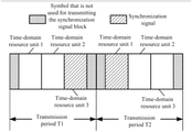
- each time-domain resource unit includes four symbols and is used to transmit one synchronization signal block.
- the time-domain resource unit 1 includes the second, the third, the fourth, and the fifth symbol
- the time-domain resource unit 2 includes the sixth, the seventh, the eighth, and the ninth symbol
- the time-domain resource unit 3 includes the tenth, eleventh, twelfth, and thirteenth symbol.
- the time-domain resource unit 3 in the transmission period T 1 and the time-domain resource unit 1 in the transmission period T 2 are continuous because the symbols 14 and 1 between the time-domain resource unit 3 in the transmission period T 1 and the time-domain resource unit 1 in the transmission period T 2 are not used to transmit the synchronization signal blocks.
- the time-domain resource unit 3 in T 1 and the time-domain resource unit 1 in T 2 are continuous and can form a time-domain resource set for transmitting the synchronization signal blocks.
- the network device transmits the synchronization signal blocks to the terminal device over the time-domain resource unit 1 and the time-domain resource unit 2 , it can be indicated to the terminal device that the synchronization signal blocks are located on the time-domain resource unit 1 and the time-domain resource unit 2 by “01”, that is, the information on the time-domain resource set included in the transmission information is “01”.
- the transmission information further includes resource configuration information, where the resource configuration information is configured to indicate the first condition that the locations of the m time-domain resource units over which the m synchronization signal blocks are transmitted in each of the time-domain resource sets should satisfy.
- the locations of the m time-domain resource units over which the m synchronization signal blocks are transmitted in each time-domain resource set may be required to satisfy a certain condition, and it can be indicated to the terminal device through the resource configuration information that the network device specifically uses a time-domain resource set satisfying which condition when transmitting the synchronization signal block to the terminal device.
- the resource configuration information may be carried in the transmission information and transmitted to the terminal device together, so that the terminal device determines, according to the resource configuration information, the m time-domain resource unit over which the m synchronization signal block is transmitted according to the information of ⁇ log 2 (n) ⁇ bits for indicating the time-domain resource set, among the n time-domain resource sets corresponding to the resource configuration information.
- condition 1, condition 2, and condition 3 can be satisfied between the two time-domain resource units over which the two synchronization signal blocks are transmitted, among the multiple time-domain resource sets over which the two synchronization signal blocks are capable of being transmitted.
- the condition 1 is: the m time-domain resource units over which the m synchronization signal blocks are transmitted are continuous (transmission period of synchronization signal blocks can be spanned); the condition 2 is: the m time-domain resource units over which the m synchronization signal blocks are transmitted are continuous (transmission period of synchronization signal blocks cannot be spanned); the condition 3 is: the m time-domain resource units over which the m synchronization signal blocks are transmitted are spaced by k time-domain resource units (k is even).
- the first condition may also be: the m time-domain resource units over which the m synchronization signal blocks are transmitted in each time-domain resource set include specific symbols, for example, the time-domain resource set includes the first four symbols, the time-domain resource set includes the last four symbols, the time-domain resource set includes symbols of odd numbers, or the time-domain resource set includes symbols of even numbers, and the like.
- the present disclosure does not limit this.
- the network device when transmitting the synchronization signal blocks, the network device indicates the number of the synchronization signal blocks and corresponding specific time-domain locations to the terminal device, thereby an indication of the locations of the time-domain resources of the synchronization signal blocks can be achieved using few bits and the signaling overhead is reduced.
- the network device transmits the transmission information to the terminal device.
- the network device may transmit the transmission information to the terminal device, so that the terminal device receives, according to the transmission information, the m synchronization signal block transmitted by the network device over the time-domain resource over which the m synchronization signal block is transmitted.
- the terminal device receives the transmission information transmitted by the network device.
- the transmission information includes information on the number m of the synchronization signal block and information on the time-domain resource set over which the m synchronization signal block is transmitted.
- ⁇ log 2 (n) ⁇ represents the number of bits occupied by the information on the time-domain resource set in the transmission information
- n represents the number of multiple time-domain resource sets over which the m synchronization signal block is capable of being transmitted
- locations of the m time-domain resource units over which the m synchronization signal blocks are transmitted in different time-domain resource sets are not completely the same, where m is a positive integer, and n is a positive integer.
- Each time-domain resource set in the multiple time-domain resource sets includes at least one time-domain resource unit.
- the time-domain resource unit includes at least one symbol.
- One synchronization signal block may be transmitted over one time-domain resource unit.
- the time-domain synchronization signal block includes at least one of the following signals: a primary synchronization signal (PSS), a secondary synchronization signal (SSS), and a physical broadcast channel (PBCH).
- PSS primary synchronization signal
- SSS secondary synchronization signal
- PBCH physical broadcast channel
- the PBCH may carry a corresponding demodulation reference signal (DMRS).
- DMRS demodulation reference signal
- the terminal device receives the m synchronization signal block transmitted by the network device according to the transmission information.
- the specific process that the terminal device receives the m synchronization signal blocks transmitted by the network device over time-domain resources for transmitting the m synchronization signal blocks according to the transmission information may refer to the related description to 510 in FIG. 6 to FIG. 11 , which will not be repeated here for the sake of brevity.
- the terminal device when receiving the synchronization signal blocks, the terminal device obtains the number of the synchronization signal blocks and corresponding specific time-domain locations indicated by the terminal device, thereby the locations of the time-domain resources of the synchronization signal blocks can be obtained using few bits and the signaling overhead is reduced.
- the size of the sequence number of each of the foregoing processes does not mean an order of execution sequence, and the order of execution of each of the processes should be determined by its function and internal logic, and should not constitute any limitation to the implementation process of the embodiments of the present disclosure.
- FIG. 12 is a schematic block diagram of a network device 1200 according to an embodiment of the present disclosure. As shown in FIG. 12 , the network device 1200 includes a determining unit 1210 and a transmitting unit 1220 . Where:
- the determining unit 1210 is configured to determine transmission information of a synchronization signal block, where the transmission information includes information on the number m of the synchronization signal block, and information on a time-domain resource set over which the m synchronization signal block is transmitted, where the time-domain resource set includes m time-domain resource unit over which the m synchronization signal block is transmitted, and locations of m time-domain resource units in different time-domain resource sets are not completely the same, where m is a positive integer; and
- the transmitting unit 1220 is configured to transmit the transmission information determined by the determining unit 1210 to a terminal device, so that the terminal device receives, according to the transmission information, the m synchronization signal block transmitted by the network device.
- the network device when transmitting the synchronization signal blocks, the network device indicates the number of the synchronization signal blocks and corresponding specific time-domain locations to the terminal device, thereby an indication of the locations of the time-domain resources of the synchronization signal blocks can be achieved using few bits and the signaling overhead is reduced.
- ⁇ log 2 (n) ⁇ represents the number of bits occupied by the information on the time-domain resource set in the transmission information, where n represents the number of multiple time-domain resource sets over which the m synchronization signal block is capable of being transmitted, and n is a positive integer.
- n C k m , k represents the number of time-domain resource unit over which the m synchronization signal block is capable of being transmitted, k is a positive integer, and k m.
- location of time-domain resource unit in each of the time-domain resource sets among the multiple time-domain resource sets satisfies a first condition.
- the first condition is determined by the network device, or agreed by the network device and the terminal device in advance.
- the transmission information further includes resource configuration information, where the resource configuration information is configured to indicate the first condition that the locations of the m time-domain resource units in each of the time-domain resource sets should satisfy.
- the first condition includes: among k time-domain resource units over which m synchronization signal blocks are capable of being transmitted, the m time-domain resource units over which the m synchronization signal blocks are transmitted in each of the time-domain resource sets are continuous, or the m time-domain resource units over which the m synchronization signal blocks are transmitted in each of the time-domain resource sets are spaced by a fixed number of time-domain resource units.
- the fixed number is determined by the network device, or agreed by the network device and the terminal device in advance.
- each of the m time-domain resource units includes at least one symbol.
- the synchronization signal block includes at least one of the following signals: a primary synchronization signal (PSS), a secondary synchronization signal (SSS), and a physical broadcast channel (PBCH).
- PSS primary synchronization signal
- SSS secondary synchronization signal
- PBCH physical broadcast channel
- FIG. 13 is a schematic block diagram of a terminal device 1300 according to an embodiment of the present disclosure. As shown in FIG. 13 , the terminal device 1300 includes a receiving unit 1310 .
- the receiving unit 1310 is configured to receive transmission information of a synchronization signal block transmitted by a network device, where the transmission information includes information on the number m of the synchronization signal block, and information on a time-domain resource set over which the m synchronization signal block is transmitted, where the time-domain resource set includes m time-domain resource units over which the m synchronization signal block is transmitted, and locations of m time-domain resource units in different time-domain resource sets are not completely the same, where m is a positive integer; and
- the receiving unit 1310 is further configured to receive the m synchronization signal block transmitted by the network device according to the transmission information.
- the terminal device when receiving the synchronization signal blocks, the terminal device obtains the number of the synchronization signal blocks and corresponding specific time-domain locations indicated by the terminal device, thereby the locations of the time-domain resources of the synchronization signal blocks can be obtained using few bits and the signaling overhead is reduced.
- ⁇ log 2 (n) ⁇ represents the number of bits occupied by the information on the time-domain resource set in the transmission information, where n represents the number of multiple time-domain resource sets over which the m synchronization signal block is capable of being transmitted, and n is a positive integer.
- n C k m , k represents the number of time-domain resource unit over which the m synchronization signal block is capable of being transmitted, k is a positive integer, and k m.
- the first condition is determined by the network device, or agreed by the terminal device and the network device in advance.
- the transmission information further includes resource configuration information, where the resource configuration information is configured to indicate the first condition that the locations of the m time-domain resource units in each of the time-domain resource sets should satisfy.
- the first condition includes: among k time-domain resource units over which m synchronization signal blocks are capable of being transmitted, the m time-domain resource units over which the m synchronization signal blocks are transmitted in each of the time-domain resource sets are continuous, or the m time-domain resource units over which the m synchronization signal blocks are transmitted in each of the time-domain resource sets are spaced by a fixed number of time-domain resource units.
- the fixed number is determined by the network device, or agreed by the network device and the terminal device in advance.
- each of the m time-domain resource units includes at least one symbol.
- the synchronization signal block includes at least one of the following signals: a primary synchronization signal (PSS), a secondary synchronization signal (SSS), and a physical broadcast channel (PBCH).
- PSS primary synchronization signal
- SSS secondary synchronization signal
- PBCH physical broadcast channel
- FIG. 14 is a schematic structural diagram of a network device 1400 according to an embodiment of the present disclosure.
- the network device includes: a processor 1410 , a transceiver 1420 and a memory 1430 .
- the processor 1410 , the transceiver 1420 , and the memory 1430 communicate with one another via internal connection paths.
- the memory 1430 is configured to store instructions, and the processor 1410 is configured to execute the instructions stored in the memory 1430 to control the transceiver 1420 to receive a signal or transmit a signal.
- the processor 1410 is configured to determine transmission information of a synchronization signal block, where the transmission information includes information on the number m of the synchronization signal block, and information on a time-domain resource set over which the m synchronization signal block is transmitted, where the time-domain resource set includes m time-domain resource units over which the m synchronization signal block is transmitted, and locations of m time-domain resource units in different time-domain resource sets are not completely the same, where m is a positive integer.
- the transceiver 1420 is configured to transmit the transmission information determined by the processor 1410 to the terminal device, so that the terminal device receives the m synchronization signal block transmitted by the network device according to the transmission information.
- ⁇ log 2 (n) ⁇ represents the number of bits occupied by the information on the time-domain resource set in the transmission information, where n represents the number of multiple time-domain resource sets over which the m synchronization signal block is capable of being transmitted, and n is a positive integer.
- n C k m , k represents the number of time-domain resource unit over which the m synchronization signal block is capable of being transmitted, k is a positive integer, and k m.
- location of the m time-domain resource unit in each of the time-domain resource sets among the multiple time-domain resource sets satisfies a first condition.
- the first condition is determined by the network device, or agreed by the network device and the terminal device in advance.
- the transmission information further includes resource configuration information, where the resource configuration information is configured to indicate the first condition that the locations of the m time-domain resource units in each of the time-domain resource sets should satisfy.
- the first condition includes: among k time-domain resource units over which m synchronization signal blocks are capable of being transmitted, the m time-domain resource units over which the m synchronization signal blocks are transmitted in each of the time-domain resource sets are continuous, or the m time-domain resource units over which the m synchronization signal blocks are transmitted in each of the time-domain resource sets are spaced by a fixed number of time-domain resource units.
- the fixed number is determined by the network device, or agreed by the network device and the terminal device in advance.
- each of the m time-domain resource units includes at least one symbol.
- the synchronization signal block includes at least one of the following signals: a primary synchronization signal (PSS), a secondary synchronization signal (SSS), and a physical broadcast channel (PBCH).
- PSS primary synchronization signal
- SSS secondary synchronization signal
- PBCH physical broadcast channel
- the processor 1410 may be a central processing unit (CPU), and the processor 1410 may also be other general purpose processors, digital signal processors (DSPs), application specific integrated circuits (ASIC), field programmable gate array (FPGA) or other programmable logic devices, discrete gate or transistor logic devices, discrete hardware components, or the like.
- DSPs digital signal processors
- ASIC application specific integrated circuits
- FPGA field programmable gate array
- a general purpose processor may be a microprocessor or the processor may also be any conventional processor or the like.
- the memory 1430 may include a read only memory and a random access memory, and provides instructions and data to the processor 1410 .
- a portion of the memory 1430 may further include a non-volatile random access memory.
- the memory 1430 may also store information of device type.
- each step of the above methods may be completed by an integrated logic circuit of hardware or an instruction in a form of software in the processor 1410 .
- the steps of the method for transmitting a signal disclosed in the embodiments of the present disclosure may be directly performed by a hardware processor, or may be performed by a combination of hardware and software modules in the processor 1410 .
- the software modules may be located in a mature storage medium in the field such as a random access memory, a flash memory, a read only memory, a programmable read only memory or an electrically erasable programmable memory, a register, or the like.
- the storage medium is located in the memory 1430 , and the processor 1410 reads the information in the memory 1430 , and completes the steps of the above methods in conjunction with its hardware. To avoid repetition, it will not be described in detail here.
- the network device 1400 may correspond to the network device for performing the method 500 in the foregoing method 500 , and the network device 1200 according to the embodiment of the present disclosure, and each unit or module in the network device 1400 is used for performing the operations or processes performed by the network device in the above method 500 , respectively.
- each unit or module in the network device 1400 is used for performing the operations or processes performed by the network device in the above method 500 , respectively.
- detailed description thereof will be omitted.
- FIG. 15 is a schematic structural diagram of a terminal device 1500 according to an embodiment of the present disclosure.
- the terminal device includes: a processor 1510 , a transceiver 1520 and a memory 1530 .
- the processor 1510 , the transceiver 1520 , and the memory 1530 communicate with one another via internal connection paths.
- the memory 1530 is configured to store instructions, and the processor 1510 is configured to execute the instructions stored in the memory 1530 to control the transceiver 1520 to receive a signal or transmit a signal.
- the transceiver 1520 is configured to: receiving transmission information of a synchronization signal block transmitted by a network device, where the transmission information includes information on the number m of the synchronization signal block, and information on a time-domain resource set over which the m synchronization signal block is transmitted, where the time-domain resource set includes m time-domain resource units over which the m synchronization signal block is transmitted, and locations of m time-domain resource units in different time-domain resource sets are not completely the same, where m is a positive integer; and receiving the m synchronization signal blocks transmitted by the network device according to the transmission information.
- ⁇ log 2 (n) ⁇ represents the number of bits occupied by the information on the time-domain resource set in the transmission information, where n represents the number of multiple time-domain resource sets over which the m synchronization signal block is capable of being transmitted, and n is a positive integer.
- n C k m , k represents the number of time-domain resource unit over which the m synchronization signal block is capable of being transmitted, k is a positive integer, and k m.
- location of the m time-domain resource unit in each of the time-domain resource sets among the multiple time-domain resource sets satisfies a first condition.
- the first condition is determined by the network device, or agreed by the network device and the terminal device in advance.
- the transmission information further includes resource configuration information, where the resource configuration information is configured to indicate the first condition that the locations of the m time-domain resource units in each of the time-domain resource sets should satisfy.
- the first condition includes: among k time-domain resource units over which m synchronization signal blocks are capable of being transmitted, the m time-domain resource units over which the m synchronization signal blocks are transmitted in each of the time-domain resource sets are continuous, or the m time-domain resource units over which the m synchronization signal blocks are transmitted in each of the time-domain resource sets are spaced by a fixed number of time-domain resource units.
- the fixed number is determined by the network device, or agreed by the network device and the terminal device in advance.
- each of the m time-domain resource units includes at least one symbol.
- the synchronization signal block includes at least one of the following signals: a primary synchronization signal (PSS), a secondary synchronization signal (SSS), and a physical broadcast channel (PBCH).
- PSS primary synchronization signal
- SSS secondary synchronization signal
- PBCH physical broadcast channel
- the processor 1510 may be a central processing unit (CPU), and the processor 1510 may also be other general purpose processors, digital signal processors (DSPs), application specific integrated circuits (ASIC), field programmable gate array (FPGA) or other programmable logic devices, discrete gate or transistor logic devices, discrete hardware components, or the like.
- DSPs digital signal processors
- ASIC application specific integrated circuits
- FPGA field programmable gate array
- a general purpose processor may be a microprocessor or the processor may also be any conventional processor or the like.
- the memory 1530 may include a read only memory and a random access memory, and provides instructions and data to the processor 1510 .
- a portion of the memory 1530 may further include a non-volatile random access memory.
- the memory 1530 may also store information of device type.
- each step of the above methods may be completed by an integrated logic circuit of hardware or an instruction in a form of software in the processor 1510 .
- the steps of the method for transmitting a signal disclosed in the embodiments of the present disclosure may be directly performed by a hardware processor, or may be performed by a combination of hardware and software modules in the processor 1510 .
- the software modules may be located in a mature storage medium in the field such as a random access memory, a flash memory, a read only memory, a programmable read only memory or an electrically erasable programmable memory, a register, or the like.
- the storage medium is located in the memory 1530 , and the processor 1510 reads the information in the memory 1530 , and completes the steps of the above methods in conjunction with its hardware. To avoid repetition, it will not be described in detail here.
- the terminal device 1500 may correspond to the network device for performing the method 500 in the foregoing method 500 , and the terminal device 1300 according to the embodiment of the present disclosure, and each unit or module in the terminal device 1500 is used for performing the operations or processes performed by the terminal device in the above method 500 , respectively.
- each unit or module in the terminal device 1500 is used for performing the operations or processes performed by the terminal device in the above method 500 , respectively.
- detailed description thereof will be omitted.
- FIG. 16 is a schematic structural diagram of a system on chip according to an embodiment of the present disclosure.
- the system on chip 1600 of FIG. 16 includes an input interface 1601 , an output interface 1602 , at least one processor 1603 , and a memory 1604 , where the input interface 1601 , the output interface 1602 , the processor 1603 , and the memory 1604 are connected with one another via internal connection paths.
- the processor 1603 is configured to execute codes in the memory 1604 .
- the processor 1603 when the codes are executed, can implement the method 500 performed by the network device in the method embodiment. For the sake of brevity, it will not be repeated here.
- the processor 1603 when the codes are executed, can implement the method 500 performed by the terminal device in the method embodiment. For the sake of brevity, it will not be repeated here.
- the disclosed system, device and method may be implemented in other manners.
- the device embodiments described above are merely illustrative.
- the division of the units is only a division of logical functions.
- there may be another division manner for example, multiple units or components may be combined or integrated into another system, or some features may be ignored or not implemented.
- the mutual coupling, direct coupling or communication connection shown or discussed may be an indirect coupling or communication connection through some interfaces, devices or units, and may be in an electrical, mechanical or other form.
- the units described as discrete components may be or may not be physically separated, and the components illustrated as units may be or may not be physical units, that is, may be located in one place, or may be distributed to multiple network units. Some or all of the units may be selected according to actual needs to achieve the objectives of the solutions of the embodiments.
- each functional unit in each embodiment of the present disclosure may be integrated into one processing unit, or each unit may exist physically separately, or two or more units may be integrated into one unit.
- the function is implemented as a software functional unit and sold or used as a standalone product, it can be stored in a computer readable storage medium.
- the technical solutions of the present disclosure which are essential or the parts contribute to the prior art, or a part of a technical solution, may be embodied in a form of a software product, and the computer software product is stored in a storage medium, including some instructions used to cause a computer device (which may be a personal computer, server, or network device, etc.) to perform all or part of the steps of the methods described in various embodiments of the present disclosure.
- the foregoing storage medium includes various media that can store program codes such as a U disk, a mobile hard disk, a read-only memory (ROM), a random access memory (RAM), a magnetic disk, or an optical disk.
Landscapes
- Engineering & Computer Science (AREA)
- Computer Networks & Wireless Communication (AREA)
- Signal Processing (AREA)
- Databases & Information Systems (AREA)
- Computer Security & Cryptography (AREA)
- Mobile Radio Communication Systems (AREA)
Applications Claiming Priority (1)
| Application Number | Priority Date | Filing Date | Title |
|---|---|---|---|
| PCT/CN2017/083086 WO2018201403A1 (zh) | 2017-05-04 | 2017-05-04 | 传输信号的方法、网络设备和终端设备 |
Related Parent Applications (1)
| Application Number | Title | Priority Date | Filing Date |
|---|---|---|---|
| PCT/CN2017/083086 Continuation WO2018201403A1 (zh) | 2017-05-04 | 2017-05-04 | 传输信号的方法、网络设备和终端设备 |
Publications (2)
| Publication Number | Publication Date |
|---|---|
| US20200068545A1 US20200068545A1 (en) | 2020-02-27 |
| US11246129B2 true US11246129B2 (en) | 2022-02-08 |
Family
ID=64016458
Family Applications (1)
| Application Number | Title | Priority Date | Filing Date |
|---|---|---|---|
| US16/667,763 Active 2037-07-23 US11246129B2 (en) | 2017-05-04 | 2019-10-29 | Method for transmitting signal, network device and terminal device |
Country Status (9)
| Country | Link |
|---|---|
| US (1) | US11246129B2 (de) |
| EP (2) | EP3609227B1 (de) |
| JP (1) | JP6938671B2 (de) |
| KR (1) | KR102337012B1 (de) |
| CN (2) | CN110574420B (de) |
| DK (1) | DK3609227T3 (de) |
| ES (1) | ES2868301T3 (de) |
| TW (1) | TWI754052B (de) |
| WO (1) | WO2018201403A1 (de) |
Families Citing this family (7)
| Publication number | Priority date | Publication date | Assignee | Title |
|---|---|---|---|---|
| DK3609227T3 (da) | 2017-05-04 | 2021-05-03 | Guangdong Oppo Mobile Telecommunications Corp Ltd | Fremgangsmåde, netværksanordning og terminalanordning til transmission af signal |
| SG11202001096TA (en) * | 2017-08-18 | 2020-03-30 | Guangdong Oppo Mobile Telecommunications Corp Ltd | Wireless communication method and device |
| CN111294174B (zh) * | 2019-01-11 | 2023-02-17 | 展讯通信(上海)有限公司 | 同步信号块的发送、接收方法及装置、存储介质、基站、用户终端 |
| CN112566245B (zh) * | 2019-09-26 | 2024-02-20 | 大唐移动通信设备有限公司 | 一种信号的发送、接收方法及终端 |
| CN112564868B (zh) * | 2019-09-26 | 2023-04-07 | 大唐移动通信设备有限公司 | 一种信号的发送、接收方法及终端 |
| ES2972079T3 (es) * | 2019-11-08 | 2024-06-11 | Guangdong Oppo Mobile Telecommunications Corp Ltd | Método y aparato para determinar la posición de un recurso |
| WO2022266873A1 (en) * | 2021-06-23 | 2022-12-29 | Zte Corporation | Systems and methods for reference signaling design and configuration |
Citations (13)
| Publication number | Priority date | Publication date | Assignee | Title |
|---|---|---|---|---|
| US20120106500A1 (en) | 2009-07-31 | 2012-05-03 | Jin Young Chun | Method and apparatus for feedback transmission in wireless communication system |
| CN102594373A (zh) | 2011-01-07 | 2012-07-18 | 北京中科国技信息系统有限公司 | 一种低复杂度的rfid系统ssb信号生成方法 |
| CN103379079A (zh) | 2012-04-28 | 2013-10-30 | 中兴通讯股份有限公司 | 一种同步信号的发送方法及装置 |
| CN105338568A (zh) | 2015-09-25 | 2016-02-17 | 宇龙计算机通信科技(深圳)有限公司 | 非授权频谱上的lte的传输方法及装置 |
| CN105723639A (zh) | 2013-11-27 | 2016-06-29 | 瑞典爱立信有限公司 | 用于分别发送和检测同步信号和相关联的信息的网络节点、无线设备及其中的方法 |
| CN106134204A (zh) | 2014-01-13 | 2016-11-16 | 三星电子株式会社 | 用于在通信系统中传送和接收分组的方法和设备 |
| WO2017052843A1 (en) | 2015-09-21 | 2017-03-30 | Intel IP Corporation | Mobile terminal device, mobile processing circuit and method of processing signals |
| US20170093522A1 (en) | 2014-11-03 | 2017-03-30 | Cisco Technology, Inc. | Self-describing error correction of consolidated media content |
| US20180262313A1 (en) * | 2017-03-08 | 2018-09-13 | Samsung Electronics Co., Ltd. | Method and apparatus for reference signals in wireless system |
| WO2018201403A1 (zh) | 2017-05-04 | 2018-11-08 | Oppo广东移动通信有限公司 | 传输信号的方法、网络设备和终端设备 |
| US20200068512A1 (en) * | 2017-05-02 | 2020-02-27 | Samsung Electronics Co., Ltd. | Method and apparatus of initial access in next generation cellular networks |
| US10720973B2 (en) * | 2016-02-04 | 2020-07-21 | Kt Corporation | Method for ultra-high frequency mobile communication system transreceiving reference signal and feedback and apparatus for same |
| US20200305197A1 (en) * | 2016-03-11 | 2020-09-24 | Lg Electronics Inc. | System information signal reception method, user equipment, system information signal transmitting method and base station |
Family Cites Families (2)
| Publication number | Priority date | Publication date | Assignee | Title |
|---|---|---|---|---|
| HUE052173T2 (hu) * | 2013-04-05 | 2021-04-28 | Ericsson Telefon Ab L M | Információszolgáltatás új vivõtípusra |
| EP3264659B1 (de) * | 2015-03-19 | 2019-09-18 | Huawei Technologies Co., Ltd. | Informationsübertragungsverfahren, endgerätevorrichtung, netzwerkvorrichtung und vorrichtung |
-
2017
- 2017-05-04 DK DK17908668.1T patent/DK3609227T3/da active
- 2017-05-04 EP EP17908668.1A patent/EP3609227B1/de active Active
- 2017-05-04 CN CN201780089918.XA patent/CN110574420B/zh active Active
- 2017-05-04 ES ES17908668T patent/ES2868301T3/es active Active
- 2017-05-04 WO PCT/CN2017/083086 patent/WO2018201403A1/zh unknown
- 2017-05-04 KR KR1020197032968A patent/KR102337012B1/ko active IP Right Grant
- 2017-05-04 JP JP2019558770A patent/JP6938671B2/ja active Active
- 2017-05-04 CN CN202011072482.3A patent/CN112188594B/zh active Active
- 2017-05-04 EP EP21152138.0A patent/EP3833095B1/de active Active
-
2018
- 2018-04-27 TW TW107114481A patent/TWI754052B/zh active
-
2019
- 2019-10-29 US US16/667,763 patent/US11246129B2/en active Active
Patent Citations (13)
| Publication number | Priority date | Publication date | Assignee | Title |
|---|---|---|---|---|
| US20120106500A1 (en) | 2009-07-31 | 2012-05-03 | Jin Young Chun | Method and apparatus for feedback transmission in wireless communication system |
| CN102594373A (zh) | 2011-01-07 | 2012-07-18 | 北京中科国技信息系统有限公司 | 一种低复杂度的rfid系统ssb信号生成方法 |
| CN103379079A (zh) | 2012-04-28 | 2013-10-30 | 中兴通讯股份有限公司 | 一种同步信号的发送方法及装置 |
| CN105723639A (zh) | 2013-11-27 | 2016-06-29 | 瑞典爱立信有限公司 | 用于分别发送和检测同步信号和相关联的信息的网络节点、无线设备及其中的方法 |
| CN106134204A (zh) | 2014-01-13 | 2016-11-16 | 三星电子株式会社 | 用于在通信系统中传送和接收分组的方法和设备 |
| US20170093522A1 (en) | 2014-11-03 | 2017-03-30 | Cisco Technology, Inc. | Self-describing error correction of consolidated media content |
| WO2017052843A1 (en) | 2015-09-21 | 2017-03-30 | Intel IP Corporation | Mobile terminal device, mobile processing circuit and method of processing signals |
| CN105338568A (zh) | 2015-09-25 | 2016-02-17 | 宇龙计算机通信科技(深圳)有限公司 | 非授权频谱上的lte的传输方法及装置 |
| US10720973B2 (en) * | 2016-02-04 | 2020-07-21 | Kt Corporation | Method for ultra-high frequency mobile communication system transreceiving reference signal and feedback and apparatus for same |
| US20200305197A1 (en) * | 2016-03-11 | 2020-09-24 | Lg Electronics Inc. | System information signal reception method, user equipment, system information signal transmitting method and base station |
| US20180262313A1 (en) * | 2017-03-08 | 2018-09-13 | Samsung Electronics Co., Ltd. | Method and apparatus for reference signals in wireless system |
| US20200068512A1 (en) * | 2017-05-02 | 2020-02-27 | Samsung Electronics Co., Ltd. | Method and apparatus of initial access in next generation cellular networks |
| WO2018201403A1 (zh) | 2017-05-04 | 2018-11-08 | Oppo广东移动通信有限公司 | 传输信号的方法、网络设备和终端设备 |
Non-Patent Citations (21)
| Title |
|---|
| "3rd Generation Partnership Project; Technical Specification Group Radio Access Network; Study on New Radio Access Technology Physical Layer Aspects (Release 14)", 3GPP STANDARD ; TECHNICAL REPORT ; 3GPP TR 38.802, 3RD GENERATION PARTNERSHIP PROJECT (3GPP), MOBILE COMPETENCE CENTRE ; 650, ROUTE DES LUCIOLES ; F-06921 SOPHIA-ANTIPOLIS CEDEX ; FRANCE, vol. RAN WG1, no. V14.0.0, 3GPP TR 38.802, 25 March 2017 (2017-03-25), Mobile Competence Centre ; 650, route des Lucioles ; F-06921 Sophia-Antipolis Cedex ; France , pages 1 - 143, XP051297632 |
| "3rd Generation Partnership Project; Technical Specification Group Radio Access Network; Study on New Radio Access Technology Physical Layer Aspects(Release 14)", 3GPP Standrd; Technical Report; 3GPP TR 38.802, 3rd Generation Partnership Project (3GPP), Mobile Competence Centre; 650, Route Des Lucioles; F-06921 Sophia-Antipolis Cedex; France, vol. RAN WG1, No. V14.0.0, Mar. 25, 2017(Mar. 25, 2017), pp. 1-143, XP051297632. |
| 3GPP TSG RAN WG1 #88bis, R1-1705318, "SS block composition, SS burst set composition and SS time index indication". |
| Cohere Technologies, "NR SS Burst Composition and SS Time Index Indication", 3GPP TSG-RAN Meeting #88, Feb. 2017 (Year: 2017). * |
| Ericsson, 3GPP TSG-RAN WG1 NR adhoc R1-1700292; NR synchronization signal bandwidth and multiplexing Spokane, WA, USA, Jan. 16-20, 2017. |
| Huawei et al: "Discussian on SS burst set composition and SS block time index indication", 3GPP Draft; R1-1705052, 3rd Generation Partnership Project (3GPP), Mobile Competence Centre; 650, Route Des Lucioles; F-06921 Sophia-Antipolis Cedex; France, vol. RAN WG1, No. Spokane, USA; Apr. 3, 2017-Apr. 7, 2017 Apr. 2, 2017(Apr. 2, 2017), XP051243183. |
| HUAWEI, HISILICON: "Discussion on SS burst set composition and SS block time index indication", 3GPP DRAFT; R1-1705052, 3RD GENERATION PARTNERSHIP PROJECT (3GPP), MOBILE COMPETENCE CENTRE ; 650, ROUTE DES LUCIOLES ; F-06921 SOPHIA-ANTIPOLIS CEDEX ; FRANCE, vol. RAN WG1, no. Spokane, USA; 20170403 - 20170407, R1-1705052, 2 April 2017 (2017-04-02), Mobile Competence Centre ; 650, route des Lucioles ; F-06921 Sophia-Antipolis Cedex ; France , XP051243183 |
| Intel Corporation , 3GPP TSG RAN WG1 Meeting #87 R1-1611969; On NR initial access and mobility Reno, Nevada, U.S.A., Nov. 14-18, 2016. |
| Intel Corporation, Signaling configuration for xSS[online], 3GPP TSG RAN WG2 #97bis, 3GPP, Apr. 7, 2017, R2-1703419, Internet<URL:http://www.3gpp.org/ftp/tsg_ran/WG2_RL2/TSGR2_97bis/Docs/R2-1703419.zip>. |
| International Search Report in the international application No. PCT/CN2017/083086, dated Jan. 24, 2018. |
| The EESR of corresponding European application No. 17908668.1, dated Feb. 28, 2020. |
| The EESR of corresponding European application No. 21152138.0, dated April 22, 2021. |
| The First Office Action of corresponding Chinese application No. 201780089918.X, dated May 7, 2020. |
| The first Office Action of corresponding Indian application No. 201917044924, dated May 10, 2021. |
| The first Office Action of corresponding Japanese application No. 2019-558770, dated Apr. 13, 2021. |
| The First Office Action of corresponding Korean application No. 10-2019-7032968, dated May 8, 2021. |
| The first Office Action of corresponding Taiwan application No. 107114481, dated Jul. 15, 2021. |
| Written Opinion of the International Search Authority in the international application No. PCT/CN2017/083086, dated Jan. 18, 2018 and English translation provided by Google Translate. |
| ZTE te al: "Composition of SS block, burst and burst set", 3GPP Draft; R1-1704358, 3rd Generation Partnership Project (3GPP), Mobile Competence Centre; 650, Route Des Lucioles; F-06921 Sophia-Antipolis Cedex; France, vol. RAN WG1, No. Spokane, USA; Apr. 3, 2017-Apr. 7, 2017 Apr. 2, 2017(Apr. 2, 2017), XP051242506. |
| ZTE, "Composition of SS block, burst and burst set" 3GPP TSG RAN WG1 Meeting #88bis Spokane, USA Apr. 3-7, 2017, R1-1704358). (Year: 2017). * |
| ZTE, ZTE MICROELECTRONICS: "Composition of SS block, burst and burst set", 3GPP DRAFT; R1-1704358, 3RD GENERATION PARTNERSHIP PROJECT (3GPP), MOBILE COMPETENCE CENTRE ; 650, ROUTE DES LUCIOLES ; F-06921 SOPHIA-ANTIPOLIS CEDEX ; FRANCE, vol. RAN WG1, no. Spokane, USA; 20170403 - 20170407, R1-1704358, 2 April 2017 (2017-04-02), Mobile Competence Centre ; 650, route des Lucioles ; F-06921 Sophia-Antipolis Cedex ; France , XP051242506 |
Also Published As
| Publication number | Publication date |
|---|---|
| EP3833095A1 (de) | 2021-06-09 |
| KR20200003822A (ko) | 2020-01-10 |
| WO2018201403A1 (zh) | 2018-11-08 |
| TW201844038A (zh) | 2018-12-16 |
| ES2868301T3 (es) | 2021-10-21 |
| EP3609227A4 (de) | 2020-04-01 |
| CN110574420A (zh) | 2019-12-13 |
| US20200068545A1 (en) | 2020-02-27 |
| CN110574420B (zh) | 2020-10-30 |
| KR102337012B1 (ko) | 2021-12-10 |
| JP2020520575A (ja) | 2020-07-09 |
| CN112188594A (zh) | 2021-01-05 |
| DK3609227T3 (da) | 2021-05-03 |
| CN112188594B (zh) | 2023-07-04 |
| JP6938671B2 (ja) | 2021-09-22 |
| TWI754052B (zh) | 2022-02-01 |
| EP3609227A1 (de) | 2020-02-12 |
| EP3833095B1 (de) | 2023-07-12 |
| EP3609227B1 (de) | 2021-03-03 |
Similar Documents
| Publication | Publication Date | Title |
|---|---|---|
| US11246129B2 (en) | Method for transmitting signal, network device and terminal device | |
| US11665697B2 (en) | Method for transmitting downlink control information, terminal device and network device | |
| US11489617B2 (en) | Data transmission method and communication device | |
| US11330543B2 (en) | Signal sending method, signal receiving method, and apparatus | |
| KR102462432B1 (ko) | 무선 통신 방법, 네트워크 기기 및 단말 기기 | |
| US11191066B2 (en) | Method for transmitting data, terminal device and network device | |
| CN113950136B (zh) | 用于功率控制的方法、网络设备、计算机存储介质 | |
| WO2018107502A1 (zh) | 传输参考信号的方法、终端设备和网络设备 | |
| WO2019033392A1 (zh) | 信号传输的方法、终端设备和网络设备 | |
| RU2744725C1 (ru) | Способ, сетевое устройство и оконечное устройство беспроводной связи | |
| US20200112951A1 (en) | Channel transmission method, terminal device and network device |
Legal Events
| Date | Code | Title | Description |
|---|---|---|---|
| FEPP | Fee payment procedure |
Free format text: ENTITY STATUS SET TO UNDISCOUNTED (ORIGINAL EVENT CODE: BIG.); ENTITY STATUS OF PATENT OWNER: LARGE ENTITY |
|
| STPP | Information on status: patent application and granting procedure in general |
Free format text: DOCKETED NEW CASE - READY FOR EXAMINATION |
|
| AS | Assignment |
Owner name: GUANGDONG OPPO MOBILE TELECOMMUNICATIONS CORP., LTD., CHINA Free format text: ASSIGNMENT OF ASSIGNORS INTEREST;ASSIGNORS:ZHANG, ZHI;TANG, HAI;REEL/FRAME:053370/0991 Effective date: 20191012 |
|
| STPP | Information on status: patent application and granting procedure in general |
Free format text: NON FINAL ACTION MAILED |
|
| STPP | Information on status: patent application and granting procedure in general |
Free format text: RESPONSE TO NON-FINAL OFFICE ACTION ENTERED AND FORWARDED TO EXAMINER |
|
| STPP | Information on status: patent application and granting procedure in general |
Free format text: FINAL REJECTION MAILED |
|
| STPP | Information on status: patent application and granting procedure in general |
Free format text: RESPONSE AFTER FINAL ACTION FORWARDED TO EXAMINER |
|
| STPP | Information on status: patent application and granting procedure in general |
Free format text: ADVISORY ACTION MAILED |
|
| STPP | Information on status: patent application and granting procedure in general |
Free format text: DOCKETED NEW CASE - READY FOR EXAMINATION |
|
| STPP | Information on status: patent application and granting procedure in general |
Free format text: NOTICE OF ALLOWANCE MAILED -- APPLICATION RECEIVED IN OFFICE OF PUBLICATIONS |
|
| STPP | Information on status: patent application and granting procedure in general |
Free format text: PUBLICATIONS -- ISSUE FEE PAYMENT VERIFIED |
|
| STCF | Information on status: patent grant |
Free format text: PATENTED CASE |